
26
–––––––––––––––––––––––
Scalable Runtime Environments for Large-Scale Parallel Applications
Camille Coti and Franck Cappello
26.1 INTRODUCTION
Parallel programming techniques define the sequence of instructions that each process must execute on some data and how these data are provided to each process. Parallel programming environments take this parallelism into account and support a parallel application by putting its components in touch with one another and managing the distributed execution.
Parallel programming environments are made of three distinct components [1]:
- a job scheduler, deciding which machines will be used by a given parallel application
- a runtime environment, in charge of making interprocess communications possible, I/O and signal forwarding, monitoring the processes, and ensuring the finalization of the application
- a communication library, in charge of data movements between the processes.
This chapter presents the support provided to the application by the runtime environment in the context of large-scale systems. First, we define what a runtime environment is and how it interacts with the other components of the parallel
programming and execution environment in Section 26.2. Then we present how it can deploy the application in a scalable way in Section 26.4 and how the communication infrastructure that supports the application is important in Section 26.3. We present its role in fault tolerance in Section 26.5 and we finish by two case studies in Section 26.6.
26.1.1 Parallel Programming Models and Runtime Environments
Parallel programming paradigms can be classified into two main categories: those that follow the shared-memory model and those that follow the distributed-memory model. These two models are similar to those commonly used to describe distributed systems [2].
The message-passing interface (MPI [3, 4]) follows the distributed-memory model. Each process can access its own memory space, and only its own one. Accesses to data held by other processes are made by explicit communications through messages sent between processes.
On the other hand, in the shared-memory model, all the processes or execution threads have access to a common area of memory and can read and write data in. For instance, OpenMP [5] is a programming paradigm for shared-memory, multiprocessor machines. Unified Parallel C (UPC [6]), Co-Array Fortran [7], and Titanium [8] are among the implementations of this model for distributed-memory architectures.
Using shared-memory programming techniques over a distributed-memory architecture requires some support from the compiler and from the runtime system. The compiler translates accesses to shared-memory areas into remote memory accesses. The runtime system performs the data movements. This concept is called partitioned global address space (PGAS), and languages that rely on it are called PGAS languages.
As a consequence, applications programmed using a PGAS language require more support from the runtime system than applications using MPI. However, it has been seen that in terms of features, the MPI-2 standard can be used as a low-level target for PGAS languages [9]. Hence, we can see the runtime system required to run PGAS languages as an extension of a runtime system designed for distributed-memory applications that communicate using explicit message passing. Henceforth, we will focus on runtime environments for distributed parallel applications.
26.1.2 Large-Scale Parallel Computing
With performance beyond a petaflop per second, large-scale systems provide never-reached computational power that allow performance of simulations for science and engineering to help break barriers in many domains. However, although these systems provide extremely high performance, managing and using them efficiently remains a challenge for hardware and software designers.
One of these challenges is how such a large number of resources can be orchestrated to run parallel applications in an efficient way. The resulting challenge is how this orchestration can be achieved efficiently.
In this chapter, we examine the various roles of the runtime environment of a parallel application, which is meant to support the application and to provide some services to this application. More specifically, we will look in further detail at how large scale systems affect these services and how the runtime environment can be designed to face the scalability challenge.
26.2 GOALS OF A RUNTIME ENVIRONMENT
In this section, we present runtime environments in general: their purpose, their goals, and how they serve parallel applications. We first present the software stack that is necessary to run a parallel application on a set of distributed machines and how the runtime environment interacts with the other components of this stack (Section 26.2.1). Then, we define how it ensures the portability of parallel applications (Section 26.2.2). Finally, we present how it supports the application itself and the communication library (Section 26.2.3).
26.2.1 What Is a Runtime Environment?
The execution of a parallel application must be supported by middleware placed between the application and the hardware it is executed on. This runtime system is meant to support the application in order to allow it to make the best and most efficient possible use of the hardware that is available for it [10].
26.2.1.1 Runtime System A runtime system provides portability to the application, between machines and between systems (cluster, massively parallel processing system, etc.). For instance, applications programmed using MPI use a naming system for its processes using integers called ranks. Processes are assigned ranks in a deterministic way ranging between 0 and (N − 1), if N is the number of processes of the application. This abstraction is a key concept for the portability of interprocess communications. On the hardware level, processes communicate with one another using connection information, for transmission control protocol (TCP) communications, a tuple (IP address, port). The port used by a given process can be different between executions. Moreover, if the set of machines used by the application is not exactly the same between two executions, the IP address will be different.
Figure 26.1 depicts the stack of components that are necessary for the execution of a parallel application over a set of distributed resources. The set of machines are interconnected by a network. The runtime system orchestrates this set of resources and provides some services to allow the application to be executed in parallel on these resources.
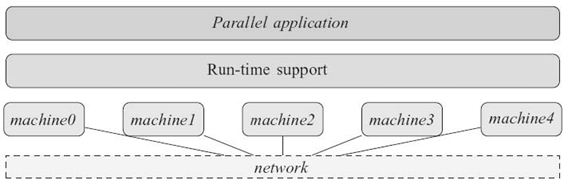
FIGURE 26.1. Run-time support for executing a parallel application on several machines: the run-time support provides services to the parallel application to help it use distributed resources.
26.2.1.2 Runtime Environment The runtime environment focuses on allowing the execution of the application. In the context of parallel applications, it must provide the following services:
- start-up, launching, and finalization of the parallel application as a whole while considering each process individually
- putting the processes in relationship with each other so that they are able to communicate with each other
- monitoring: failure detection, behavior to be followed upon process failures. Monitoring can be extended to a finer-grain watch on the state of the machines, such as supervision of data on the hardware state of the machines like CPU load or temperature. The runtime environment then chooses whether or not to start processes on a given machine or to migrate them on a healthier machine at runtime.
The runtime environment is generally composed of a set of (daemon) processes executed on the machines that are used by the application. Each process of the application is managed by a daemon of the runtime, with which it can communicate. In general, the daemon is executed on the same compute node as the process(es) it is managing. Some supercomputers such as BlueGene/L are exceptions, since BlueGene/L supports only one process, and the notion of “compute node” on this machine cannot be defined as “an instance of the operating system.” The runtime environment can be executed in a persistent fashion and used by several parallel applications or dedicated to a single application.
These daemons are interconnected together, forming a connected topology. This topology is used for communications within the runtime environment. Hence, it forms a communication infrastructure, used by the daemons of the runtime environment to communicate and circulate messages. These messages are called out-of-band (OOB) messages because they are strictly internal to the runtime environment and are not used by the parallel application itself.
The software stack executed on each machine involved in a parallel computation is depicted in Figure 26.2. The runtime environment provides services to the parallel application and to the communication library.
26.2.2 Portability
The runtime system also provides hardware portability. If we keep the example of interprocess communications, the networks available for communications can be different between executions if the machines used are not the same. For instance, the application can be executed on a cluster that features a high-speed network that requires specific libraries to be used and then on another cluster that uses only an Ethernet network. The interconnection network technology is hidden from the application by the abstraction provided by communication primitives provided by the runtime system.
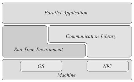
FIGURE 26.2. Software stack running on a machine that is part of the execution of a parallel application. The run-time support (made of the run- time environment and the communication library) is placed between the hardware and the application.
Hence, the runtime system provides an abstraction layer that provides the application with high-level communication routines and hides the communication media by taking care of low-level management. The application can focus on communications themselves rather than on how they are performed.
26.2.3 Support Provided to the Application and Communication Library
The runtime environment is meant to support the life cycle of the parallel application and to support it during its execution.
It supports the life cycle of the application by deploying it on the available resources. During the execution, it monitors the state of the application and it takes the appropriate actions upon failures. At the end of the execution, it makes sure the parallel application is terminated.
During the execution, it is in charge of forwarding I/Os and signals from and to the processes of the parallel application. It also supports the communication library by permitting interprocess communications.
26.3 COMMUNICATION INFRASTRUCTURE
The daemons of the runtime environment are interconnected by a given topology. This set of links forms a communication infrastructure used by the runtime environment to transmit OOB messages, that is, messages used internally (information circulation, I/O and signal forwarding, transmission of commands). The performance of this communication infrastructure is crucial for the scalability of the runtime environment and the features provided to the application.
This section takes a closer look at the communications that are transmitted within the runtime environment in Section 26.3.1. The performance criteria that are taken into account for scalability are examined in Section 26.3.2. Finally, in Section 26.3.3, we propose a scalable communication infrastructure for runtime environments.
26.3.1 Communications within the Runtime Environment
The runtime environment is meant to support the execution of parallel application. The first aspect of this support is to provide features for the life cycle of the application.
26.3.1.1 Application Start-Up At first, the application must be started on each one of the compute nodes that are available for it. A list of nodes is provided to the runtime environment by the job scheduler. Starting an application consists in launching remotely a command on each of these nodes. This command can be different for each process, as required, for example, by the MPI specification [3]. The command to be started on each node circulates on the communication infrastructure of the runtime environment.
26.3.1.2 Connecting Processes with Each Other During the course of the application's execution, the runtime environment must provide an information service on the contact information of the processes. If a process needs to communicate with another process, it will need to find out how the remote process can be contacted. This information is provided through circulation of the contact information of the processes of the application.
The runtime environment collects this information from each process during the initialization phase of the communication library. There exist two approaches to return this information to the processes.
The first approach can be called the prefetching approach. At the end of the initialization phase of the library, each process of the application has in its memory all the contact information of all the other processes. At runtime, when it needs to communicate with another process, it just has to look in its local memory and find this information. A variant of this approach consists in keeping all the contact information in the local daemon's memory. An application process that needs the contact information of another process asks its local daemon, which is a local, inexpensive communication.
In this approach, the information is fully replicated in all the compute nodes used by the application. This can be considered at first glance as expensive in terms of memory consumption. However, if we are considering TCP/IPv4 networks, the contact information for one network interface card (NIC) is made of 4 + 1 bytes. If each process uses two NICs, the contact information for each process uses 10 bytes. For an execution involving 220 processes (about a million), the total size for this information is 10 MB, which is totally reasonable considering the available memory on current machines.
The second drawback of this approach is the fact that it requires a synchronization between all the processes of the application. This circulation of information is actually a collective operation. All the processes put together their contact information and the result of this operation is distributed among all the processes (allgather operation, in MPI terminology).
This approach is the most common approach for current implementations of the MPI standard, such as Open MPI and MPICH2. The two aforementioned drawbacks have been so far considered as reasonable.
The second approach can be called the on-demand approach. The application processes declare their contact information to the runtime environment at startup time, just like in the prefetching approach. The difference is on how this information is distributed to the application processes. Unlike the previous approach, the information is not distributed among the approach processes at the beginning of the execution but only when a process needs it.
During the initialization phase of the library, the runtime environment only gathers the contact information of all the processes. At runtime, when a process needs to communicate with another process, it has to query it from the runtime environment. If the information is not available in the local daemon's memory, the query circulates within the runtime environment until this information is found and transmitted to the process that needs it.
This approach leverages a more lightweight initialization of the application since it does not require any synchronization between the processes. Whether or not paying the cost of this synchronization is a reasonable option will probably be crucial for very-large-scale systems.
Moreover, it can be useful on systems that have dynamic properties. For example, the MPI implementation targeting institutional grids QCG-OMPI [11] provides features such as NAT and firewall bypassing. Depending on the configuration of the administrative domains of the sites used by the computation, these features can rely on dynamic properties such as changing ports or use advanced connectivity techniques to establish interprocess communications. Hence, QCG-OMPI provides the contact information of remote processes when they are required.
The second purpose of communications within the runtime environment is I/O and signal forwarding. This service is provided by the runtime environment. For example, if the user wants to send a signal to each process of the parallel application, this signal must be transmitted by the runtime environment to each one of the processes of the application. In a similar manner, if a process of the parallel application performs an output on its standard output, stdout, it must be forwarded to the user's stdout (in general, the standard output of the process that initiated the parallel application, such as mpiexec in the context of MPI applications).
26.3.1.3 Forwarding I/O s and Signals The runtime environment forwards these signals and I/Os through its communication infrastructure. Hence, it can be used as a concentration network (many-to-one communication) and as a distribution network (one-to-many communication).
To summarize, the communication infrastructure of a runtime environment for parallel application must support the following communications:
- Collective Communications. One-to-many and many-to-one communications, data gathering, data gathering with or without redistribution of the result, synchronization barrier.
- Point-to-Point Communications. One-to-one communication between two daemons of the runtime environment.
26.3.2 Performance Criteria for Scalability
The topology of the communication infrastructure must allow it to scale and to communicate in a scalable way. From a performance point of view, two criteria on this topology must be examined carefully to determine whether a topology is scalable or not.
The first one is the diameter of the graph formed by this topology. The diameter is the longest distance between two nodes of a graph. In other words, if a process sends a message to another process, the diameter is the maximal number of hops that this message will have to do to reach its destination.
If the diameter of the graph of the topology used by a runtime environment is large, it will perform poorly on both point-to-point and collective communications since the latency of the communications will be high.
The second criteria is the degree of the vertices of this graph. The degree of a vertex of a graph is the number of edges that are connected to this vertex. In the context of runtime environment, it is represented by the number of daemons that are connected to a given daemon.
If the degree of a node of the communication infrastructure is high, the daemon will have to manage a large number of other daemons. In terms of system implementation, it means that the daemon will have to poll over a large number of sockets. At a lower level, the network buffers will have to handle a large number of communications and, in case of a connection storm or of an intense concentration of incoming communications (many-to-one communication), some of these buffers may be overflown and some packets may be lost.
Hence, a scalable topology for the communication infrastructure of a runtime environment must have a good trade-off between these two criteria.
26.3.3 Scalable Communication Infrastructure
A star topology (all the daemons are connected to a master daemon, also called seed) is the most basic topology there is. It has a diameter of 2: A message can reach any daemon in two hops, except if the sender or the receiver is the master daemon, in which case it is sent directly to the receiver. However, if N denotes the total number of daemons, the master daemon has a degree that is equal to (N − 1). The seed daemon has to manage connections from all the other daemons and to forward all the messages sent between them, which makes it a central point of congestion. Hence, and for the reasons listed above, this topology is not suitable for large-scale systems.
An opposite topology would be an undirected ring topology. Each node is connected with two other nodes, considered as its neighbors. The degree of each node is equal to 2. The diameter, however, is too large to be reasonable since it is equal to ⌈N/2⌉. Each daemon has to manage only two other daemons, and there is no central point in this topology. However, message latency is too high and grow linearly with the number of daemons. This topology is therefore not suitable for large-scale systems either.
Tree-based topologies are often used for collective communications because they allow a good parallelism between the communications. Fibonacci trees (also called k-ary trees) and binomial trees are among the trees that are commonly used for one-to-many and many-to-one communications. On a one-port model, that is, a model in which a process can only send or receive one message from or to one other process, the binomial tree algorithm has been proven to be optimal in number of messages for a power-of-two number of processes and quasi-optimal if the number of processes is not a power of two.
In most cases, messages are sent on the communication infrastructure of a runtime environment from or to the seed daemon, and the one-to-many and many-to-one communications are rooted by the seed daemon. Hence, regarding this property of the communication patterns, a tree topology is a reasonable choice for the topology of a communication infrastructure. The degree of all the nodes (except the leaves) of a Fibonacci tree is the parameter k of the tree. In a binomial tree, it is at most log2(N). The depth of a Fibonacci tree is logk(N), and that of a binomial tree is log2(N). Hence, if messages can be rooted up and down the tree, the diameter of a binomial tree is ![]() (log2(N)) and the diameter of a Fibonacci tree is
(log2(N)) and the diameter of a Fibonacci tree is ![]() (logk(N)).
(logk(N)).
This seed-based tree topology sets a central role for the seed daemon. If we consider a topology where each daemon is the root of a binomial tree, we obtain a topology where a message can be sent by any daemon and reach any other daemon in, at most, log(N) hops without any routing up and down the tree while maintaining a degree in ![]() (log2 (N)). This topology is called a binomial graph [12].
(log2 (N)). This topology is called a binomial graph [12].
Like tree-based topologies, binomial graphs have good properties for one-to-many and many-to-one collective operations. They are also well suited for data gathering with redistribution of the result (allgather in the MPI terminology) since specific algorithms can take direct advantage of the topology [13]. Tree-based topologies, on the other hand, have to perform this operation in two steps: They first gather the data and then broadcast the result.
For these reasons, binomial graph topologies present good properties for large-scale systems. They take tree-based topologies'good communication performance abilities and add more flexibility while keeping a logarithmic degree. Besides, we will see other properties of binomial graphs in Section 26.5.
26.4 APPLICATION DEPLOYMENT
In this section, we present the first role of a runtime environment: how it starts a parallel application on a set of available computing resources. First, we present how an application is deployed in Section 26.4.1. Then we explain why the deployment topology is of major importance at a large scale in Section 26.4.2. Last, we present an approach for scalable application deployment in Section 26.4.3.
26.4.1 Steps in the Deployment of an Application
A parallel application is deployed by the runtime environment on a set of remote resources provided by the job scheduler. At first, the runtime environment must be deployed on these resources. Then it proceeds with launching the processes of the parallel application on the computing nodes.
When a daemon is started, it must join the communication infrastructure. Most of the time, this infrastructure uses a TCP network. It does not use the high-speed network, if any is available, in order to keep it free for the communications of the parallel application. Hence, each daemon of the runtime environment starts with the contact information (IP address and port) of another daemon, which is waiting for incoming connections as a parameter.
As a consequence, before starting other daemons, the very first step of the deployment process consists in opening a socket and starting to listen on it. How the port this socket is listening on is chosen can be discussed. It can be a fixed port, in which case the port is already known by all the daemons of the runtime environment. However, this is a limitation for the system since the chosen port may not be free on all the resources. A direct consequence is that two instances of the runtime environment cannot run on the same machine (in the case, e.g., of a multicore machine that is shared by several applications).
If the port is not fixed and known in advance, it has to be discovered when the socket is opened and transmitted to the daemons that are further started. For portability reasons, the IP address of the machine that runs the daemon that will accept incoming connections cannot be known in advance and must also be provided when a daemon is started.
Once the runtime environment is running on the computing nodes, the parallel application can be started. The command to launch on each node is communicated to the daemons of the runtime environment by a communication on its communication infrastructure and, upon reception of this command, daemons spawn their local processes.
The last step is related to the support of the communication library. At the beginning of the execution of the parallel application, the communication library must be initialized. At this moment, it discovers the available communication interfaces it can use to communicate and declares it and how it can be contacted on these interfaces (its contact information) to the runtime environment. This information is kept in the runtime environment, as discussed in Section 26.3.1.
Therefore, the command that starts a parallel application proceeds as follows:
- Get the list of resources to be used for the computation.
- Open a socket; discover which port it is listening on.
- Spawn daemons on remote resources.
- Build the communication infrastructure.
- Broadcast the command to be launched on the remote resources.
- Initialize the communication library.
The daemons of the runtime environment can simply join the communication infrastructure by connecting to the daemon whose contact information has been passed to it as a parameter (the communication infrastructure's point of contact), but it can also be part of it as an active node of the infrastructure and can accept incoming connections. Various topologies for the communication infrastructure are presented in Section 26.3.3.
Each daemon of the runtime environment takes part in the application start-up as follows:
- Start on a given compute node.
- Connect to the communication infrastructure's point of contact.
- If the daemon has to be connected to by other daemons, open a socket and then discover which port it is listening on.
- If the daemon has children in the deployment process, spawn child daemons.
- Receive the command corresponding to the parallel application.
- Spawn the local processes of the parallel application.
- Initialize the communication library.
26.4.2 Importance of the Deployment Topology
Deploying a runtime environment consists in spawning a daemon on remote resources. Hence, a fast deployment relies on a fast spawning algorithm, that is, an algorithm that can propagate commands in the smallest possible number of steps.
The most naive deployment topology is a star. The initial daemon is called seed. 1 The seed daemon spawns all the other daemons one by one. In a one-port model, where a daemon can spawn one daemon at a time, such a deployment on N daemons (plus the seed daemon) takes N steps.
Inspired by one-to-all broadcast algorithms, a k-ary tree allows several remote spawns to be performed in parallel. The height of a k-ary tree containing N nodes is equal to logkN. Each node spawns at most k remote daemons that will, if they are not leaves of the tree, spawn at most other k daemons. Hence, in a one-port model, the total time required to spawn N daemons is equal to N logkN.
A binomial tree topology extracts a high parallelism between spawns. In a one-port model, it is the optimal deployment topology if the number of daemons that must be spawned is a power of two, and quasi-optimal if the number of daemons is not a power of two. Each daemon of rank r spawns the daemons of ranks rk = r + 2k, k being integers strictly larger than ⌊log2r⌋ and such that rk is smaller than N (i.e., ⌊log2r⌋ < k ≤ ⌊log2(N‒r)⌋). In a one-port model, the total time required to spawn N daemons using a binomial tree is equal to ⌈log2N⌉.
As a consequence, the deployment time depends strongly on the topology used to deploy the runtime environment. At a large scale, the binomial tree requires the smaller number of steps among the three topologies presented here. The three topologies described above are depicted in Figure 26.3.
Figure 26.3a shows a star topology with six daemons in total. The seed daemon spawns five daemons.
Figure 26.3b shows a binary tree topology with seven daemons in total. Each daemon spawns two nodes, except the leave nodes. The daemon of rank 6 is spawned last. It is the second daemon spawned by its parent daemon, daemon 2. Daemon 2 is the second daemon spawned by the seed daemon. In total, the last daemon is spawned after four steps.
Figure 26.3c shows a binomial tree topology with eight daemons in total. During the first time step, the seed daemon (called daemon 0) spawns daemon 1. During the second time step, daemon 0 and daemon 1 spawn one daemon each: daemon 2 and daemon 3. During the third time step, the four daemons spawn one daemon each. Hence, spawning these seven daemons using a binomial tree requires three time steps (see Fig. 26.4).
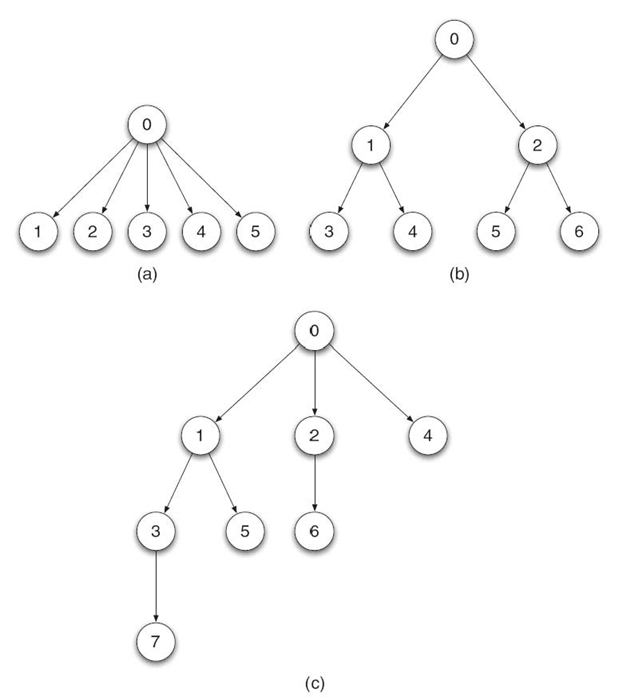
FIGURE 26.3. Some possible deployment topologies: (a) star, (b) binary tree, and (c) binomial tree.
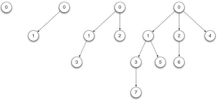
FIGURE 26.4. Steps in a binomial tree-based deployment.
26.4.3 Scalable Application Deployment
If the communication infrastructure (described in Section 26.3) is built independently from the deployment of the runtime environment and in a centralized manner, all the daemons join the communication infrastructure by connecting to the daemon they know, that is, the seed daemon. This can cause a connection storm on the seed daemon.
One can notice that tree-based topologies are suitable for both the deployment and the communication infrastructure 2 of the runtime environment. As a consequence, the construction of the communication infrastructure can be done in a distributed way, while the deployment progresses along the deployment tree.
Distributing the construction of the communication infrastructure eliminates the central point of congestion that exists on the seed daemon with centralized approaches. Moreover, the tree of the communication infrastructure is therefore built directly and does not require execution of any specific algorithm to construct the tree after the deployment.
We have seen in Section 26.4.1 that daemons join the communication infrastructure by connecting themselves to another daemon whose contact information is passed at spawn time. In the centralized approach, all the daemons are given the contact information of the seed daemon. A distributed approach consists in giving the contact information of several daemons instead of only one. As a consequence, the connections are distributed between several daemons.
In a tree-based deployment, each daemon can connect to its parent in the deployment tree. Therefore, the communication infrastructure is built along the deployment tree with a matching topology. The number of incoming connections that must be handled by each node is equal to its degree in the topology graph: There is no central point of congestion that needs to handle a connection storm, such as the one induced by a centralized approach.
The performance of these approaches has been compared and analyzed in Reference 15. We have measured the time required to deploy a trivial application (/bin/true) on the GdX cluster of the Grid'5000 testbed [16]. This cluster is made of 342 nodes that feature two AMD Opteron CPUs (two frequencies are available: 2.0 and 2.4 GHz), 2 GB of RAM, 2-Gb Ethernet NICs and a Myri10g NIC. The Myrinet switch features 512 ports. In order to have a flat network topology, we used the TCPoMX driver. These two approaches have been implemented in Open MPI version 1.4a1. Daemons were spawned on remote resources using the Secure Shell (SSH) client.
The deployment time of this trivial application is represented in Figure 26.5. We ran each experiment 10 times, and the values plotted on this figure are the mean and the standard deviation. We can see that at a small scale (less than about 40 nodes), the star topology performs better: It is more simple and, at this scale, congestion issues do not really matter.
The deployment time of the tree-based approach increases quasi-logarithmically, with a step when the number of nodes is a power of two.
On the other hand, the deployment time with a star-based topology increased almost linearly, with a 3-second step around 140 nodes and a high standard deviation around this number of nodes. We used the traffic monitoring tool tcpdum 3 to count the incoming TCP SYN packets on the machines on which we spawned remote daemons. We noticed that beyond about 140 nodes, some packets were sent twice. They had probably been lost because of an overflowing backlog buffer, which had a size of 128 on this machine. The number of nodes beyond which packets were lost changed a bit between executions, ranging from about 135 to 145, which explains the variations between measurements and, therefore, the high standard deviation. If a SYN packet is lost, the client machine does not receive any SYN/ACK packet. It retries to send this SYN packet after 3 seconds for the first time. As a consequence, the TCP connection itself takes at least 3 seconds. This can explain the 3-second delay in the star-based, centralized deployment.
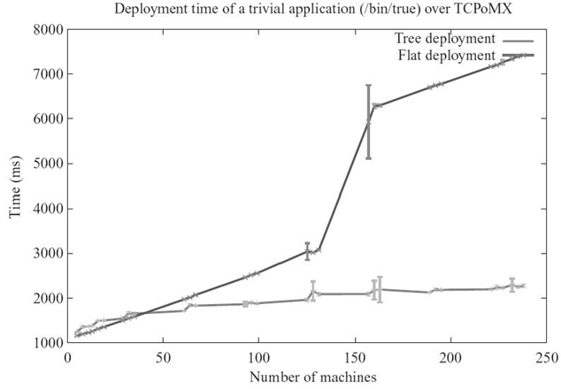
FIGURE 26.5. Deployment time of a trivial application using a tree-based topology and a star topology.
The distributed approach presented here presents promising results by constructing the communication infrastructure as the deployment of the daemons of the runtime environment progresses, and, since it is distributed, it eliminates central points of convergence.
However, it requires a tight integration of the communication infrastructure with the spawning system. A custom, integrated launching system with SSH was used in the implementation presented here, which allowed us to interleave the launching system with the construction of the communication infrastructure. This cannot be achieved if a third-party launching system is used, such as, for instance, OAR [17], SLURM [18], or Platform LSF. 4 In this case, all the daemons are spawned with similar command-line arguments and environment variables: They all get the same contact information. Moreover, the distributed approach requires that each daemon opens a socket in listen mode and then proceeds with its participation to the spawning tree. Third-party launching systems spawn all the daemons at once and do not allow interleaving of the deployment itself and local actions on the daemons.
26.5 FAULT TOLERANCE AND ROBUSTNESS
In this section, we describe the role of the runtime environment when failures occur. Failures are inherent to large-scale systems and cannot be ignored for large-scale applications [19]. The runtime environment has a major role to play in the robustness and fault tolerance of the application.
The most basic task it must fulfill for fault tolerance is failure detection. We describe in Section 26.5.1 how this can be achieved.
To be able to support robust parallel applications, the runtime environment must be robust itself. Section 26.5.2 describes some possible topologies for the communication infrastructure and examines their properties in terms of robustness.
Last, in Section 26.5.3, we describe how this support for fault tolerance can be carried out, in function of what is expected from the runtime environment. We see that the features that must be provided by the runtime environment depend on the type of fault-tolerance mechanisms that are implemented and which features are required by different categories of fault-tolerance mechanisms.
26.5.1 Error Detection
Monitoring the state of the processes of the parallel application is part of the role of the runtime environment. The most basic monitoring service consists in detecting failures. When a machine on which processes of the parallel application are running fails, the runtime environment must detect it and take appropriate actions.
The most common failure model is the fail-stop model [20]: Upon failures, the processes stop doing anything. Such failures are considered definitive: A failed process will not work again later with no intervention.
Besides, it is often considered that machines fail as a whole: If a failure occurs on a machine, all the processes running on this machine are crashed. In general, a daemon of the runtime environment is running on each machine involved in a parallel application. Hence, if the runtime environment detects that one of its daemons is dead, it considers that the processes running on this machine are dead as well.
Failure detection is not a trivial problem. If a daemon stops answering requests, is it dead or is it just slow? This problem is equivalent to a distributed system problem called group membership service (GMS). The set of daemons of the runtime forms a group, and when a daemon dies, it is considered as leaving the group. Yet, it has been proven to be impossible for asynchronous systems with failures in Reference 21.
Heartbeat [22] is a failure detector that is unreliable and eventually perfect. It is unreliable because at a given moment, daemons or processes are suspected to be dead, but for the aforementioned reasons, the failure detector cannot say if it is dead or not. It is eventually perfect because if a daemon dies, it is eventually detected as dead and, conversely, if a daemon is alive, there is a time after which it is not suspected to have crashed.
Each daemon of the runtime environment maintains a list of other daemons it is watching. Daemons periodically send messages to their neighbors: These messages are called heartbeats. Each daemon maintains a vector of counters corresponding to the heartbeats it has received from the other daemons. If it suspects the failure of a daemon, it puts it into a local list of suspected daemons. Some processes may be wrongfully put in this list, for example, if their heartbeat has been received late. If the heartbeat is received later, it is considered as alive and removed from this list.
Heartbeat circulates on the communication infrastructure of the runtime environment: Heartbeats are a specific kind of point-to-point OOB messages.
26.5.2 Robust Topologies
A runtime environment for parallel applications must be robust. The minimal criteria for this robustness is that the topology must remain connected upon failures. For example, the MPI standard versions 1.X, 2.0, and 2.1 specify that if a process of the parallel application fails, the whole application must be finalized. Hence, the surviving processes of the application must be terminated by a specific message that circulates on the communication infrastructure of the runtime environment.
The second level of robustness is when the runtime environment is able to heal itself. It can be done in two ways: Either the topology is reknit and the communication infrastructure keeps the same topology (but the number of daemons may or may not be different), or it is healed but the topology is degraded; that is, its properties and its structure are different from what they were before the failure.
A star topology is, in that sense, very robust. All the daemons are connected to only one central daemon. Under the assumption that the central daemon does not fail, it cannot be disconnected. However, we have seen in Section 26.3.3 that this topology is not scalable.
A ring topology is robust if no more than two nonconsecutive daemons fail at the same time. If only one daemon fails, the topology is not disconnected and its two neighbors can connect with each other to reknit the ring. It is used in multipur-pose daemon (MPD) [1]. More details about MPD are given in Section 26.6.1. However, and like the star topology, we have seen in Section 26.3.3 that the ring topology is not scalable.
Tree topologies have, as seen in Section 26.3.3, good scalability properties. However, they are not robust: If a node fails, all the processes in its subtree are disconnected from the rest of the system. Fibonacci trees (k-ary trees) can be modified by adding a ring that interconnects together the nodes placed at the same level of the tree. This topology is called a k-ary sibling tree [23]. They have the same advantages and the same drawbacks as regular trees in terms of performance. They are robust, except in some situations described in Reference 23. They were designed mostly to be able to keep working in spite of failures, without replacing the failed nodes.
Binomial graphs [24], described in Section 26.3.3, also have good scalability properties. They also have good robustness properties, as shown in Reference 12. If N denotes the number of nodes in the system, they can tolerate the failure of
![]() (log2(N)) nodes and
(log2(N)) nodes and ![]() (log2(N)) communication links. Hence, they can keep working in spite of failures, but they can also rebuild their topology, as seen in Reference 14.
(log2(N)) communication links. Hence, they can keep working in spite of failures, but they can also rebuild their topology, as seen in Reference 14.
26.5.3 The Runtime Environment as a Support for Fault Tolerance
Fault tolerance for parallel applications can be achieved in two ways: Either the application can tolerate failures itself or the execution support provides a fault-tolerance layer that makes failures transparent from the application's point of view.
In general, the runtime environment must be robust and able to heal itself upon failures. It must be robust in a sense that it must be able to keep serving the other nodes while recovering the failed processes. Depending on the fault-tolerance approach that is followed, it must also provide additional features to support the fault-tolerance mechanism.
Automatic fault tolerance does not require any modification in the parallel application. The runtime system (the runtime environment and the communication library) are in charge of tolerating failures from the underlying system. It often relies on rollback recovery: Processes are checkpointed by the runtime system on a regular basis and checkpoints are stored by a specific component of the runtime environment called a checkpoint server. Upon failures, failed processes can be restarted from their latest checkpoint on a new machine.
A large number of protocols for automatic, transparent fault tolerance exist. They can be coordinated (such as the well-known Chandy and Lamport algorithm [25], implemented in MPICH-Vcl [26] and MPICH- Pcl [27]) or uncoordinated, using message logging (sender-based message logging [28], causal message logging [29]) or deterministic properties of the application's communications [30]. Message-logging protocols require an additional component from the runtime environment to store causality information on the messages in order to be able to replay them in the same order if a re-execution is required: This component is called a message logger. Some protocols log the messages in channel memories [31], which are also provided by the runtime environment.
In the particular case of coordinated checkpoint‒restart protocols, upon failures, the whole application is restarted from a previous checkpoint. In this case, the runtime environment needs to terminate the application and restart it from a checkpoint. For other protocols, it must not only recover the failed processes (and in some cases help the communication library to replay logged messages) but must also keep serving the rest of the application that has not been hit by the failure.
Algorithm-based fault tolerance (ABFT) [32] requires the parallel application to handle fault tolerance itself. The application is responsible for recovering the state of the application and the data lost with the failed process. It also requires that the runtime environment provides features for the application to implement such mechanisms.
The fault-tolerant linear algebra (FTLA) package [33] implements this approach for linear algebra computations. It relies on a specific MPI middleware called fault-tolerant message-passing interface (FT-MPI) [34] that provides such features to the application. The programmer of the parallel application can choose the general behavior of the application upon failures between four possibilities: shrink, where the failed process is replaced and the naming of the surviving processes is modified so that the names form a continuous set of numbers; blank, where the failed processes are not replaced and the naming of the surviving processes is not modified; rebuild, where new processes are spawned to replace the failed processes and are given the same names as the failed ones; abort, where the application is terminated.
FT-MPI relies for these features on its runtime environment, HARNESS [35]. HARNESS uses a k-ary sibling tree, as described in Section 26.5.2, which allows it to maintain a connected communication infrastructure and, indeed, be able to serve the surviving processes while implementing the behavior specified by the programmer of the parallel application. It also provides some additional information to the processes of the parallel application so that they know if they are running for the first time or if they have been restarted.
The time taken by this healing protocol has been evaluated in Reference 15. Using the same platform as the one used in Section 26.4.3, we have injected failures on a parallel system and have measured the time spent between the failure injection and the end of the recovery protocol (i.e., the end of the initialization of the new MPI processes). For the sake of simplicity and symmetry, we have used a star topology: All the daemons are connected to a central daemon, as described in Section 26.5.2. We implemented a self-healing protocol in ORTE, which is Open MPI's runtime environment. We used intermediate time measurements to evaluate the time taken by each step of the recovery protocol:
- Failure Detection. When the failure of the remote daemon has been detected by the runtime environment.
- Before SSH. When the system has decided what actions must be taken and it is ready to launch a new daemon.
- Begin ORTE's Initialization. When the new remote daemon has been spawned and it is about to start its initialization.
- End ORTE's Initialization. When the remote daemon is done with its initialization and it is about to spawn the local processes of the application.
- Application Restart. When the new application processes are done with their reinitialization.
Figure 26.6a shows the scalability of the healing of the communication infrastructure and restart of processes located on the first machine of the system, with respect to the size of the overall system. Figure 26.6b shows the time taken by the healing protocol on a fixed-size system (250 machines), with respect to the rank of the killed daemon.
The time spent before the system starts spawning the new daemon looks constant. Actually, it involves going through lists of machines and local operations. These operations are computing operations, which take a negligible time compared to the time taken by operations over the network (operations involving communications). We can see that the time taken by the initialization of the new daemon of the runtime environment is constant when the first machine is killed, but it increases linearly with the rank of the killed machine. This is due to the linearity of the topology of the communication infrastructure of the runtime environment. When the communication infrastructure heals itself and integrates the daemon that has just been restarted, communications are involved within the runtime system. These communications are therefore performed in linear time.

FIGURE 26.6. Scalability of the healing protocol. (a) First machine killed. (b) Fixed size (250 machines), varying the rank of the killed machine.
The reinitialization of the application processes involve a pseudoglobal communication: The new process declares its contact information to all the other processes, and it receives all the other processes'contact information. Since there exists at least one process that knows the contact information of all the processes, the latter is done with only one communication. The former requires a global communication, which is executed in a time that increases with the size of the system.
We notice that even in the worst case (restarting the processes of the last machine of a large system), healing the runtime environment and restarting application processes is faster than restarting the whole application (see deployment performance measured in Section 26.4.3).
26.6 CASE STUDIES
This section presents two runtime environments used by popular open-source MPI implementations: MPD, used by MPICH2, and ORTE, used by Open MPI. These two runtime environments were designed following two different approaches, and we think they both should be described here.
26.6.1 MPICH 2/ MPD
MPICH2 [36] is a well-known MPI implementation and successor of MPICH [37]. The first runtime environment used by MPICH2 was the MPD [1]. It now also features a new runtime environment called Hydra. We are focusing here on MPD because of its interesting design and features.
MPD uses a set of daemons that are running on a set of machines and are interconnected together. They must be started before the MPI application and by a separate command (mpdboot). MPD does not finalize itself at the end of an MPI implementation: Indeed, it is not bound to the life cycle of a particular MPI implementation. It can be even used by several MPI applications at the same time.
MPD was originally meant to run persistently on a set of machines. The daemons can be started as the machines boot up, and potentially run forever. It was also designed in a matter of security since it was expected to be runnable with superuser privileges.
The MPD daemons are interconnected according to a ring topology. This topology is described in Section 26.3.3. It was chosen for several reasons. First, it is a very simple topology. Being connected with only two neighbors reduces the potential for connections from malicious programs. Moreover, it makes it easier to review by system administrators who want to audit the code of the daemons before they allow them to run with superuser privileges on the nodes.
Besides, one goal of the design of MPD was to avoid having any central manager or master component. Hence, and unlike treelike topologies, a ring topology fulfills this requirement.
A ring is also a robust topology. If a daemon dies, its neighbors detect the ring has been broken and connect themselves together in order to reknit the ring. If no simultaneous failures occur, the topology is not disconnected.
The properties in terms of scalability obtained by this choice are questionable and are worth a discussion. A ring is scalable in terms of numbers of connections: Each daemon has to handle only two connections. However, as described in Section 26.3.3, it is not scalable in terms of diameter and, therefore, in the number of hops in the communications.
The trade-off between the degree and the diameter of the communication infrastructure's topology, described in Section 26.3.2, was chosen regarding the machines that were commonly used and foreseen for future machines at the time when MPD was designed.
The structure of MPD and how it supports MPI applications is depicted in Figure 26.7. The MPD daemons are running on the machines of the cluster and are interconnected by a ring topology. When an MPI application is started on a given set of nodes, the application connects itself to the MPD ring and communicates the command. The MPD daemons on the nodes that will be used are cloned, and each of them starts a specific daemon called process manager (PM). The PMs of a particular MPI application are interconnected by a ring topology and control the MPI application. Hence, the set of PMs is an instance of the runtime environment dedicated to a given MPI application.
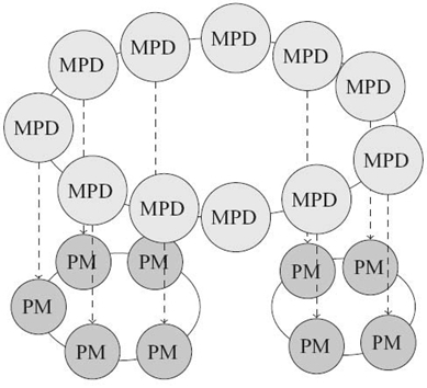
FIGURE 26.7. MPICH2's run-time environment MPD and two applications spawned over part of the available resources.
The PMs are forked to execute the application's processes on the nodes. The basic operations required to support the life cycle of a parallel application are defined by the process management interface (PMI [38]) and are implemented by MPD.
For example, if a process of the MPI application needs to connect to another process to perform a communication, it first asks its runtime environment how the remote process can be contacted. This operation is defined by the PMI and implemented by MPD to provide this information service to the parallel application.
26.6.2 Open MPI /Open RTE
Open MPI [39] is another well-known open-source MPI implementation. It relies on a modular architecture [40] that makes it flexible and portable. It is composed of three sections:
- a low-level layer that ensures portability (open portability abstraction layer)
- the runtime environment (open runtime environment)
- the implementation of the MPI application programming interface (API) (OMPI).
These three sections are not actually layers, but they interact with one another and with the local operating system as depicted in Figure 26.8.
Each internal functionality is provided by a framework that provides an API implemented in the components. A component implements a way to fulfill the functionality featured by the framework; for example, high-level communication routines can be implemented for different kinds of networks. Concretely, a component is implemented in a dynamic-linked library. With some frameworks, several instances of components (and even several instances of the same component) can be used at the same time, for example, if the system provides several kinds of networks and we want to be able to use them all. At runtime, one or several instances of a component that is linked by the system and used by Open MPI is called a module.
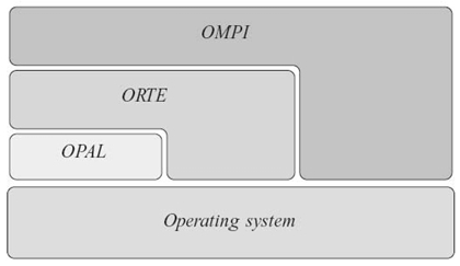
FIGURE 26.8. General view of the architecture of Open MPI.
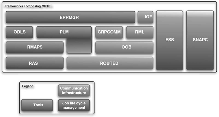
FIGURE 26.9. Architecture of ORTE: organization of the frameworks.
Each framework provides a given feature. However, they do not all depend on one another like in a layered architecture. For instance, there is no relationship between the framework that is in charge of spawning the remote daemons and the one in charge of OOB communications.
The organization of the frameworks of ORTE is depicted in Figure 26.9. They can be sorted into three categories:
- the frameworks that manage ORTE's and the application's life cycles, that is, deployment of the runtime environment, spawning of the application, and error management
- the frameworks that compose the communication infrastructure
- the tools that interfere with all the runtime environment itself.
Since we are focusing here on ORTE [41], we will describe the various frameworks it is composed of and see how the features described in this chapter are provided by it.
26.6.2.1 Job's Life Cycle
Resource Allocation System (RAS) The RAS is in charge of getting the resources the application will be executed on. It can read a file profided by the user of by a resource reservation system. The various components available allow support of several methods to obtain this resource list, depending on the reservation system that is used.
Resource Mapping System (RMAPS) The RMAPS is in charge of matching the processes of the MPI application, the daemons of the runtime environment, and the list of available machines obtained by the RAS. The various components available implement several policies to schedule the processes over the available resources such as, for instance, round-robin.
Process Life Cycle Management (PLM) The PLM is in charge of the deployment of the runtime environment according to the map determined by the RMAPS. It spawns daemons on remote machines and makes sure they join the communication infrastructure. Once the daemons are ready, it propagates the command that spawns the application processes from the daemons.
Open RTE Daemon's Local Launch Subsystem (ODLS) The ODLS is in charge of spawning the local application's processes that will be attached to the local daemon. For this purpose, it uses the map determined by the RMAPS and clones the daemon process to spawn the application's processes.
Error Manager (ERRMGR) The ERRMGR frameworks implements error detection mechanisms and the behavior that ORTE follows upon node failures. For instance, one component implements clean termination of the application and folding of the runtime environment if a daemon is detected as dead. Fault-tolerance policies can be implemented as components of this framework, such as spawning of a new daemon to replace the failed one (as described in Reference 15).
26.6.2.2 Communication Infrastructure
ROUTED The ROUTED framework computes the routing tables of the communication infrastructure. Messages are routed through a communication infrastructure by intermediate daemons that forward them toward their destination; the ROUTED framework computes these routes for each message sent and, more precisely, the identifiers of the daemons it will be sent to. The various components available implement several routing algorithms.
OOB Low-level communications are implemented by the OOB framework. In order to keep the communications of the application free of any disturbance if they are performed on a high-speed network, the only component implemented uses TCP communications.
Runtime Messaging Layer (RML) The high-level communication routines used by the runtime environment are implemented by the RML framework. The RML calls the OOB and follows the active-message model.
Group Communications (GRPCOMM) Collective communications are an essential part of the features required by a runtime environment. They are implemented in ORTE in the GRPCOMM framework, which calls the ROUTED framework to choose where messages are routed and therefore send fewer messages. This framework uses the RML for point-to-point communications.
Input/Output Forwarding Service (IOF) I/Os from the application's processes are forwarded to the mpiexec process, which acts like a gateway between the application and the user, by the IOF framework.
26.6.2.3 Tools
Environment-Specific Service (ESS) During the initialization phase of the daemons of the runtime environment and the MPI processes, the ESS is in charge of the initialization of the ORTE part depending on the role of the process.
Snapshot Coordination Interface (SNAPC) This framework is used only by the rollback-recovery fault-tolerance system. It is in charge of initiating a checkpoint wave and of copying and storing the checkpoints on the machine that executes the mpiexec process.
26.7 CONCLUSION
In this chapter, we have examined some of the challenges faced by parallel, distributed runtime environments on large-scale systems. We have listed the services provided by runtime environments to support parallel applications running on a set of distributed resources and how their large scale makes them highly critical for the performance of the application.
We have emphasized the importance of the topology used by the runtime environment for several of the services it provides. We have seen that using matching topologies or compatible topologies (a binomial tree can be extracted from a binomial graph) leverages good performance and reduces the effects of communication concentration (e.g., connection storms or all-to-one collective communication patterns).
Fault tolerance is a critical issue for large-scale systems. Hence, we have examined it as an additional feature that must be provided by runtime environments. We have seen how the runtime environment can support various types of fault tolerance and how it must be handled internally by the runtime environment.
Finally, we have analyzed carefully how the runtime environments of two well-known, open-source parallel programming environments (MPICH2 and Open MPI) are implemented, which design choices have been made, and what the consequences of these choices are.
REFERENCES
[1] R.M. Butler, W.D. Gropp, and E.L. Lusk, “A scalable process-management environment for parallel programs,” in Recent Advances in Parallel Virtual Machine and Message Passing Interface, 7th European PVM/MPI Users'Group Meeting (EuroPVM/MPI'02) (J. Dongarra, P. Kacsuk, and N. Podhorszki, eds.), Vol. 1908, pp. 168–175, Springer, 2000.
[2] G. Tel, Introduction to Distributed Algorithms. Cambridge University Press, 1994.
[3] Message Passing Interface Forum, “MPI: A message-passing interface standard.” Technical Report UT-CS-94-230, Department of Computer Science, University of Tennessee, April 1994, May 22 101 17: 44: 55 GMT.
[4] A. Geist, W.D. Gropp, S. Huss-Lederman, A. Lumsdaine, E.L. Lusk, W. Saphir, A. Skjellum, and M. Snir, “MPI-2: Extending the message-passing interface,” in 1st European Conference on Parallel and Distributed Computing (EuroPar'96), (L. Boug é, P. Fraigniaud, A. Mignotte, and Y. Robert, eds.), Vol. 1123 of Lecture Notes in Computer Science, pp. 128–135, Springer, 1996.
[5] L. Dagum and R. Menon, “OpenMP: An industry standard API for shared-memory programming,” IEEE Computational Science and Engineering, 5: 46–55, 1998.
[6] UPC Consortium, “UPC Language Specifications, v1.2.” Technical Report LBNL-59208, Lawrence Berkeley National, 2005.
[7] C.C. Coarfa, Y. Dotsenko, J. Mellor-Crummey, D. Chavarria-Miranda, F. Cantonnet, T. El-Ghazawi, A. Mohanti, and Y. Yao, An evaluation of global address space languages: Co-array Fortran and unified parallel, June 2005.
[8] P. Hilfinger, D. Bonachea, K. Datta, D. Gay, S. Graham, B. Liblit, G. Pike, J. Su, and K. Yelick, “Titanium language reference manual.” Technical Report UCB/CSD-2005-15, UC Berkeley, 2005.
[9] D. Bonachea and J. Duell, “Problems with using MPI 1.1 and 2.0 as compilation targets for parallel language implementations,” International Journal of High Performance Computing and Networking (IJHPCN), 1 (1/2/3): 91–99, 2004.
[10] R. Namyst, Contribution á la conception de supports exécutifs multithreads performants . Habilitation á diriger des recherches, Université Claude Bernard de Lyon, pour des travaux effectués á l'école normale supérieure de Lyon, DEC 2001.
[11] C. Coti, T. Herault, S. Peyronnet, A. Rezmerita, and F. Cappello, “Grid services for MPI,” in Proceedings of the 8th IEEE International Symposium on Cluster Computing and the Grid (CCGrid'08) (T. Priol et al., ed.), pp. 417–424, Lyon, France: ACM/IEEE, May 2008.
[12] T. Angskun, G. Bosilca, and J. Dongarra, “Binomial graph: A scalable and fault-tolerant logical network topology,” in Proceedings of the 5th International Symposium on Parallel and Distributed Processing and Applications (ISPA 2007) (I. Stojmenovic, R.K. Thulasiram, L. Tianruo Yang, W. Jia, M. Guo, and R. Fernandes de Mello, eds.), Vol.4742 of Lecture Notes in Computer Science, pp. 471–482, Springer, 2007.
[13] J. Bruck, C.-T. Ho, S. Kipnis, E. Upfal, and D. Weathersby, “Efficient algorithms for all-to-all communications in multiport message-passing systems,” IEEE Transactions on Parallel and Distributed Systems, 8(11): 1143–1156, 1997.
[14] G. Bosilca, C. Coti, T. Herault, P. Lemarinier, and J. Dongarra, “Constructing resiliant communication infrastructure for runtime environments,” Advances in Parallel Computing, 19: 441– 451, 2010. Available at http://dx.doi.org/10.1016/j.future.2007.02.002.
[15] C. Coti, “Environnements d'ex é cution pour applications parallèles communiquant par passage de messages pour les systèmes à grande échelle et les grilles calcul.” PhD Thesis, Universit é Paris Sud-XI, November 2009.
[16] F. Cappello, E. Caron, M. Dayde, F. Desprez, Y. Jegou, P. Vicat-Blanc Primet, E. Jeannot, S. Lanteri, J. Leduc, N. Melab, G. Mornet, B. Quetier, and O. Richard, “Grid'5000: A large scale and highly reconfigurable grid experimental testbed,” in Proceedings of the 6th IEEE/ACM International Workshop on Grid Computing CD (SC|05), pp. 99–106, Seattle, WA: IEEE/ACM, November 2005.
[17] N. Capit, G. Da Costa, Y. Georgiou, G. Huard, C. Martin, G. Mounié, P. Neyron, and O. Richard, “A batch scheduler with high level components,” in Proceedings of the 5th International Symposium on Cluster Computing and the Grid (CCGRID'05), pp. 776–783, Cardiff, UK: IEEE Computer Society, May 2005.
[18] M.A. Jette, A.B. Yoo, and M. Grondona, “SLURM: Simple linux utility for resource management,” in Proceedings of the 9th International Workshop on Job Scheduling Strategies for Parallel Processing (JSSPP'03) (D.G. Feitelson, L. Rudolph, and U. Schwiegelshohn, eds.), Vol.2862, pp. 44–60, Springer-Verlag, 2003.
[19] D.A. Reed, C. da Lu, and C.L. Mendes, “Reliability challenges in large systems,” Future Generation Computer Systems, 22(3): 293–302, 2006.
[20] R.D. Schlichting and F.B. Schneider, “Fail stop processors: An approach to designing fault-tolerant computing systems,” ACM Transactions on Computer Systems, 1: 222–238, 1983.
[21] T.D. Chandra, V. Hadzilacos, S. Toueg, and B. Charron-Bost, “Impossibility of group membership in asynchronous systems,” in Proceedings of the 15th ACM SIGACT-SIGOPS Symposium on Principles of Distributed Computing, pp. 322–330, May 1996.
[22] M.K. Aguilera, W. Chen, and S. Toueg, “Heartbeat: A timeout-free failure detector for quiescent reliable communication,” in Proceedings of the 11th Workshop on Distributed Algorithms (WDAG'97) (M. Mavronicolas and P. Tsigas, eds.), Vol.1320 of Lecture Notes in Computer Science, pp. 126–140, Springer, 1997.
[23] T. Angskun, G.E. Fagg, G. Bosilca, J. Pjesivac-Grbovic, and J. Dongarra, “Self-healing network for scalable fault-tolerant runtime environments,” Future Generation Computer Systems, 26(3): 479–485, 2010.
[24] T. Angskun, G. Bosilca, and J. Dongarra, “Self-healing in binomial graph networks,” in OTM Workshops (2) (R. Meersman, Z. Tari, and P. Herrero, eds.), Vol.4806 of Lecture Notes in Computer Science, pp. 1032–1041, Springer, 2007.
[25] K.M. Chandy and L. Lamport, “Distributed snapshots: Determining global states of distributed systems,” ACM Transactions on Computer Systems, 3(1): 63–75, 1985.
[26] P. Lemarinier, A. Bouteiller, T. Herault, G. Krawezik, and F. Cappello, “Improved message logging versus improved coordinated checkpointing for fault tolerant MPI,” in IEEE International Conference on Cluster Computing (Cluster 2004), IEEE CS Press, 2004.
[27] D. Buntinas, C. Coti, T. Herault, P. Lemarinier, L. Pilard, A. Rezmerita, E. Rodriguez, and F. Cappello, “Blocking versus non-blocking coordinated checkpointing for large-scale fault tolerant MPI,” Future Generation Computer Systems, 24(1): 73–84, 2008. Available at http://dx.doi.org/10.1016/j.future.2007.02.002.
[28] A. Bouteiller, F. Cappello, T. H érault, G. Krawezik, P. Lemarinier, and F. Magniette, “MPICH-V2: A fault tolerant MPI for volatile nodes based on pessimistic sender based message logging,” in High Performance Networking and Computing (SC2003), Phoenix, AZ, IEEE/ACM, November 2003.
[29] A. Bouteiller, B. Collin, T. Herault, P. Lemarinier, and F. Cappello, “Impact of event logger on causal message logging protocols for fault tolerant MPI,” in Proceedings of the 19th IEEE International Parallel and Distributed Processing Symposium (IPDPS'05), p.97, Washington, DC: IEEE Computer Society, 2005.
[30] A. Guermouche, T. Ropars, E. Brunet, M. Snir, and F. Cappello, Uncoordinated checkpointing without domino effect for send-deterministic message passing applications, May 2011.
[31] G. Bosilca, A. Bouteiller, F. Cappello, S. Djilali, G. Fédak, C. Germain, T. H érault, P. Lemarinier, O. Lodygensky, F. Magniette, V. Néri, and A. Selikhov, “MPICH-V: Toward a scalable fault tolerant MPI for volatile nodes,” in High Performance Networking and Computing (SC2002), Baltimore, MD: IEEE/ACM, November 2002.
[32] Z. Chen, G.E. Fagg, E. Gabriel, J. Langou, T. Angskun, G. Bosilca, and J. Dongarra, “Fault tolerant high performance computing by a coding approach,” in Proceedings of the ACM SIGPLAN Symposium on Principles and Practice of Parallel Programming, PPOPP 2005, June 15–17, 2005, Chicago, IL (K. Pingali, K.A. Yelick, and A.S. Grimshaw, eds.), pp. 213–223, ACM, 2005.
[33] G. Bosilca, R. Delmas, J. Dongarra, and J. Langou, “Algorithm-based fault tolerance applied to high performance computing,” Journal of Parallel and Distributed Computing, 69(4): 410–416, 2009.
[34] G.E. Fagg and J. Dongarra, FT-MPI: Fault tolerant MPI, supporting dynamic applications in a dynamic world, 2000.
[35] G.E. Fagg and J.J. Dongarra, “HARNESS fault tolerant MPI design, usage and performance issues,” Future Generation Computer Systems, 18(8): 1127–1142, 2002.
[36] W. Gropp, “Mpich2: A new start for mpi implementations,” in Recent Advances in Parallel Virtual Machine and Message Passing Interface (D. Kranzlmller, J. Volkert, P. Kacsuk, and J. Dongarra, eds.), Vol.2474 of Lecture Notes in Computer Science, pp. 37–42, Berlin/Heidelberg: Springer, 2002.
[37] W.D. Gropp and E.L. Lusk, “A high-performance MPI implementation on a shared-memory vector supercomputer,” Parallel Computing, 22(11): 1513–1526, 1997.
[38] P. Balaji, D. Buntinas, D. Goodell, W. Gropp, J. Krishna, E. Lusk, and R. Thakur, “PMI: A scalable parallel process-management interface for extreme-scale systems,” in Recent Advances in the Message Passing Interface (R. Keller, E. Gabriel, M. Resch, and J. Dongarra, eds), Vol. 6305 of Lecture Notes in Computer Science, pp. 31–41. Berlin/Heidelberg: Springer, 2010.
[39] E. Gabriel, G.E. Fagg, G. Bosilca, T. Angskun, J.J. Dongarra, J.M. Squyres, V. Sahay, P. Kambadur, B. Barrett, A. Lumsdaine, R.H. Castain, D.J. Daniel, R.L. Graham, and T.S. Woodall, “Open MPI: Goals, concept, and design of a next generation MPI implementation,” in Recent Advances in Parallel Virtual Machine and Message Passing Interface, 11th European PVM/MPI Users'Group Meeting (EuroPVM/MPI'04), pp. 97–104, Budapest, Hungary, September 2004.
[40] B. Barrett, J. Squyres, A. Lumsdaine, R. Graham, and G. Bosilca, “Analysis of the component architecture overhead in Open MPI,” in Recent Advances in Parallel Virtual Machine and Message Passing Interface (B. Di Martino, D. Kranzlm üller, and J. Dongarra, eds.), Vol. 3666 of Lecture Notes in Computer Science, pp. 175–182, Berlin/Heidelberg: Springer, 2005.
[41] R.H. Castain, T.S. Woodall, D.J. Daniel, J.M. Squyres, B. Barrett, and G.E. Fagg, “The open run-time environment (openRTE): A transparent multi-cluster environment for high-performance computing,” in Recent Advances in Parallel Virtual Machine and Message Passing Interface, 12th European PVM/MPI Users'Group Meeting (B. Di Martino, D. Kranzlmüller, and J. Dongarra, eds.), Vol.3666 of Lecture Notes in Computer Science, pp. 225–232, Sorrento, Italy: Springer, September 2005.
1In general, the seed daemon is the same for the deployment topology and the communication infrastructure (see Section 26.3.3).
2A binomial graph can be built from any tree, as shown in Reference 14.