
Chapter Six
Construction Sites
Chapter Outline
- Introduction
- Security
- Staging Areas
- Equipment
- Utilities
- Erosion Control
- Outro
Learning Objectives
After reading this chapter, you should be able to:
- Describe the security and staging needs of a construction site.
- Identify and describe the functions of various types of construction equipment.
- Describe various erosion control techniques.
Introduction
Many engineers not only design infrastructure components and systems, but also supervise construction of their designs. This chapter will describe some aspects of the construction of the infrastructure components presented in Chapters 3, 4, and 5. Successful and efficient construction requires significant planning efforts, which will be discussed in later chapters. Construction engineers are responsible for construction site layouts, equipment specification, scheduling, and erosion control.
Security
Securing a construction site is important for public safety and to protect contractor equipment from theft and vandalism. Fencing with locked gates is typically needed at a minimum. At remote sites without fencing, valuable tools are often hoisted and stored suspended from cranes in tool boxes. Surveillance cameras are also used. Checkpoints for vehicles entering the site are common.
Staging Areas
In general, the size of the staging area is proportional to the size of the project (Figure 6.1). In high-density urban areas, where available space is limited, off-site staging may be required. Most projects require submittal and approval of construction staging plans prior to starting work. These plans typically include details not only of the staging area, but also of access routes for deliveries and worker parking, security fencing, dumpster locations, traffic control, covered pedestrian walkways (Figure 6.2), etc.
Staging areas are designated portions of construction sites for fabrication and for receiving and storing materials and equipment needed for project construction.
Figure 6.1 A Staging Area at a Building Construction Site.
Source: M. Penn.
Figure 6.2 A Covered Walkway for Safety of Pedestrians During Construction Activities.
Source: M. Penn.
Equipment
A wide variety of equipment is used during construction depending on the site conditions and the nature of the project. Most types of equipment are available in a wide range of sizes. Construction engineers determine which size is appropriate based on capacity, access, and other factors. As a basic introduction, only a few common types of equipment are included in this section. Many undergraduate civil engineering programs have a course to provide more detailed information on construction equipment.
TRAILERS AND STORAGE CONTAINERS
Trailers are used at construction sites for equipment and material storage as well as for on-site offices (Figure 6.1 and Figure 6.3). Portable metal containers are also used (seen in foreground in Figure 6.1).
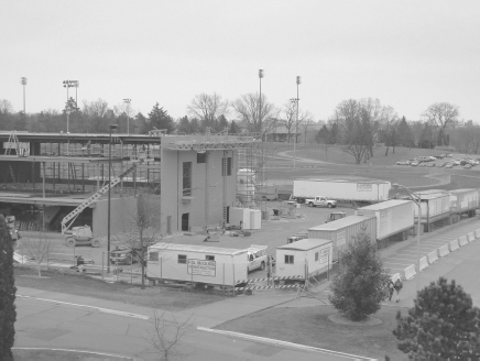
Figure 6.3 Trailers for Storage (Background) and Offices (Foreground, with Windows).
Source: M. Penn.
Figure 6.4 Cranes for High-Rise Building Construction (Background) in Oslo, Norway. The landmark Oslo Opera House is in the foreground.
Source: M. Penn.


CRANES
It has been said of city skylines that “where there are cranes, there is money.” Indeed large cranes are used for the construction of high-rise buildings (Figure 6.4). Many types of cranes are used; the type used depends on the height of the lift, weight of the objects, and access needs of a project (Figure 6.5, Figure 6.6, and Figure 6.7).
 Photos of Construction Equipment and Activities
EXCAVATORS
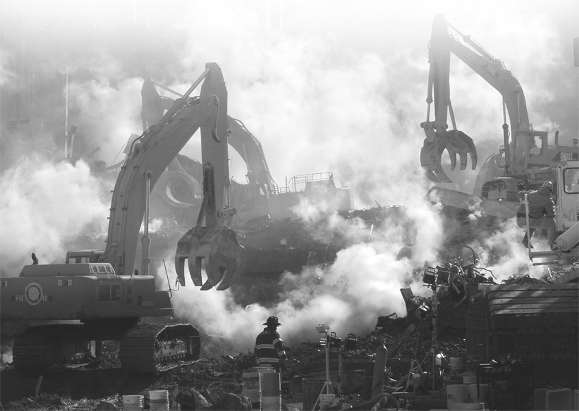
Excavators are used not only for general excavation, but also for trenching of utilities and placement of materials (Figure 6.8). Many attachments, such as grapples (Figure 6.9) and roller compactors, can replace the excavating buckets, making excavators one of the most very versatile types of heavy equipment. For smaller excavations, backhoes are commonly used (Figure 6.10).
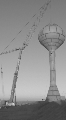
Figure 6.5 A Lattice Boom Crane Placing a Water Tower Tank on Its Pedestal.
Source: Courtesy of Laramie Equipment Co.
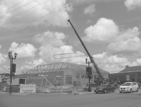
Figure 6.6 A Telescopic Hydraulic Crane Lifting a Truss into Position.
Source: M. Penn.

Figure 6.7 Tower Cranes Used for Skyscraper Construction.
Source: Copyright © Christopher Arndt/iStockphoto.
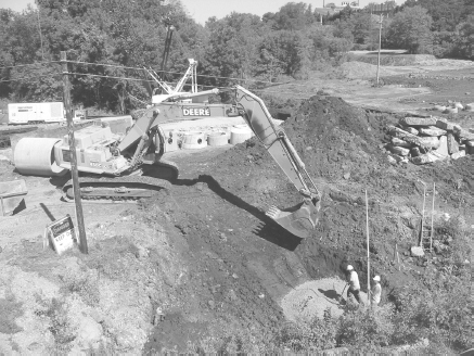
Figure 6.8 An Excavator Placing Crushed Stone at the Base of an Excavation.
Source: M. Penn.
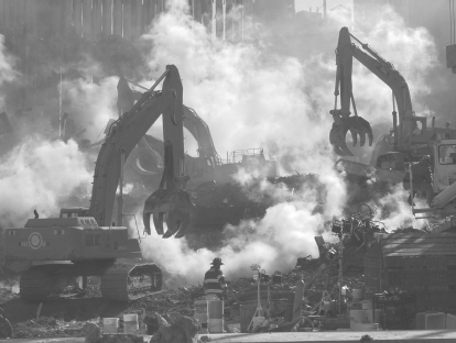
Figure 6.9 Excavators with Grapple Attachments Clear Debris at Ground Zero After the 9/11 Terrorist Attacks.
Source: Federal Emergency Management Agency/M. Rieger.
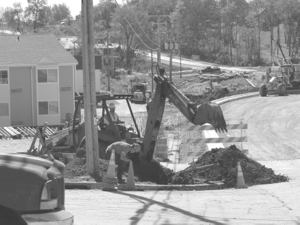
Figure 6.10 A Backhoe Utilized for a Small Excavation.
Source: M. Penn.
BULLDOZERS
Bulldozers (or dozers) are commonly used for rough grading of sites, including the placement of fill material (Figure 6.11).
![]() Remember that full-sized versions of textbook photos can be viewed in color at www.wiley.com/college/penn.
Remember that full-sized versions of textbook photos can be viewed in color at www.wiley.com/college/penn.
LOADERS
Loaders (Figure 6.12 and Figure 6.13) are used for a variety of purposes such as loading excavated material into trucks, placing of material, lifting equipment, etc.
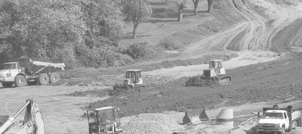
Figure 6.11 Two Bulldozers Leveling Soil at a Fill Site.
Source: M. Penn.
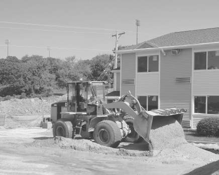
Figure 6.12 A Loader Placing Crushed Stone.
Source: M. Penn.
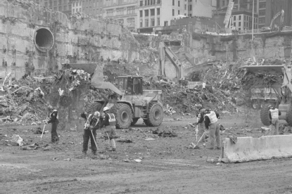
Figure 6.13 Front-End Loaders Placing Debris for Sorting at the World Trade Center Site After the 9/11 Terrorist Attacks.
Source: Federal Emergency Management Agency/L. Lerner.

Figure 6.14 Two Skidsteers Performing Different Functions—Street Sweeping (Foreground) and Placing Topsoil (Background).
Source: M. Penn.
SKIDSTEERS
Skidsteers, also termed skidloaders (Figure 6.14), are so named because of the wheels or tracks on one side are fixed during a turning maneuver. Turning is accomplished by braking one side of the vehicle while driving the other. Often generically referred to as “Bobcats” (a popular brand and one of the first four-wheeled skidsteers produced), skidsteers are built by many construction equipment manufacturers. A variety of implements have been designed to attach to the skidsteer (sweepers, jack hammers, etc.).
DUMP TRUCKS
Dump trucks are routinely used to remove excavated material or bring fill material to a site, as well as to haul away construction debris. There is a wide variety of truck designs to match site conditions and project needs (Figure 6.15 and Figure 6.16).
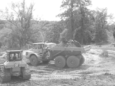
Figure 6.15 An Articulated Dump Truck for Use in Rough Terrain, with a Capacity of 40 Tons or 30 Cubic Yards.
Source: M. Penn.
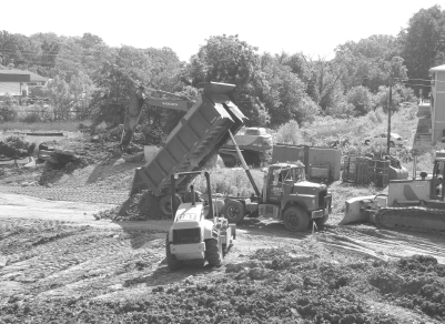
Figure 6.16 A Standard Dump Truck Placing Fill.
Source: M. Penn.
EARTHMOVERS
Scrapers (Figure 6.17) are used for rough grading and leveling sites. Unlike dozers that push soil, scrapers remove surface material into a hopper. Scrapers are analogous to planers used for woodworking. Graders (Figure 6.18) are used for final (smooth) grading.
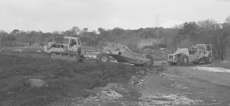
Figure 6.17 A Tow Scraper Pulled by a Tractor (Left), and a Self-Propelled Motor Scraper (Right).
Source: Courtesy of R. Schmitt.

Figure 6.18 A Grader Repairing a Road Damaged by Hurricane Rita.
Source: Federal Emergency Management Agency/M. Nauman.
LIFTS
Whereas cranes are used for high-elevation lifting, lifts (Figure 6.19) can be used for lower elevation lifting of material or as short duration working platforms. Scaffolding is used for elevated working platforms for longer duration (Figure 6.20).
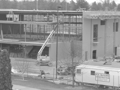
Figure 6.19 A Telescopic Lift Supporting Workers.
Source: M. Penn.
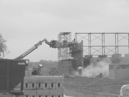
Figure 6.20 Three-Tier Scaffolding for Masonry Work.
Source: M. Penn.
BLASTING EQUIPMENT
Blasting with explosives is used for demolition as well as rock excavation (e.g., a road cut, whereby holes are drilled into the rock and filled with explosives; Figure 6.21, Figure 6.22, and Figure 6.23).

Figure 6.21 Two Drill Rigs Boring into Bedrock (Shallow Topsoil has Been Removed) for Blasting. The bent over worker (far left) is placing explosives into a bored hole.
Source: M. Penn.
Figure 6.22 The Site from Figure 6.21 After Blasting. Note the rock has been fragmented and has “heaved.” The rock will be excavated to lower the existing grade for a new roadway.
Source: M. Penn.
PILEDRIVERS
Piledrivers (Figure 6.24) are used to drive pilings for foundations either by raising and lowering a weight, hydraulic ram, or vibration.
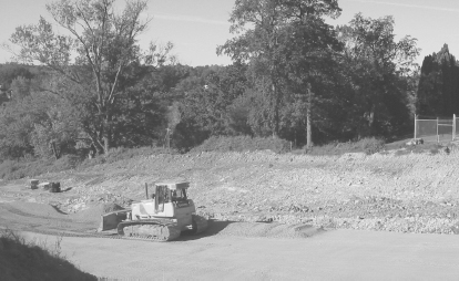
Figure 6.23 Final Road Grade Preparation After Completed Blasting and Excavation at the Site in Figure 6.21 and Figure 6.22.
Source: M. Penn.

Figure 6.24 The Piledriver (A), Attached to a Crane, Drives Steel Piles into the Subsurface. The piles (B) are lifted vertically into position and driven to the design depth, in this case approximately 50 feet. Once in the ground, the piles (C) are then cut at the surface (D) for integration into the building foundation.
Source: M. Penn.
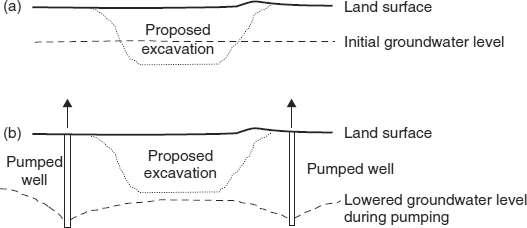
DEWATERING
Dewatering is not only required for underwater foundation construction, it is also necessary at sites where excavation depths exceed the depth to the local water table. In these situations, a series of shallow vertical groundwater wells are placed around the excavation, and pumped to temporarily lower the water table (Figure 6.25 and Figure 6.26). Failure to anticipate the need for dewatering can cause project delays and added construction expense. After large rain events, dewatering of excavations via portable pumps may be required. Proper grading of a site to minimize runoff into an excavation can minimize this need.
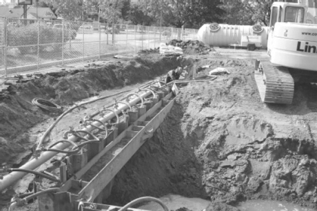
Figure 6.25 Preparing to Dewater an Excavation. Note that the excavation depth is below the water table. Hoses connected to the header pipe are connected to groundwater wells that will be pumped to lower the water table during construction.
Source: Courtesy of Peterson Geotechnical Construction, LLC.
Figure 6.26 Cross-Sections of an Excavation, (a) Before Dewatering and (b) During Dewatering. After construction work is complete, pumping will be halted and the water table will return to the original elevation.
READY-MIX CONCRETE TRUCKS
Perhaps the easiest way to be labeled as a “greenhorn” at a construction site is to refer to a ready-mix concrete truck (Figure 6.27) as a “cement mixer.” Cement is the bonding agent in concrete; concrete also includes aggregate (sand and gravel) and water. Ready-mix trucks deliver and place well-mixed concrete at construction sites.
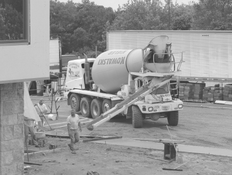
Figure 6.27 A Ready-Mix Concrete Truck Placing Concrete with a Chute for a Sidewalk.
Source: M. Penn.
CONCRETE PUMPING
When the concrete placement location cannot be reached by chute of a ready-mix truck because of access restrictions or elevation, a concrete-pumping truck may be used (Figure 6.28 and Figure 6.29).
Bridge Deck Pour Video
CONCRETE FORMS
Forms are moulds that are placed so that concrete can be poured into place for curing (Figure 6.30). After curing of the concrete is complete, temporary forms are removed. Formwork may be as simple as supported sheets of plywood, or may involve prefabricated modular units.

Figure 6.28 A Concrete Pumping Truck Places Concrete at the End of a Moveable Boom (the “M” Shape in the Photo). A ready-mix truck (right) supplies concrete to the pump.
Source: P. Parker.
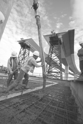
Figure 6.29 Concrete Being Placed Via Pumping. Note the reinforcing steel matrix through which the concrete is poured.
Source: Courtesy of Caltrans, District 4 Photography/J. Huseby.
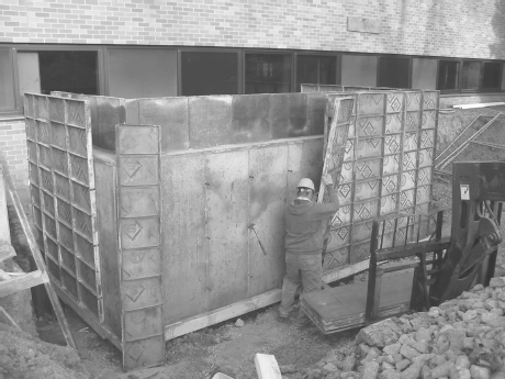
Figure 6.30 Removal of Modular Forms from a Cast-in-Place Reinforced Concrete Wall.
Source: M. Penn
FALSEWORK
Falsework is a temporary structure to support a structure during construction, until the structure is self-supporting. Concrete forms and supports are, in essence, simple types of falsework. For bridges and elevated roadways, more elaborate falsework may be required (see steel towers supporting elevated concrete roadway in the background of Figure 6.29), often supporting formwork for the concrete (Figure 6.31 and Figure 6.32).
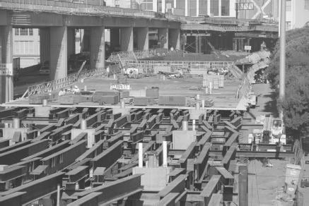
Figure 6.31 Falsework for an Elevated Roadway. The steel beams in the foreground are used to support the formwork for the concrete roadway deck. After the concrete cures, it will be self-supporting and the falsework will be removed. Note the permanent concrete structural support columns seen protruding through the falsework. These columns will be integrated into the deck structure.
Source: Courtesy of Caltrans, District 4 Photography/J. Huseby.
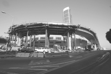
Figure 6.32 Falsework Seen from Below. The finished, self-supporting section of the elevated roadway is seen at right. Two permanent concrete supporting columns are seen within the temporary steel columns of the falsework.
Source: Courtesy of Caltrans, District 4 Photography/J. Huseby.
Utilities
Active construction often requires connecting to, or safely working around, existing utilities (e.g., natural gas, electric, fiber optic). “Call before you dig” is the mantra of utility providers. Location of utilities via spot painting and flagging; Figure 6.33) is critical before excavation commences. In fact, the location of utilities may affect design considerations (e.g., site layout to avoid conflicts with utilities). Do not rely on completed plans of previous projects or “hearsay” as to where utilities are located, as both of these sources are often incorrect. Even when utilities are “located,” surprises do occur; we have had several phone outages on our campus due to lines severed during construction of new buildings. The extension of utilities into new developments is an important phase of construction scheduling. Routing is typically parallel to the street in the right-of-way (Figure 6.34). Directional drilling is often used for utility placement under streets at intersections (Figure 6.35).
Figure 6.33 Flags and Paint Identifying Location of Utilities.
Source: M. Penn.
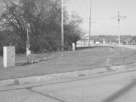
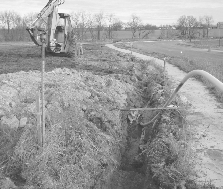
Figure 6.34 Natural Gas Line Placement in a Trench.
Source: M. Penn.

Figure 6.35 Directional Drilling of Utilities Under a Street. The worker (bent over) is using a sensor to locate the drilling head to relay information to the driller (foreground) to control the line of drilling. The drill will stop at the excavation on the opposite side of the street (see circled soil pile in background), where trenching will continue.
Source: M. Penn.
Erosion Control
Stormwater must be managed during active construction (post-construction stormwater management was discussed in Chapter 5, Environmental Infrastructure), and is often termed erosion control. Effective erosion control is imperative during construction because the existing vegetation and topsoil is generally removed at sites, leaving exposed subsoil that is prone to erosion during rainstorms. Without control measures, soil loss from construction sites can be orders of magnitude (e.g., 10x or 100x) greater than post-construction losses at the same site after new vegetation is established.
The most common erosion control method is the use of silt fences. When properly installed, it is a very effective means of preventing soil loss from a site. It does not prevent soil erosion, but merely keeps eroded soil from migrating off site during light to moderate storms. Very intense (low probability) storms will create high runoff rates, in which case the silt fence is often “uprooted” or “overtopped” and therefore ineffective (Figure 6.36). Unfortunately, without proper site inspection and enforcement to ensure correct installation and maintenance, it is not uncommon to see marginally effective or completely ineffective silt fences at construction sites (Figure 6.37). In some cases, contractors may be aware of damaged or inappropriate silt fences but choose to ignore them.
Silt fence acts as a filter, allowing water to pass through it while capturing soil particles.
A second erosion control method is a sedimentation basin (or sediment trap; Figure 6.38). Once filled with stormwater, the particles will settle to the bottom and accumulate in the basin. Basins are cleaned out with backhoes when they fill with sediment.
Sedimentation basins are depressions or dammed areas for the accumulation of storm runoff and the eroded soil carried with it.
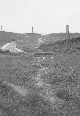
Figure 6.36 Soil-Laden Runoff Flowing Over Silt Fencing that was Overtopped During a Storm.
Source: M. Penn.
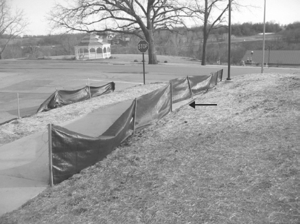
Figure 6.37 Improper Silt Fence Installation. The bottom of the silt fence should be trenched into the soil and backfilled. Note that stormwater can simply pass underneath this silt fence (which overlaps the sidewalk, see arrow) and no particulate removal will occur.
Source: M. Penn.
After rains, construction sites can become a muddy mess. Trucks and other equipment leaving the site carry mud with them onto the roads (called tracking; Figure 6.39). Tracking pads are areas of placed rock, typically at the site exit, to remove mud from vehicle tires (Figure 6.40). The rock needs to be replaced periodically to remain effective.
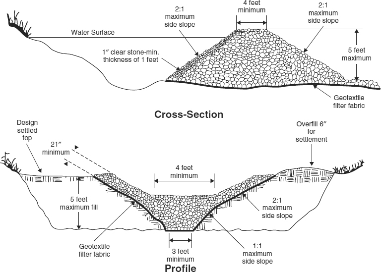
Figure 6.38 Cross-Section and Profile of a Sediment Trap. Geotextile filter fabric is placed under the stone dam to prevent erosion of the underlying soil as water seeps through the stone. Note that for cross-section view, water is moving from left to right, while for the profile view, water is moving “out” of the page.
Source: Dane County Office of Lakes and Watersheds, 2007.

Figure 6.39 Excessive Tracking of Material from a Construction Site onto Adjacent Road.
Source: M. Penn.

Figure 6.40 A Tracking Pad at the Exit of a Construction Site. Note the clumps of mud that lie on the pad and were removed from the tires of exiting vehicles. Also note minimal tracking onto the street.
Source: M. Penn.
Another erosion control method is the use of mulch or compost. Mulch is material placed on soil to prevent erosion. Without mulch, the raindrops easily dislodge soil particles from the soil surface making them free to erode (Figure 6.41). Mulching is typically applied after construction is complete and final topsoil has been placed and seeded (Figure 6.42). However, mulching can be used during construction as well.
Mulches include hay/straw and woodchips that dissipate the energy of falling raindrops.
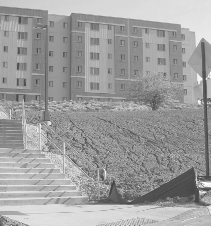
Figure 6.41 Erosion Channels Causing Soil Loss on an Unmulched Slope. Also note the unmaintained silt fencing at the base of the stairs.
Source: M. Penn.
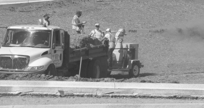
Figure 6.42 Straw Mulch Being Placed by a Bale Chopper/Mulch Spreader at a Road Construction Site Nearing Completion.
Source: M. Penn.
There are many other approaches to minimize construction site erosion, including non-physical practices (those that do not require construction or installation as needed with the above examples). For example, at a large site, site phasing may be used.
Site phasing is a method of construction whereby only areas of active construction are disturbed on an as-needed basis, rather than removing all topsoil from the entire site initially.
Outro
The success of the designs of engineers depends upon proper construction. Some engineers oversee the construction of their designs, whereas others rely on fellow engineers and construction managers. The cost and timeline of construction activities depends upon proper planning and construction equipment selection. Proper erosion control techniques can minimize the environmental impacts of active construction. Most employers of civil and environmental engineers look favorably upon construction experience because “having fought in the trenches” results in engineers that consider construction aspects of their designs.
chapter Six Homework Problems
Calculation
- 6.1 Based on the cross-section drawing in Figure 6.38, calculate the minimum base width of a 4-foot-tall stone dam for a sediment trap.
- 6.2 Consider the cross-section drawing in Figure 6.38. Using a 3:1 (horizontal-to-vertical) side slope and a 6-foot top width, calculate the base width of a 4-foot-tall stone dam for a sediment trap.
- 6.3 When soil is excavated and placed in a dump truck, the volume increases because the soil expands from its compacted natural state, typically by a factor of 1.25. How many dump truck loads (20-cubic-yard capacity) are needed to haul the soil from an excavation that is 30 feet wide by 50 feet long by 10 feet deep? Note: round your number of loads up to the next whole number.
- 6.4 Estimate (roughly) the capacity, or volume, of the bucket on the loader in Figure 6.12. Express your answers in cubic yards. Explain your assumptions.
Short Answer
- 6.5 Why is it important to “call before you dig?”
- 6.6 Give two examples of projects that would require a covered pedestrian walkway during construction. Give two examples of projects that would not require such a walkway.
- 6.7 Why might security check-ins be more likely at large construction sites than at small construction sites?
- 6.8 What is the primary advantage of directional drilling for utility placement?
- 6.9 Summarize methods to minimize soil loss from a construction site.
Discussion/Open Ended
- 6.10 Why do many cities have requirements for contractors to provide a detailed construction staging plan?
- 6.11 Summarize the requirements of the City of Sarasota, Florida, regarding construction staging plans (available at www.wiley.com/college/penn).
- 6.12 Why is scaffolding used to support construction workers, rather than the lift, in Figure 6.20?
- 6.13 As a summer intern for a city, one of your job responsibilities might be inspecting erosion control at construction sites. Describe your possible activities for this task.
- 6.14 A large dump truck has a greater hauling capacity and thus requires less hauling loads for a given excavation volume. What site conditions might cause a construction engineer to choose a smaller dump truck (requiring more hauls)?
Research
- 6.15 Use a program such as Microsoft PowerPoint to create a photo gallery that includes photos of each of the equipment types listed in this chapter. Make sure to provide references for photos obtained online.
- 6.16 Investigate and summarize the various types of attachments commonly used on excavators.
- 6.17 Investigate and summarize the various types of attachments commonly used on skidsteers.
Key Terms
- backhoes
- blasting equipment
- cement
- concrete
- concrete forms
- cranes
- dewatering
- dozers
- dump trucks
- earthmovers
- erosion control
- excavators
- falsework
- lifts
- loaders
- mulch
- piledrivers
- sedimentation basin
- silt fences
- site phasing
- skidsteers
- staging area
- tracking pads
- utilities
References
Dane County (WI) Office of Lakes and Watersheds. 2007. Dane County Erosion Control and Stormwater Management Manual, 2nd Edition.
http://danewaters.com/business/stormwater.aspx, accessed August 8, 2011.