
Chapter 4
Wireless LAN Client Devices
The following CWTS exam objectives are covered in this chapter:
- 2.2 Identify the purpose, features, and functions of the following client device types. Choose the appropriate installation or configuration steps in a given scenario.
- PC Cards (ExpressCard, CardBus, and PCMCIA)
- USB2
- PCI, Mini-PCI, Mini-PCIe, and Half Mini PCIe cards
- Workgroup Bridges
- Client utility software and drivers
Client devices are often thought of as computers—either desktop or notebook—connected to a computer network. However, there are many other devices, both wired and wireless, that can connect to a network. Wireless LAN client devices include various types of computers, tablets, smart phones, scanners, print servers, cameras, and other devices that are used to send data across the network. This chapter will look at the features of various wireless LAN client adapter types and the software for configuration and management of these devices.
Devices that connect to wireless networks use various types of adapters. Which adapter is used depends on the device that it connects to. You can connect wireless adapters to such devices as a notebook computer, tablet, desktop computer, or barcode scanner. Wireless LAN adapters are available in various types, both external and internal to the device. External adapters will connect to an available interface in the device such as a USB port or card slot. Examples of external adapter types are PCMCIA, ExpressCard, USB, and CompactFlash (CF).
Some devices use internal adapters that may require some level of disassembly or removal of a cover panel prior to the installation. Examples of internal adapter types are PCI, Mini-PCI, Full Mini-PCIe, and Half Mini PCIe.
Wireless LAN client adapters differ from other networking adapters (such as Ethernet adapters) because they contain radio hardware and use radio frequency (RF) to send the computer data over the air. Chapter 6, “Radio Frequency Fundamentals for Wireless LAN Technology,” will discuss RF fundamentals in more detail. A wireless LAN design should be partly based on the needs of the client applications, client device types to be supported, and the environment where they will be used.
Radio Hardware Used with Wireless LAN Technology
Wireless LAN client devices require some type of radio hardware or chipset to send the digital data (all the ones and zeros) across the air using radio frequency. It is important to understand that based on the IEEE 802.11 standard, every addressable unit used in a wireless LAN is considered a station (STA). This includes both client devices that connect to the network and wireless access points that allow devices to connect to and use network resources.
Another point to consider is that with the recent advancements in wireless LAN technology, including the release of the IEEE 802.11n amendment, client device selection will need to be carefully considered. Although it is beneficial to use 802.11n-capable client devices along with the newer 802.11n multiple-input multiple-output (MIMO) access points, radio technology used in 802.11a/b/g devices may benefit from MIMO technology as well. Selecting the correct wireless adapter will allow a user to take advantage of the newest wireless LAN technology available.
Many organizations now have to deal with the Bring Your Own Device (BYOD) issue. This is a trend in which employees bring their own personal electronic wireless devices such as tablets and Wi-Fi-enabled smart phones to the office or place of business. These devices will then have access to company resources, including email services, file servers, computer data, and printers. This may create problems for technical support and security issues. BYOD is forcing organizations to address this in corporate policies.
PCMCIA
PCMCIA technology was developed in the early 1990s because the portable computer industry demanded smaller, lighter, and more mobile technology. The international standards organization developed to promote the growth of such technology is the Personal Computer Memory Card International Association (PCMCIA). With the advancements in computer device technology, PCMCIA adapters are becoming less popular. In the early days of standards-based wireless LAN technology, it was common for a device such as a notebook computer to have an interface or a “slot” that allowed for the use of a PCMCIA adapter. With the advancements in technology, it is much less common to find a computer or device that supports this type of adapter than it was a few years ago. Most portable devices now use either a built-in wireless networking adapter or a USB adapter; both are discussed in this chapter.
Features of PCMCIA Cards
The PCMCIA standard addressed three types of cards—Type I, Type II, and Type III. These cards are named after the PCMCIA organization that promoted this card technology and was responsible for the standards. You might also see the term PC Card used to describe these cards; this refers to the physical card or peripheral. All three types are the same width and length and have a 68-pin connector.
Figure 4.1 shows an example of a PCMCIA card that allows a computer to connect to a wireless network.
The only difference among the three types of cards is their thickness. Table 4.1 lists the different thicknesses and common uses of the card types.
Figure 4.1 Netgear WN511T Wireless PCMCIA adapter
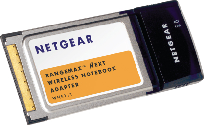
Table 4.1 Features of the three types of PCMCIA card
| Card Type | Thickness | Common use |
| Type I | 3.3 millimeters | RAM, flash, OTP, and SRAM memory cards |
| Type II | 5.0 millimeters | LANs, data/fax modems, and mass storage I/O devices |
| Type III | 10.5 millimeters | Rotating mass storage devices |
There are five versions of the PCMCIA standard. The release numbers are 1.0, 2.0, 2.1, 5.0, and 8.0. Releases 1.0 through 2.1 support 16-bit applications; releases 5.0 and up address a 32-bit interface.
![]()
Even with the advancements in this technology, there are still some devices in the marketplace that support PCMCIA adapters, and PCMCIA is included in the CWTS exam objectives. For that reason we'll next look at some details of its configuration.
![]()
Installation and Configuration of PCMCIA Cards
Installation of a PCMCIA card is a fairly simple process. The first consideration is to verify the physical characteristics of the card, such as the type (Type I, II, or III) and device in which it will be used—a notebook computer, for example. The card and the host device must be physically compatible with each other to ensure correct operation.
Another consideration is the device driver. A device driver is software required for a component such as a PCMCIA card to communicate with the computer or device operating system. The installer should have the latest version of the device driver accessible. The adapter usually comes with an installation CD that contains the device driver. It is best to follow the manufacturer's installation recommendations for the installation process, which may involve updating the driver from the manufacturer's website.
![]()
Configuration Using Installer Software
In many cases, a user will be required to first install a setup software program from the card manufacturer. This software will usually load the device driver within the computer operating system and install the configuration utility for the card.
Configuration Using a Wizard
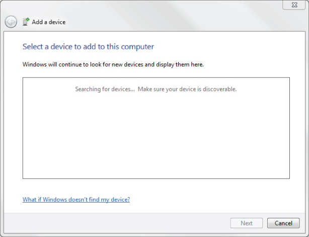
In some cases, when the PCMCIA card is inserted into the correct interface, the computer operating system will automatically install the required device driver. If the operating system cannot find the correct driver, the user will be prompted to search the Internet or insert a CD or other data source from the manufacturer with the software device driver. Figure 4.2 shows a wizard that the Microsoft Windows 7 Professional operating system will display to help load the device driver.
Figure 4.2 Microsoft Windows 7 Professional Add A Device Wizard
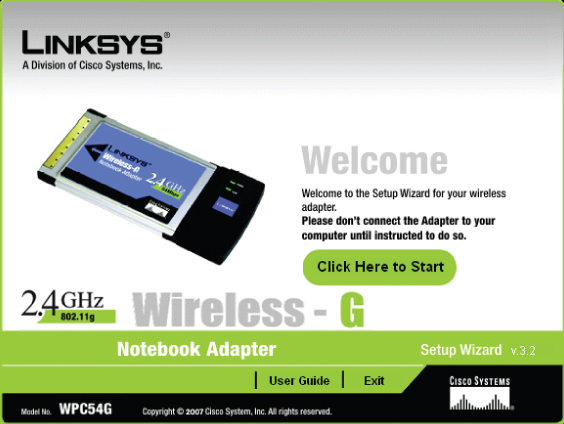
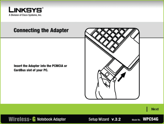
Exercise 4.1 illustrates how a common PCMCIA wireless LAN card will be installed. Do not insert the adapter until instructed to do so by the installation program. The manual device driver installation process described in Exercise 4.1 for PCMCIA is also applicable for other types of adapters explained in this chapter.
ExpressCard
ExpressCard is a newer generation of PC Card technology. This type of adapter is narrower than its predecessor (the PCMCIA adapter) and is available for newer wireless LAN technology, including IEEE 802.11n. Hewlett-Packard, Dell, Intel, and Microsoft are some of the PCMCIA member companies responsible for creating the ExpressCard standard. This technology is used in a large percentage of notebook computers to add new hardware capabilities. The ExpressCard is also used on some wireless LAN controllers and wireless access points to allow the addition of another radio, most often an Evolution-Data Optimized (EVDO) card to provide a backhaul for emergency use in high-availability roles.
Lower cost, smaller size, and higher performance were the driving forces behind ExpressCard technology. Applications include wired and wireless networking and communications, multimedia, and additional memory storage.
Features of the ExpressCard
The ExpressCard standard is built on the 16-bit and 32-bit PC Card standards. ExpressCard modules are available in four types: 34mm, 34mm extended, 54mm, and 54mm extended. The extended modules can be used for external connectors, television tuners, and wireless broadband, whereas standard modules will have specific functionality such as a wireless network adapter. Figure 4.3 shows the four types of available ExpressCards.
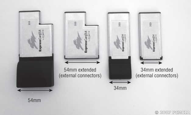
Users can install or remove an ExpressCard without having to power down the computer or device. This technology is known as hot-plug. Hot-plug technology is also commonly supported by USB and other adapters.
![]()
Installation and Configuration of an ExpressCard
The installation and configuration steps for an ExpressCard are similar to those for installing a PCMCIA card. (See the earlier section, “Installation and Configuration of PCMCIA Cards.”) Figure 4.4 shows an ExpressCard plugged into a notebook computer.
Figure 4.4 ExpressCard installed in a notebook computer
Image courtesy of PCMCIA. Used by permission.
USB 1.0, USB 1.1, USB 2.0, and USB 3.0
Introduced in 1995, the Universal Serial Bus (USB 1.0) standard was designed as a replacement for legacy serial and parallel connections.
Serial communication is the process of transmitting one data bit at a time. Parallel communication has the capability of transmitting several data bits at a time. Imagine a single-lane road compared to a four-lane highway. On a single-lane road, only one car at a time can travel, whereas on a four-lane highway, many cars can traverse the same path at the same time.
USB allows connectivity for various devices that once used serial and parallel data connection ports. These devices include but are not limited to:
- Keyboard
- Mouse
- Digital camera
- Printer
- Computer networking adapter
USB 1.0 specified data rates from 1.5 Mbps to 12 and was replaced by USB 1.1 in 1998. Devices using this version of the standard were more common in the market.
USB standards are implemented by the USB Implementers Forum (USB-IF). This organization consists of companies from the computer and electronics industries, including Intel, Microsoft, NEC, and HP.
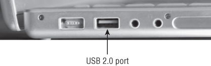
The USB 2.0 specification was released in April 2000. The first revision appeared in December 2000, and the standard has been revised several times since. USB 2.0 incorporates several changes, including connector types. Data rates now allow for a maximum speed of up to 480 Mbps (USB 1.0 supported a maximum of 12 Mbps).
Figure 4.5 shows an example of a USB 2.0 port.
Figure 4.5 USB 2.0 port on notebook computer panel
USB 3.0 technology was introduced in early 2010 and is commonly available to the point of being included on newer system boards. USB 3.0 devices have faster transfer rates and use a wider bandwidth, and they allow multiple logical streams and improved bus use with asynchronous readiness notification without polling. USB 3.0 greatly increases the transmission speed from the 480 Mbps of USB 2.0 up to 4.8 Gbps. This is more than 10 times that of the earlier standard, and as a result USB 3.0 is known as “SuperSpeed.” In addition to speed, the new USB 3.0 specification addresses improvements to the technology, including bandwidth, by using bidirectional data paths, power management, and improved bus utilization.
Features of USB
USB uses a standard connector that replaces 9-pin serial, 25-pin parallel, and various other connector types. External configuration allows the user to plug in the USB device and power it with a single USB port. The computer operating system will guide the user through the device driver installation process. External installation minimizes the need to open up a computer case and make adjustments within the computer such as switch or jumper settings. USB also supports hot-swapping of devices, allowing connection and disconnection without the need to power down the device or the computer. In some cases, USB allows for power to be delivered to the peripheral device, eliminating the need for an external power supply. Fewer and fewer devices are being built with PC card or ExpressCard interfaces and most use only USB ports for adding peripheral devices.
![]()
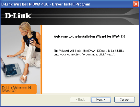
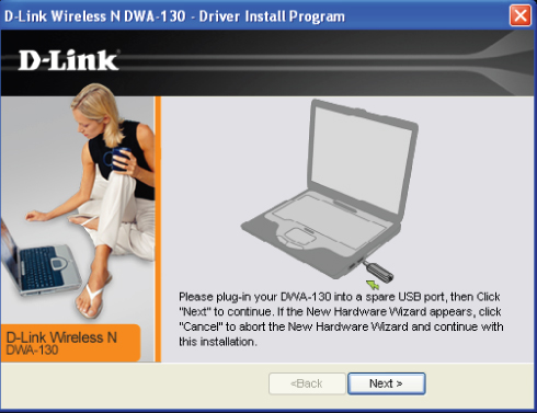
Installation and Configuration of USB Devices
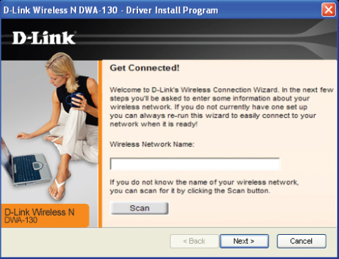
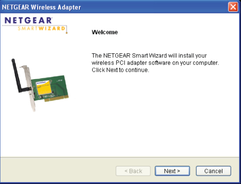
Exercise 4.2 walks you through the steps for installation of the D-Link Wireless N USB 2.0 adapter. Many USB wireless LAN adapters use installation procedures similar to this one. Installation steps are specific to the manufacturer, and I recommend that you follow the manufacturer's installation instructions. Always read the manufacturer's manual regarding installation and safety before attempting installation.
Peripheral Component Interconnect
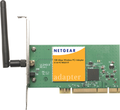
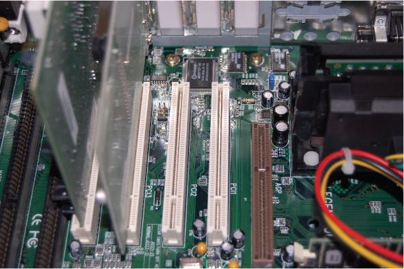
PCI is the acronym for Peripheral Component Interconnect, a standard for computer interface cards that was developed by Intel. A PCI card is inserted into a slot in the main board or motherboard of a desktop computer, allowing for the attachment of peripheral devices. Installing a PCI card may require basic tools such as a screwdriver, and the installer usually will need to remove the cover from the desktop computer case. Figure 4.6 shows an example of an IEEE 802.11 wireless PCI card.
Figure 4.6 Netgear WG311T IEEE 802.11g wireless PCI adapter
Features of PCI
A PCI adapter connects to what is known as a data bus in a desktop computer. In basic terms, a data bus allows connection of devices to the computer's processor or “brain.” In the early days of personal computers, many devices used a data bus. These devices included video, hard disks, serial ports, Ethernet adapters, and parallel ports for printers. These interfaces connected to what is known as an Industry Standard Architecture (ISA) bus.
Modern computers have integrated many of these interfaces directly into the motherboard, system board, or main board. As PC technology evolved, so did the data bus architecture, going to 32-bit and now 64-bit bus. Wireless networks are no stranger to PCI. Even though wireless is often thought of as portable or mobile, in many cases stationary desktop computers can utilize wireless LAN connectivity through the use of wireless PCI interface cards.
![]()
Installation and Configuration of PCI Cards
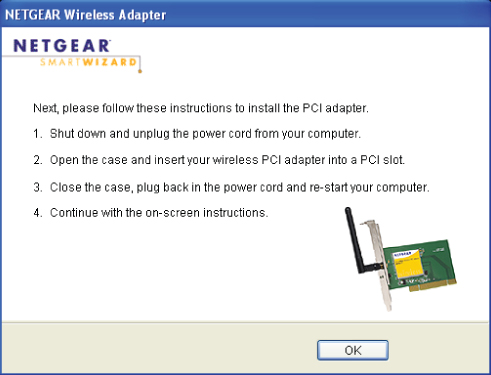
Back in 1995, Microsoft introduced a feature in the Windows 95 operating system called Plug and Play (PnP). This new feature accelerated the interest in PCI. PnP made installing a PCI card a snap. All that was required was for the installer to plug the card into the motherboard and it would be recognized and automatically work with the operating system. However, this process still required user intervention to open the case in order to physically install the card. Exercise 4.3 describes the steps for installing a PCI card in a desktop computer.
Mini-PCI, Mini-PCIe, and Half Mini-PCIe
Mini-PCI is a variation of the PCI standard, designed for laptops and other small-footprint computer systems. One common example of a Mini-PCI card is the IEEE 802.11 Mini-PCI adapter shown in Figure 4.7.
Figure 4.7 IEEE 802.11 Mini-PCI adapter
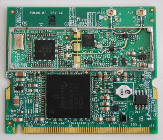
Mini-PCI cards are common in many devices, such as Fast Ethernet networks, Bluetooth, modems, hard drive controllers, and wireless LANs. In the wireless world, Mini-PCI cards are used in access points and client devices such as laptop or notebook computers.
Mini-PCI Express (Mini-PCIe) cards are a replacement for the Mini-PCI card and are based on PCI Express.
![]()
Features of Mini-PCI, Mini-PCIe, and Half Mini-PCIe Cards
Mini-PCI cards are available in three types; Type I, Type II, and Type III. Types I and II use a 100-pin stacking connector. Type III cards use a 124-pin edge connector. Type II cards have RJ11 and RJ45 connectors for telephone and Ethernet network connections. These cards are commonly located at the edge of the computer or docking station so that the connectors can be mounted for external access, such as to a modem or computer network.
Mini-PCIe cards are 30mm × 56mm and have a 52-pin edge connector, consisting of two staggered rows on a 0.8mm pitch. These cards are 1.0mm thick excluding components. Table 4.2 summarizes the features of Mini-PCI and Mini-PCIe cards.
The Half Mini-PCIe cards are 30mm × 31.90mm. The main difference between this card and the Mini-PCIe card mentioned earlier is the length. The length of this new form factor is about half of the Mini-PCIe card.
![]()
Table 4.2 Features of Mini-PCI, Full Mini-PCIe, and Half Mini-PCIe cards
| Card type | Connectors | Size |
| Mini-PCI Type IA | 100-pin stacking | 7.5mm × 70mm × 45mm |
| Mini-PCI Type IB | 100-pin stacking | 5.5mm × 70mm × 45mm |
| Mini-PCI Type IIA | 100-pin stacking, RJ11, RJ45 | 17.44mm × 70mm × 45mm |
| Mini-PCI Type IIB | 100-pin stacking, RJ11, RJ45 | 5.5mm × 78mm × 45mm |
| Mini-PCI Type IIIA | 124-pin edge | 5mm × 59.75mm × 50.95mm |
| Mini-PCI Type IIIB | 124-pin edge | 5mm × 59.75mm × 44.6mm |
| Full Mini-PCIe | 52-pin edge, two staggered rows on 0.8mm pitch | 30mm × 31.90mm × 1mm (excluding components) |
| Half Mini-PCIe | 52-pin edge, two staggered rows on 0.8mm pitch | 30mm × 56mm × 1mm (excluding components) |
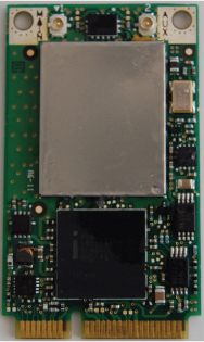
Figure 4.8 shows a Mini-PCIe adapter.
Figure 4.8 Intel 3945 IEEE 802.11a/b/g Full Mini-PCIe adapter
Installation and Configuration of Mini-PCI, Full Mini-PCIe, and Half Mini-PCIe Cards
As with the PCI card installation process, Mini-PCI and Mini-PCIe installation may require the user to physically install hardware in the computer. Location of the Mini-PCI or Mini-PCIe interface varies depending on the computer manufacturer. On some computers you just have to remove a cover panel on the bottom of the notebook. On others you need to disassemble the computer case. Exercise 4.4 describes the typical installation steps.
![]()
Additional Adapter Types
The following section describes some additional wireless radios and adapters. These adapters are not as common as some of the others mentioned earlier in this chapter but are still available for purchase and are used with networking devices. The following adapters were originally designed as memory storage cards but had a wireless network technology added to them:
- CompactFlash (CF) devices
- Secure Digital (SD)
CompactFlash Devices
CompactFlash (CF) was originally designed as a mass storage device format used in portable electronic devices. SanDisk introduced this format in 1994. The CF format is now used for a variety of devices and technologies, including Ethernet networks, Bluetooth, digital cameras, RFID, and wireless LANs.
Features of CF Cards
CF cards are available in two types: Type I and Type II. Both types have the same length and width, 36mm × 43mm. The only difference is the thickness.
Table 4.3 lists physical characteristics and typical uses of CompactFlash cards.
Table 4.3 Characteristics and uses of CF cards
| Card type | Thickness | Common use |
| Type I | 3.3 millimeters | RAM, flash memory cards |
| Type II | 5.0 millimeters | Wireless LANs, microdrives |
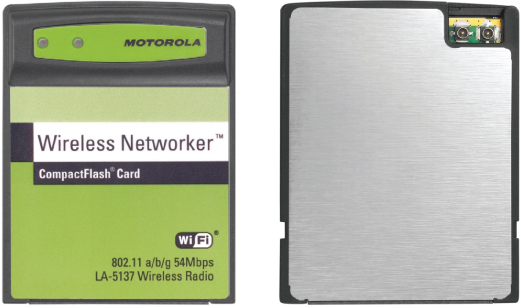
Figure 4.9 shows the front and back of a CompactFlash wireless LAN card supporting IEEE 802.11a/b/g wireless connectivity.
Figure 4.9 Motorola LA-5137 IEEE 802.11a/b/g CompactFlash card
![]()
Installation and Configuration of a CF Card
Installing a CF IEEE 802.11 wireless LAN card differs from some of the previous installation examples. For example, you may need to connect a handheld personal computer running a Microsoft operating system (Pocket PC) or personal digital assistant (PDA) to another computer in order to complete the installation process. Always follow the manufacturer's setup instructions for installing the specific card.
Secure Digital
Like the CompactFlash card, Secure Digital (SD) was designed as a flash memory storage device with storage capacities from 8 MB to 4 GB. The SD memory card was a joint venture among SanDisk, Toshiba, and Panasonic in 1999.
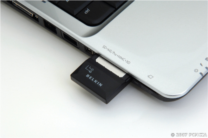
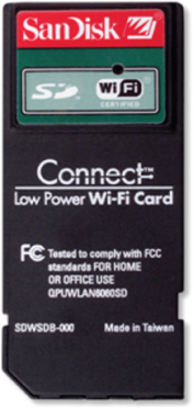
Even though the SD card was designed as to provide flash memory, the slot will allow for connection of other devices such as cameras, global positioning system (GPS) units, FM radios, TV tuners, Ethernet networks, and of course wireless LANs. In this format the SD card is known as Secure Digital Input Output (SDIO). This card is designed to provide high-speed data I/O with low power consumption for mobile electronic devices. Figure 4.10 is an example of an SDIO wireless LAN adapter.
Figure 4.10 SanDisk SDIO Wi-Fi card
Features of SDIO Cards
SDIO cards are available in two sizes:
- The full-size SDIO card is 24mm × 32mm × 2.1mm—approximately the size of a postage stamp. This SDIO card is intended for portable and stationary applications.
- The mini-SDIO is 27mm × 20mm × 1.4mm in size and used with wireless LAN and Bluetooth adapters.
![]()
Installation and Configuration of SDIO Cards
Installing an SDIO 802.11 wireless LAN card is similar to installing a CompactFlash card, and differs from the installation of PCMCIA and ExpressCard. These differences may include connecting a Pocket PC or PDA to another host PC running ActiveSync in order to complete the installation process. I recommend that you follow the manufacturer's setup instructions for installing a specific card. Here are the typical steps for installing an SDIO wireless LAN card:
![]()
Wireless Workgroup Bridges
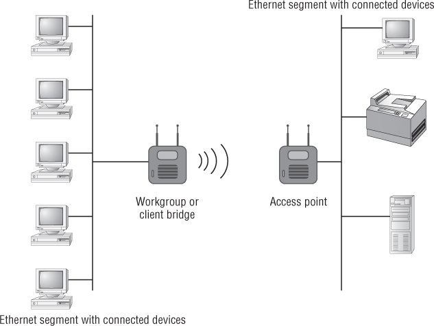
A wireless workgroup or client bridge is a wireless device acting as a client device that will allow potentially several Ethernet devices on an Ethernet segment (devices connected to a common physical layer boundary) to connect to an infrastructure through a wireless access point. This is accomplished without the need to upgrade each wired device on the Ethernet segment to wireless. Figure 4.11 illustrates an application of a wireless workgroup bridge.
Features of Workgroup/Client Bridges
The wireless workgroup bridge (WWB), also known as a wireless client bridge, can be used in a variety of business or SOHO applications, including enterprise, medical, retail, education, and warehouse. Supported devices include computers, printers, scales, medical equipment, barcode readers, and point-of-sale machines such as cash registers. Although the workgroup/client bridge may have the appearance and features of an infrastructure device such as a wireless access point, it is considered a client device. A workgroup bridge will allow for a limited number of wired client devices to connect to and use network resources. A wireless access point sees a wireless workgroup bridge as a single station even if several wired stations are connected, because the wireless workgroup bridge multiplexes the signal to a single wireless connection. In other words, it is basically a multiplex device.
Figure 4.11 Typical application for an enterprise wireless workgroup bridge
Wireless workgroup/client bridges may include these features:
- Fixed or detachable antennas
- Security features such as WEP, WPA, or WPA 2.0
- Web browser and/or command-line interface management utilities
- MAC filtering options
- Multiple connectivity modes
- Power over Ethernet
- Support for connection of a limited number of client devices
Installation and Configuration of Workgroup/Client Bridges
The following are the steps usually necessary for installing and configuring a workgroup or client bridge:
![]()
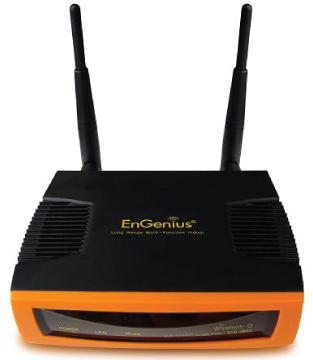
Another form of wireless client bridge is one that is designed to allow a variety of single Ethernet devices, not just computers, to connect to and use wireless networks. These devices will have an Ethernet port but are not wireless-capable. This type of client bridge also has characteristics similar to some infrastructure devices, such as wireless access points. One benefit is that in most cases no software is required; that is, you will not have to install device driver or client utility software on the client Ethernet device. These devices are seen by the access point as a single wireless client. Devices that can benefit from this type of client bridge are printers, DVD/media players, and game consoles. Figure 4.12 shows a wireless client bridge.
Figure 4.12 EnGenius Technologies ECB3500 802.11g High Power 600mW wireless access point/bridge/repeater/router
Client Device Drivers
All devices connected to a computer require a device driver. Components requiring drivers include keyboards, mice, video cards, USB ports, printers, wired network interface cards, IEEE 802.11 wireless LAN cards, and many others. The device driver is software that allows the installed device to communicate with or take instructions from the computer operating system in order to provide correct functionality.
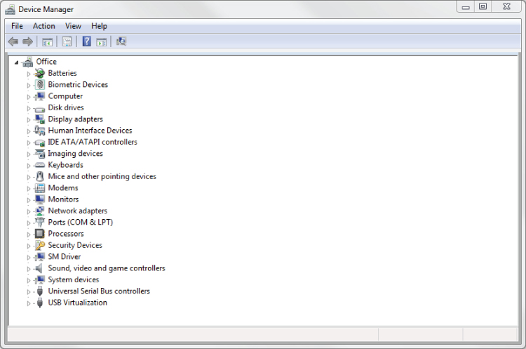
It is important to verify the latest revision of the device driver from the client device manufacturer. Having the latest revision installed will ensure correct operation and sometimes add additional features. Figure 4.13 shows a device listing in the Windows 7 Professional operating system.
Figure 4.13 Microsoft Windows 7 Professional Device Manager utility
Client Utility Software
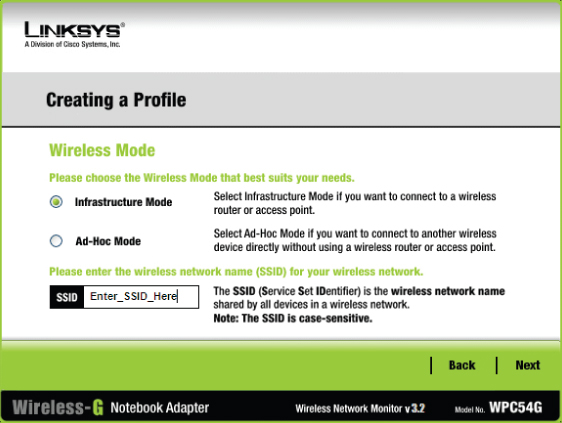
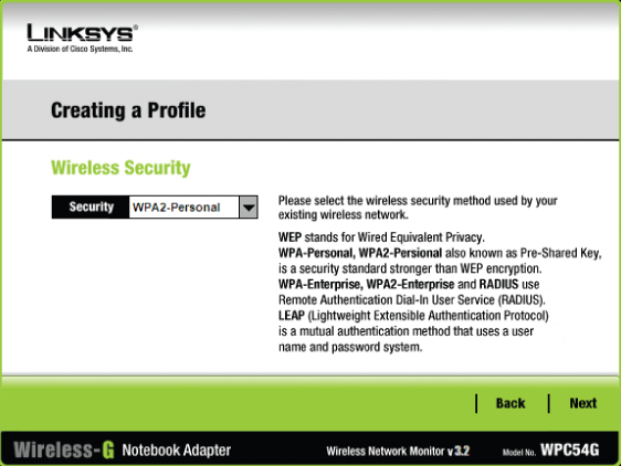
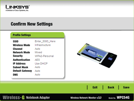
All IEEE 802.11 wireless LAN cards require configuration in order to connect to a wireless network. The configuration capabilities of device drivers are usually very limited. Therefore, a user needs additional configuration software. The user can choose from either manufacturer-specific utilities or third-party client utilities built into some operating systems. When IEEE 802.1X port-based authentication is used, the client device is known as the supplicant. The supplicant will provide authentication credentials to the authenticator, which in wireless networking is the access point. 802.1X authentication will be discussed in more detail in Chapter 9, “Wireless LAN Security Basics.” Regardless of the client utility installed, a user has the capability to create a profile that will retain the connection/session parameters. A profile will contain information regarding a specific connection, including network name or SSID and security settings.
Manufacturer-Specific Client Utilities
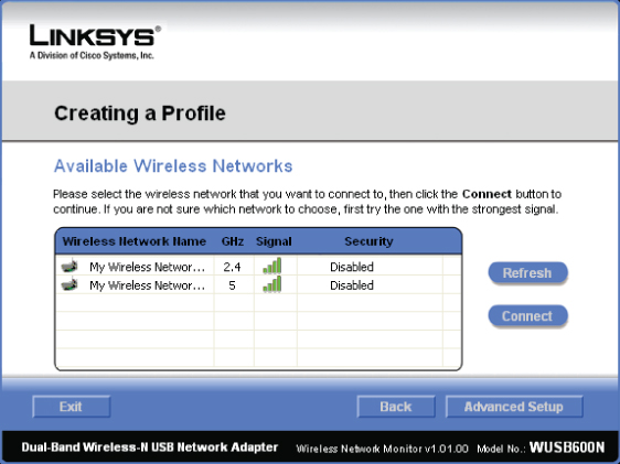
Most manufacturers of wireless LAN adapters provide a software client utility for the wireless adapter. The features of the utility depend on whether the client is SOHO grade or enterprise grade. SOHO grade client utilities have basic connection and security parameters. The client software installation usually is part of the adapter install process and is typically performed through a setup wizard. Figure 4.14 shows a screenshot from a SOHO client utility.
Figure 4.14 Linksys Dual-Band Wireless-N USB client utility
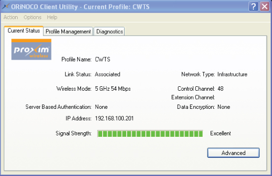
Enterprise-grade client utilities may have a more advanced feature set, including connection statistics and site survey. Typically, a user can install the device driver and client utility simultaneously or will be able to choose separate installation procedures. In most enterprise-grade client utilities, profile setup is a manual process requiring a user to have a basic understanding of the adapter's capabilities as well as the network configuration. Figure 4.15 shows an enterprise-grade client utility.
Figure 4.15 Proxim Client Utility for 8494-US 802.11a/b/g/n USB adapter
Third-Party Client Utilities
Another option for a wireless LAN adapter client utility is a third-party utility built into a computer operating system. Recent versions of the Microsoft Windows operating system—Windows XP Vista and Windows 7, for example—have a client utility built in and running as a service. In Windows XP this client utility is available from the Wireless Zero Configuration (WZC) service. Figure 4.16 shows the Windows XP WZC client utility.
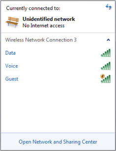
In later versions such as Windows 7, the service is now called the WLAN AutoConfig. After the wireless adapter is installed, a user may select a wireless network to connect to and supply security parameters if required. Figure 4.17 shows the Windows 7 Professional client utility using the Microsoft AutoConfig service.
Figure 4.16 Microsoft Windows XP WZC client utility
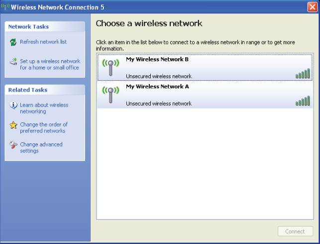
Figure 4.17 Microsoft Windows 7 Professional operating system client utility
Summary
There are many types of wireless LAN client devices used in various applications. These device types include desktop and notebook computers, printers, and barcode scanners, to name a few. A wireless client adapter uses radio hardware or chipset to send the digital data (all the ones and zeros) across the air using radio frequency. This chapter looked at some of the various IEEE 802.11 wireless LAN adapter types, explaining the features, common hardware, software, and configuration procedures. External adapters with wireless LAN functionality include:
- PCMCIA
- ExpressCard
- USB 2.0
- CompactFlash (CF)
PCMCIA adapters, although still available for purchase and used in many installations, are becoming less popular. Finding a newer notebook computer that has an interface to support a PCMCIA adapter is not as common. The PCMCIA Association has been dissolved and the San Jose office closed. This specification is now handled by the USB Implementers Forum.
Wireless LAN adapters are also available as internal adapters. These adapters may require some disassembly or removal of a panel for installation. Internal adapter types include these:
- PCI
- Mini-PCI
- Full Mini-PCIe
- Half Mini-PCIe
Wireless LAN adapters require a device driver in order to communicate with the operating system, and in most cases software utilities may be installed and/or configured in order to connect the wireless network. This chapter described several installation scenarios for various types of wireless LAN adapters, including PCMCIA, USB, and PCI. We also looked at how a wireless workgroup bridge can be used to connect computers and other devices on an Ethernet segment to a network by connecting to an access point.
Finally, this chapter showed how wireless LAN client utilities simplify the process of connecting to a wireless network. Client utilities are sometimes supplied by the manufacturer of the adapter or may part of the operating system. Windows Wireless Zero Configuration (WZC) or WLAN AutoConfig (Windows 7) is a commonly used operating system client utility.
Exam Essentials
Review Questions
1. You have a notebook computer and wish to connect to an IEEE 802.11n wireless network. The computer does not have a built-in wireless LAN card or a PC card interface. You do not want any peripherals connected to the notebook that use wires and do not want to disassemble the computer. Which wireless adapter would be the best solution?
A. Wireless PCI
B. Wireless PCMCIA
C. Wireless Full Mini-PCIe
D. Wireless USB 2.0
2. You need to select a wireless LAN card for a notebook computer to connect to an IEEE 802.11n network. The notebook has an interface or slot on the side that will accept one of three physical types of adapter. Which card would work best in this case?
A. PCI
B. Half Mini-PCIe
C. PCMCIA
D. ISA
3. In addition to wireless networking, which adapter was designed for flash memory storage and can be used in a digital camera?
A. PCI
B. PCMCIA
C. ISA
D. SDIO
4. A _____ computer requires the user to disassemble the computer case to install a wireless PCI network adapter. Which computer would be the best candidate in this situation?
A. Notebook
B. Desktop
C. Tablet
D. Barcode scanner
5. Which component is required for a successful installation and operation of an 802.11n wireless USB adapter?
A. Device driver
B. Client utility
C. Profile software
D. Windows WZC
6. You want to connect a desktop computer to an IEEE 802.11n wireless network. Which wireless LAN adapter would be the best solution if you do not want to disassemble the computer?
A. Mini-PCI
B. USB 2.0
C. Half Mini-PCIe
D. PCMCIA
7. Which client device will allow a user to connect several Ethernet devices on a common segment to an access point?
A. PCMCIA
B. PCI bridge
C. Wireless workgroup bridge
D. Ethernet bridge
8. USB was designed as a replacement for which two legacy communication connections?
A. Serial and PCI
B. Serial and parallel
C. Parallel and ISA
D. Parallel and EISA
9. How many data bits does serial communication transmit at a time?
A. 1
B. 3
C. 4
D. 8
10. Which wireless adapter may require some disassembly of a notebook computer to install?
A. PCI
B. PCMCIA
C. PC Card
D. Mini-PCI
11. Most manufacturers recommend installing a wireless IEEE 802.11n USB adapter at what point?
A. When the computer is not powered on
B. When instructed by the setup utility
C. After calling technical support
D. Before starting the setup process
12. Enterprise-grade IEEE 802.11g client utilities typically contain which advanced feature?
A. PCI configuration
B. Spectrum analyzer
C. Setup wizard
D. Site survey
13. Which item is required for an IEEE 802.11g PCI card to communicate with a computer connected to an unsecured wireless LAN?
A. Mini-PCI card
B. Device driver
C. Third-party utility
D. Enterprise utility
14. A wireless workgroup bridge will allow you to do which of the following?
A. Connect two wireless LAN NICs together.
B. Connect a wired LAN to an AP.
C. Connect a PCI card to a WLAN.
D. Connect two client bridges.
15. CompactFlash (CF) cards are available in two types. What is the main difference between the two types?
A. Length
B. Width
C. Thickness
D. Height
16. Which two wireless LAN adapters can be installed in a computer without the need to disassemble the computer in any way? (Choose 2.)
A. PCI
B. PCMCIA
C. USB 2.0
D. PCIe
E. Mini-PCI
17. Of all the devices listed, Secure Digital Input Output (SDIO) cards are most likely to be installed in which?
A. Desktop computer
B. Access point
C. Notebook computer
D. Pocket PC
18. A device driver can be used in wireless networking. Which is an example of a device driver?
A. Software to control a wireless NIC
B. Software to control the OS
C. Hardware to install a PCI card
D. Hardware to install a client bridge
19. Six wired clients can connect to a wireless LAN by using which device?
A. Workgroup bridge
B. PCI bridge
C. Mini-PCI adapter
D. PCI adapter
20. Which is required in order to successfully install an IEEE 802.11n wireless LAN adapter?
A. Security profile
B. Device driver
C. Third-party client utility
D. SOHO utility