4
Continuous Packet Connectivity and High Speed Common Channels
Harri Holma and Karri Ranta-aho
4.1 Introduction
WCDMA Release 99 was designed for large file transfers, not for frequent and bursty transmission of small packets such as those created by smartphones, see Chapter 13. The WCDMA air interface design is circuit switched like dedicated channels that are not optimized for efficiency, for latency, nor for terminal power consumption. High Speed Downlink Packet Access (HSDPA) in Release 5 and High Speed Uplink Packet Access (HSUPA) in Release 6 improved the efficiency, data rates, and latency considerably by providing a true packet channel-based radio interface. The limitation was still that a Dedicated Physical Control Channel (DPCCH) was required and setting up and releasing DPCCH takes time, adding to the connection setup latency and limiting the number of users with simultaneously active radio connections. We could say that the Release 6 solution was still circuit-switched from the control channel point of view.
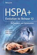
Release 7 brings Continuous Packet Connectivity (CPC) which enables Discontinuous Transmission (DTX) for the control channel. Release 8 brings for the first time a true packet-switched channel type in HSPA with High Speed Random Access Channel (HS-RACH) for the uplink direction, called Enhanced Cell_FACH in 3GPP. The corresponding downlink channel High Speed Forward Access Channel (HS-FACH) was defined in Release 7. The evolution of the packet transmission in HSPA improves the network efficiency, terminal power consumption, and end user latency and reduces signaling load. CPC and HS-FACH complement each other nicely: CPC gives benefits also together with HS-FACH during Cell_DCH state. Additionally, CPC terminal penetration is far higher than HS-FACH penetration. These packet transmission improvements have changed WCDMA radio access from circuit-switched to packet-switched, which is important for smartphones. These solutions are illustrated in Figure 4.1 and described in this chapter. Section 4.2 explains CPC, Section 4.3 HS-FACH, Section 4.4 HS-RACH, and Section 4.5 further enhancements to HS-FACH and HS-RACH. Sections 4.6, 4.7, 4.8, and 4.9 show the benefit of these solutions in interference reduction, terminal power consumption improvement, signaling reduction, and latency optimization. The chapter is summarized in Section 4.10.

Figure 4.1 Evolution of packet transmission in WCDMA/HSPA
The relevant 3GPP references for CPC and HS-FACH are as follows: [1] is the technical report of CPC and gives an overview while [2–4] include detailed procedures. Simulation results are shown in [5–9].
4.2 Continuous Packet Connectivity (CPC)
The data channel in HSDPA and HSUPA is active only when data transmission is happening but the control channel (DPCCH) is active continuously. Continuous Packet Connectivity (CPC) brings the following improvements:
- – Discontinuous transmission (DTX) of DPCCH in uplink.
- – Discontinuous reception (DRX) of High Speed Shared Control Channel (HS-SCCH) in downlink.
- – Downlink transmission without a High-Speed Shared Control Channel (HS-SCCH).
These features are applicable in Cell_DCH state to improve the link efficiency and reduce the UE battery consumption when the data transmission is not contiguous.
Note that CPC requires also one underlying feature called the Fractional Dedicated Physical Control Channel (F-DPCH) where the downlink DPCH can be shared by ten users to minimize the control channel overhead. F-DPCH was defined in Release 6 but it was implemented in practice only together with CPC in Release 7. The Release 7 functionality also brought enhancements to F-DPCH including more efficient operation in the case of soft handover and it is called enhanced F-DPCH (eF-DPCH).
CPC was defined already in Release 7 but it took a relatively long time to get the CPC feature working properly in the commercial networks. The main reason was that there were many parameters to be defined and to be tested in CPC, and it turned out to be a complex task to get all the chip sets and networks performing well together and achieving very low call drop rates. CPC terminal penetration in many networks is 10–15% as of 2013 and it is expected to increase rapidly with many new phones supporting CPC.
4.2.1 Uplink DTX
The CPC concept in uplink is illustrated in Figure 4.2. The uplink Enhanced Dedicated Physical Data Channel (E-DPDCH) runs only when there is data transmission in uplink while DPCCH runs also during data inactivity in Release 6. The typical inactivity timer before the channel is released and the UE moved to Cell_FACH or to Cell_PCH is several seconds. CPC allows using discontinuous DPCCH transmission during data inactivity when DPCCH is transmitted only in short bursts. These short bursts of DPCCH are needed to maintain the link synchronization and power control for instantaneous resumption of the data traffic. The discontinuous transmission brings two main benefits: less interference is created in the network and less battery power is used by the terminal.
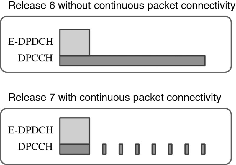
Figure 4.2 CPC concept in uplink
Typical CPC parameter values are shown in Table 4.1 both for 2-ms TTI and 10-ms TTI. Normally, 2-ms TTI is used as long as the uplink link budget allows 2-ms TTI transmission. If the signal level gets low, then the connection is reconfigured to 10-ms TTI.
Table 4.1 Typical CPC parameters (subframe = 2 ms)
| Name | 2-ms TTI | 10-ms TTI |
| UE DTX Cycle 1 | 8 subframes | 10 subframes |
| UE DTX Cycle 2 | 16 subframes | 20 subframes |
| Inactivity threshold for UE DTX Cycle 2 | 64 subframes | 80 subframes |
| UE DPCCH burst 1 | 1 subframe | 1 subframe |
| UE DPCCH burst 2 | 1 subframe | 1 subframe |
| UE DTX long preamble | 4 slots | 4 slots |
| Inactivity threshold for UE DRX cycle | 64 subframes | 64 subframes |
| UE DRX cycle | 8 subframes | 8 subframes |
| MAC DTX cycle | 8 subframes | 10 subframes |
| CQI feedback cycle with CPC | 4 subframes | 5 subframes |
Two DTX cycles are defined to better adapt to the different application requirements. When UE enters DTX transmission, it first uses DTX Cycle 1 that has higher DPCCH transmission frequency than Cycle 2. If there is no activity, then UE enters Cycle 2 after the inactivity threshold. This concept with typical parameters is shown in Figure 4.3.
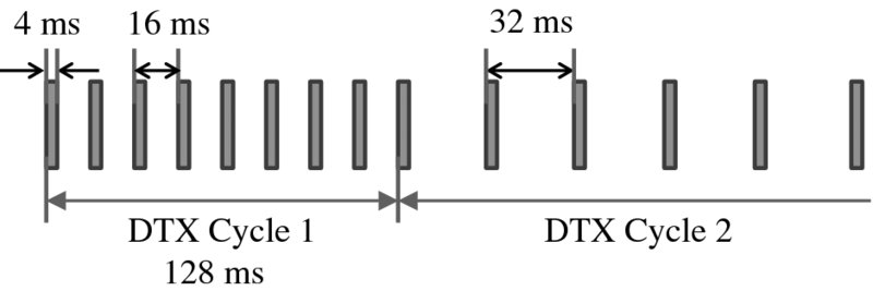
Figure 4.3 DTX Cycle 1 and 2 (CQI activity not considered during Cycle 1)
The transmission burst of a DTX cycle consists of a preamble, a burst of DPCCH, and a postamble, see Figure 4.4. Preamble and postamble are pilots before and after the DPCCH burst and they are used for channel estimation and uplink power control convergence. The preamble length is two slots and postamble length one slot. The actual DPCCH transmission burst is of configurable length and is typically the same with 2-ms and 10-ms TTI. A long preamble of 4 or 15 slots is also allowed in DTX Cycle 2 if E-DCH data transmission is started for better power control convergence after a longer transmission gap.
Figure 4.4 DPCCH transmission burst
The HSUPA uplink must maintain the correct received power levels with DTX operation too in order to prevent near–far problems when the data transmission on E-DCH is started again. The NodeB can estimate the uplink Signal-to-Interference Ratio (SIR) during the transmission burst. The power control command is sent on downlink Fractional DPCH (F-DPCH) to UE. There is no need to send any power control commands unless NodeB has updated the SIR estimate, in other words, if there is no transmission in the uplink in a particular slot, then there is no need to send power control commands in the corresponding downlink slot either. The power control process is illustrated in Figure 4.5.
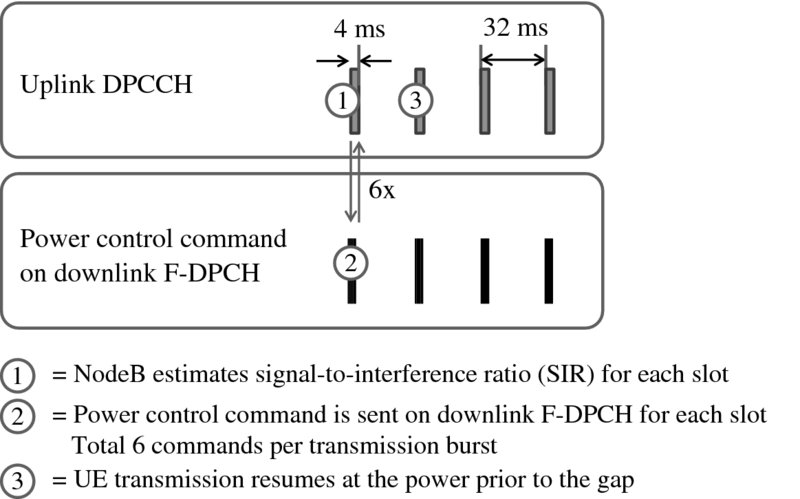
Figure 4.5 Uplink power control with DTX
The uplink HS-DPCCH transmission is needed to carry the control information related to the downlink transmission: HARQ acknowledgements (ACK/NACK) for retransmissions and CQI for the link adaptation. ACKs are transmitted in the same positions as without DTX; that means ACKs have higher priority than DTX and ACKs will cause additional uplink DPCCH activity. NodeB knows when to expect ACK because the offset between downlink transmission and uplink ACK is fixed. CQI is transmitted with normal periodicity if there has been HS-DSCH transmission during the last “CQI DTX Timer” subframes. If there has not been any recent HS-DSCH activity, then CQI is transmitted only when DPCCH is transmitted anyway. The idea is that CQI transmission does not increase the uplink activity unless it is needed due to simultaneous downlink activity. The CQI transmission with uplink DTX is illustrated in Figure 4.6.
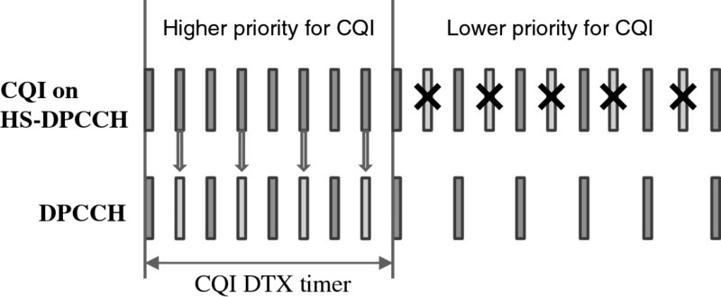
Figure 4.6 CQI transmission with uplink DTX
The DTX operation helps to reduce the uplink interference levels. The lower the transmission activity, the less interference is created to the network. The activity factor in DTX Cycle 2 is illustrated in Figure 4.7. The transmission burst length is 4 ms and the DTX cycle 32 ms with 2-ms TTI and 40 ms with 10-ms TTI leading to activity of 12.5% with 2-ms TTI and 10% with 10-ms TTI. These activity factors can lead to a substantial decrease in the uplink interference levels as shown in Section 4.6.
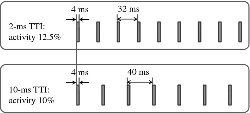
Figure 4.7 Activity factor in DTX Cycle 2
NodeB can configure UE specific offsets for DTX to spread the transmission interference equally in the time domain.
4.2.2 Downlink DRX
UE must monitor continuously up to four HS-SCCHs, E-AGCH, and E-RGCH in normal operation in the Cell_DCH state. The continuous reception keeps UE power consumption relatively high. Release 7 enables downlink discontinuous reception (DRX) to save UE batteries. If there has been no data to UE within the “Inactivity threshold for UE DRX cycle” number of subframes, the UE can start to use DRX. The “UE DRX cycle” defines how frequently UE must wake-up to check the HS-SCCH again to see if there is data scheduled to it. When there is again data transmission on HS-PDSCH, the UE needs to monitor the HS-SCCHs continuously in subsequent TTIs until the inactivity timer has expired. The DRX concept is shown in Figure 4.8.
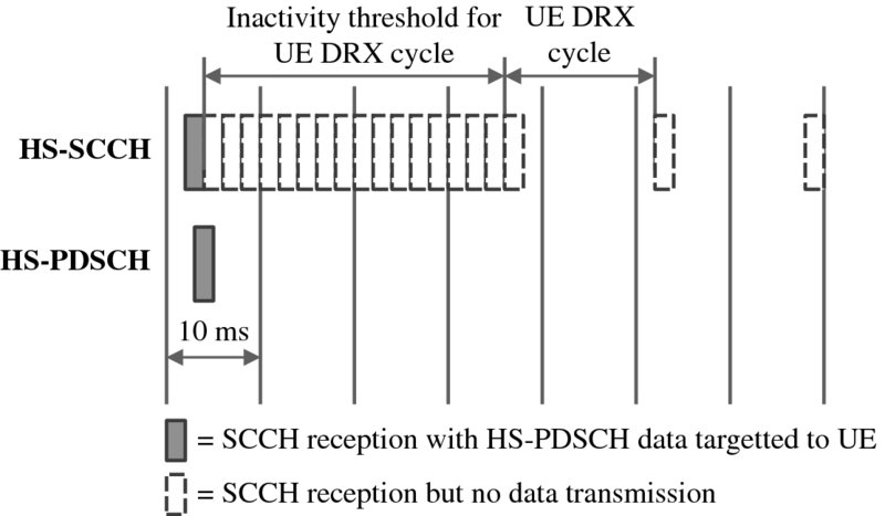
Figure 4.8 Downlink DRX concept
Downlink DRX only works together with uplink DTX because uplink power control is needed for uplink transmission. If uplink is running continuously, then the power control commands need to be delivered in downlink and DRX is not possible. That means uplink transmission also prevents downlink DRX. The concept is shown in Figure 4.9. It makes sense to harmonize the UE DTX cycle and UE DRX cycle parameters to maximize the benefits from downlink DRX power savings.

Figure 4.9 Downlink DRX with uplink activity
4.2.3 HS-SCCH-Less Transmission
The downlink control channel overhead was reduced considerably in Release 6 with Fractional DPCH (F-DPCH) where 10 downlink connections can share a single spreading code of length 256. F-DPCH needs to carry only the power control bits for the uplink. Release 7 allows further downlink optimization with HS-SCCH-less transmission of HS-DSCH data. The HS-SCCH overhead is low for large packet sizes but for small packets HS-SCCH-less transmission gives benefits. Such a service is, for example, Voice-over-IP (VoIP) with packet sizes typically below 50 bytes.
Transmission without HS-SCCH requires blind decoding of the HS-PDSCH by UE. A 24-bit CRC check masked with UE identifier is used on the HS-PDSCH transport block in HS-SCCH-less transmission. The identifier is called the HS-DSCH Radio Network Temporary Identifier (H-RNTI), which is normally used on HS-SCCH to identify the UE for which the transmission is intended. In order to keep the blind decoding complexity low, a few constraints have been defined for HS-SCCH-less transmission:
- – A maximum of four possible transport block sizes can be used.
- – A maximum of two HS-PDSCH codes can be used for data delivery.
- – Only QPSK modulation is allowed.
When HS-SCCH is used, then the UE knows when to expect data on HS-PDSCH. UE can then send either ACK or NACK in uplink depending on the decoding success of the data block on HS-PDSCH(s). The same approach cannot be used with HS-SCCH-less transmission: if UE decoding of HS-PDSCH fails, the reason could be that there was an error in the transmission, or that there was no data sent to that UE at all. Therefore, the UE cannot send NACK in HS-SCCH-less transmission at all. With failed decoding, the UE stores soft information in the memory to be used with potential retransmissions. The retransmission must always use HS-SCCH. HS-SCCH-less transmission is only possible for the first transmission. A maximum of two retransmissions are allowed together with HS-SCCH-less first transmission. The retransmissions with HS-SCCH are shown in Figure 4.10.
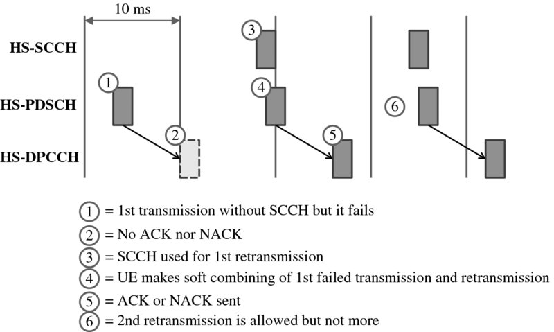
Figure 4.10 HS-SCCH-less transmission and retransmissions
The UE decodes the signal as follows in the case that HS-SCCH-less transmission is configured: first the UE checks if it can find HS-SCCH. If no HS-SCCH is found, the UE tries to decode HS-PDSCH with four different MCS hypothesis on the preconfigured HS-PDSCH codes. If HS-PDSCH decoding fails, the UE buffers these predefined HS-PDSCH codes to be combined with the potential retransmission. The retransmission must use HS-SCCH and it points to the first transmission, which allows the UE to make correct HARQ combining.
The HS-SCCH-less mode has a few benefits:
- – An increase in voice over HSDPA capacity because of the HS-SCCH overhead reduction.
- – More HS-SCCH capacity available for other simultaneous services.
These benefits help especially in downlink voice capacity but also in mixed voice and data traffic. Downlink VoIP simulation results with HS-SCCH and with HS-SCCH-less transmission are shown in Figure 4.11. The simulations assume 40 bytes of voice frame arriving every 20 milliseconds during active speech phase and a silence indicator packet arriving every 160 milliseconds during speech inactive phase with 50% voice activity. A single antenna Rake receiver and a maximum of six code multiplexed users are assumed in both cases. HS-SCCH is power controlled based on UE feedback. The results show that HS-SCCH-less transmission can increase VoIP capacity by 10%.

Figure 4.11 Capacity benefit of HS-SCCH-less transmission for voice case. Data from [8]
4.3 High Speed FACH
Release 99 RACH and FACH have very limited data rates: FACH 32 kbps and RACH in practice even less than 10 kbps when time spent on power ramping is considered. RACH and FACH are typically used to carry data volumes that are smaller than 512 bytes. HSDPA and HSUPA, on the other hand, require channel setup signaling and are better suited for larger packet sizes in excess of tens of kilobytes. HS-FACH and HS-RACH are designed to carry medium packet sizes and fill the gap between Release 99 common channels and HSDPA/HSUPA.
HS-FACH has many similarities with HSDPA with both using the HS-DSCH channel. The idea in HS-FACH is to take advantage of the advanced solutions already defined for HSDPA, like shared channel usage, NodeB based scheduling, link adaptation, and discontinuous reception. Figure 4.12 illustrates HS-DSCH with HS-FACH.
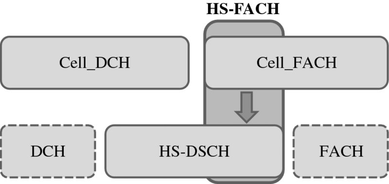
Figure 4.12 HS-DSCH usage in Cell_FACH state
There are some differences in Cell_DCH and Cell_FACH states: the first difference affects the CQI feedback and the acknowledgments. If HS-RACH transaction is ongoing, then HS-DPCCH can be used for the uplink feedback in the same way as in the Cell_DCH state. But if HS-RACH transaction is not ongoing and the UE is thus not allocated with uplink resources, then HS-DPCCH is not available either and no CQI nor layer 1 ACK/NACK feedback can be provided back to the NodeB. In that case only RLC level retransmission can be used. HS-FACH link adaptation can be controlled by RNC based on the UE reporting on RACH or based on the RLC retransmission frequency. The feedback solutions are shown in Figure 4.13. It is obvious that HS-FACH performance will be better if layer 1 feedback with HS-RACH is available. Fortunately, most of the packet sessions are uplink initiated and, therefore, the lack of uplink fast feedback is typically not a major issue, and even without uplink feedback, using shared HSDPA code and power resources the HS-FACH is a much more capable data delivery vehicle than FACH over S-CCPCH.
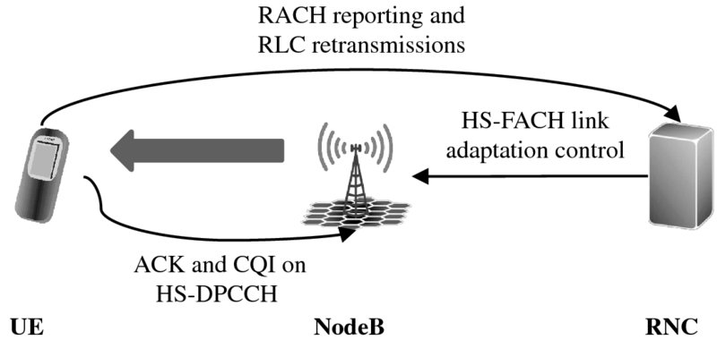
Figure 4.13 Feedback for HS-FACH link adaptation
HS-FACH performance with different retransmission approaches is illustrated in Figure 4.14. The file size of 100 kbytes is assumed to be transferred on HS-FACH, the link adaptation is based on the initial RACH measurement report and is not adjusted during the transfer of the file. To model the case with no HS-RACH allocation and no fast uplink feedback, a different number of fixed retransmissions (0… 3) are investigated. An upper bound of the no-feedback case is modeled with ACK feedback.
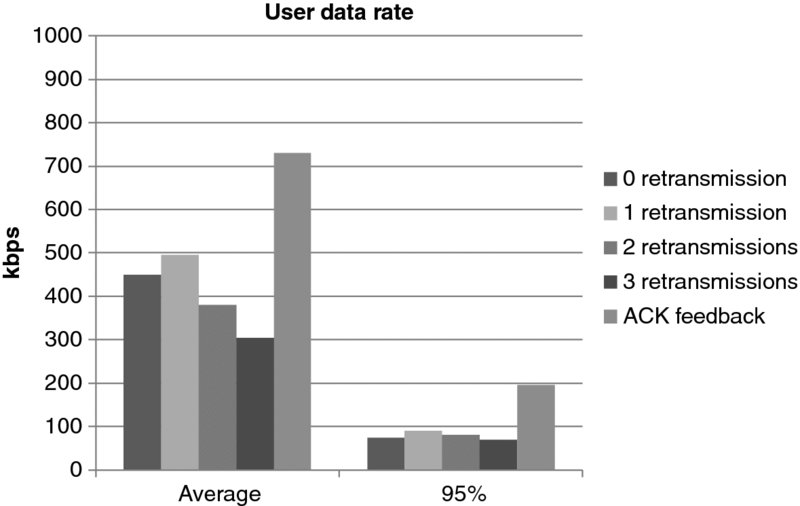
Figure 4.14 HS-FACH performance. Data from [9]
The Release 99 FACH throughput is typically 32 kbps and in practice even less when considering RLC retransmissions. With HS-FACH and no uplink feedback and always blindly retransmitting each packet once, the average throughput is close to 500 kbps already considering RLC retransmissions. A HS-RACH capability of 1.8 Mbps peak rate is assumed with five HS-PDSCH codes, QPSK-only modulation, and a single-antenna Rake UE. When the UE is allocated to HS-RACH, then fully-fledged HS-DPCCH feedback, with both HARQ-ACK and CQI, is available and the HS-FACH performance equals that of the Cell_DCH HSDPA performance.
HS-FACH brings a few important benefits:
- – Less interference by the small or medium size packet transmission than using FACH (no power control) or using HSDPA (setup signaling and DPCCH interference).
- – Less signaling than with HSDPA.
- – Lower latency for the end user.
- – Lower terminal power consumption.
- – Sharing of the same code and power resources between the Cell_FACH and Cell_DCH state users.
We also note that paging messages can be sent over HS-DSCH. This concept is called the High Speed Paging Channel (HS-PCH) and it increases the paging channel capacity considerably. The paging channel capacity in Release 99 is limited to below 100 paging messages per second in the case of 8 kbps PCH, and below 400 paging messages per second in the case of 24 kbps PCH. HS-PCH increases the paging channel capacity beyond these limits.
4.4 High Speed RACH
HS-FACH in Release 7 increased the downlink data rates in the Cell_FACH state but the uplink was still based on Release 99 RACH. It was obvious that a corresponding uplink enhancement was required: HS-RACH was included in Release 8. In practice, HS-FACH and HS-RACH are implemented together. HS-RACH follows the same logic as HS-FACH by using the already defined HSPA transport channels also in Cell_FACH state. HS-RACH uses the Enhanced Dedicated Channel (E-DCH) from HSUPA Release 6 which allows it to take advantage of link adaptation, NodeB based scheduling, and layer 1 retransmissions. The concept is shown in Figure 4.15.
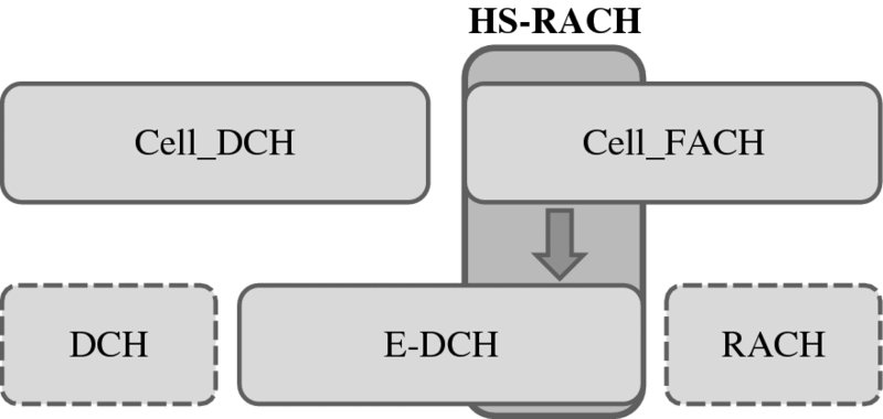
Figure 4.15 E-DCH usage in Cell_FACH state
HS-RACH signaling is shown in Figure 4.15.
- UE starts by sending Random Access Channel (RACH) preambles with increasing power levels. UE selects one of the preambles reserved for requesting E-DCH capacity.
- When the received power of the preamble exceeds the predefined NodeB internal threshold, NodeB sends layer 1 acknowledgement on Acquisition Indication Channel (AICH) pointing UE to the E-DCH resources with Extended Acquisition Indication (E-AI).
- UE starts transmission of control channels DPCCH and E-DPCCH and data channel E-DPDCH with initial data rate.
- UE is power controlled with downlink F-DPCH that is reserved for the corresponding E-DCH resources.
- NodeB commands UE to increase its data rate by using the E-DCH Absolute Grant Channel (E-AGCH). With E-AGCH the NodeB also confirms that the UE has passed collision resolution and may proceed.
- UE increases its data rate.
- NodeB sends layer 1 acknowledgement on E-HICH.
- Layer 1 retransmission can be utilized.
In short, HS-RACH transmission is the combination of the RACH access procedure with E-DCH transmission and rate control, and with power control on F-DPCH, as shown in Figure 4.16. With Release 8 the HS-RACH can be configured to either 2-ms or 10-ms TTI operation in a particular cell. Release 11 enhancement to HS-RACH enables the coexistence of both 2- and 10-ms TTI HS-RACH in the same cell and the TTI selection is taken based on the path loss at the beginning of the channel setup.
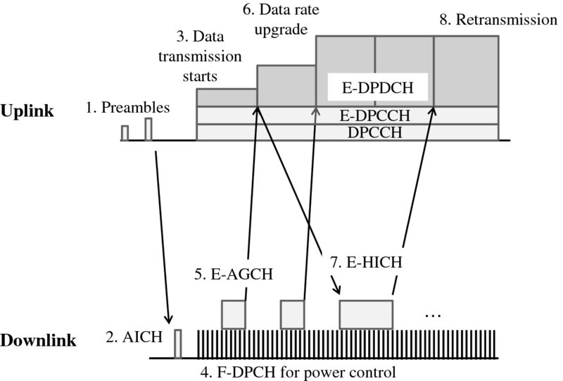
Figure 4.16 HS-RACH transmission
HS-RACH can enhance the common channel usage area. The maximum length of HS-RACH allocation is 640 ms. The allocation duration is limited because no handover is supported with HS-RACH and HS-FACH. If we assume a 0.5–2.0 Mbps data rate with HS-RACH and HS-FACH, the maximum data volume is 40 to 160 kB. That indicates that HS-RACH and HS-FACH are best suited for data volumes up to tens of kilobytes which extends common channel capabilities considerably compared to Release 99. Many smartphone applications create packet sizes that are higher than 512 bytes but less than tens of kB. The average data volumes per HS-DSCH allocation in smartphone dominated networks is 50–100 kbytes and the median values are far lower. The maximum data volume for Release 99 RACH is typically 256 or 512 bytes. Figure 4.17 illustrates the extended use of common channels with HS-RACH. Therefore, HS-RACH and HS-FACH are nicely suited to smartphone traffic.
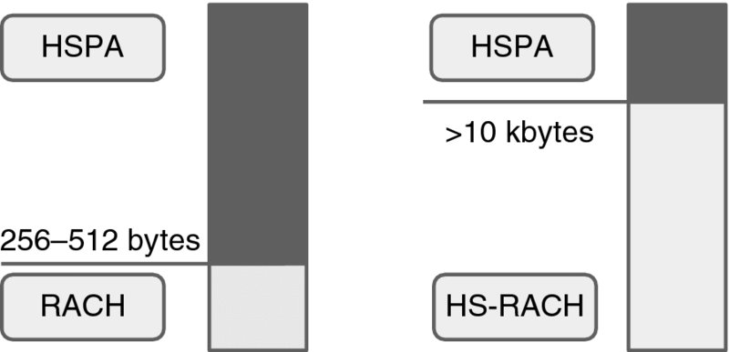
Figure 4.17 HS-RACH extends common channel usage
The main benefits of HS-FACH and HS-RACH can be summarized as follows:
- The same HS-DSCH and E-DCH channels are used as already defined for Cell_DCH state.
- Minimized uplink interference for small and medium size packets compared to Cell_DCH.
- Minimized signaling load compared to Cell_DCH.
- Very fast access to high data rates without setup latency.
- Reduced terminal power consumption.
WCDMA Release 99 defined a number of different transport channels for voice, data, signaling, common channels, and paging. HSPA Release 8 makes it possible to run all services on top of HSPA: Circuit Switched (CS) voice over HSPA is defined, packet data and VoIP can use HSPA, SRB can be mapped on HSPA, common channels can utilize HSPA channels with HS-FACH and HS-RACH, and also paging is supported on HSPA. The benchmarking of Release 99 and Release 8 is shown in Figure 4.18. It would be possible to get rid of all Release 99 channels and run just HSPA in the network if there were no legacy devices. The complete 3GPP specifications have been re-written by Release 8 with just a few remaining physical channels such as the Synchronization Channel (SCH), Common Pilot Channel (CPICH), Paging Indicator Channel (PICH), and AICH. These major changes also explain why HSPA evolution shows substantially higher performance than WCDMA Release 99. The major advantage is still that all these new HSPA features can be utilized on the same frequency as any legacy Release 99 terminal.
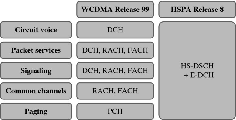
Figure 4.18 All services can run on top of HSPA in Release 8
4.5 High Speed FACH and RACH Enhancements
3GPP Release 11 brought a number of enhancement options on top of the Release 7/8 HS-FACH/HS-RACH. These features are collectively known as Further Enhanced FACH (FE-FACH).
NodeB triggered HS-DPCCH feedback for HS-FACH allows for the NodeB to send a HS-SCCH order triggering the UE to initiate HS-RACH procedure and establish a HS-RACH connection without waiting for the data in the uplink transmit buffer to trigger this. This feature can be used to obtain HS-DPCCH feedback for the HS-FACH transmissions as well as preemptively setting up the HS-RACH link before the uplink data transmission need occurs.
Concurrent 2-ms and 10-ms TTI HS-RACH deployment enables the coexistence of 2-ms and 10-ms TTI HS-RACH in the same cell. The TTI selection is done in the PRACH preamble ramp-up phase, if the preamble power required for acquisition is below a threshold a 2-ms TTI can be used, otherwise 10-ms TTI is selected.
Fallback to Release 99 RACH was introduced to help with HS-RACH resource blocking. The NodeB needs to allocate separate resource pools for Release 99 RACH and HS-RACH access, and if all the HS-RACH resources are already allocated it may be beneficial to direct a new access attempt to Release 99 RACH rather than reject it.
TTI alignment and per-HARQ process grants for 2-ms TTI HS-RACH enable time-aligning of the TTIs of different HS-RACH UE transmissions, and time-aligning HS-RACH transmissions to Cell_DCH HSUPA transmissions, and also controlling the activity states of the HARQ processes independently in the Cell_FACH state. These modifications make the 2-ms TTI handling of Cell_FACH and Cell_DCH UEs equal and makes it easier to manage the UEs' transmissions in time domain.
A second, longer DRX cycle in Cell_FACH allows for the UE to fall back to a longer DRX cycle in the Cell_FACH state after a period of inactivity. This makes the battery efficiency of the Cell_FACH state comparable to that of Cell_PCH state making it possible to keep the UE longer in the Cell_FACH state without penalizing the UE standby time.
PRACH preamble delay reduction redefined the time-domain randomization algorithm for the first PRACH preamble to minimize the latency. This optimization relates to UE implementation only and does not require any changes in the network.
Common E-RGCH based interference control enables the UEs to monitor E-RGCH channels during HS-RACH transmissions in exactly the same way as is done with HSUPA transmissions in Cell_DCH state during soft handover.
Network controlled mobility to LTE in Cell_FACH enables the network to configure the UE to measure the LTE frequency layer and report the results to the network in Cell_FACH and leave the decision to move the UE to LTE to the network's algorithms. The interworking between HSPA and LTE is presented in detail in Chapter 15.
Absolute priority cell reselection to LTE and inter-frequency UTRAN enables triggering of the inter-frequency and inter-RAT (to LTE only) mobility measurements and cell reselection in Cell_FACH state even if the current cell quality is good.
4.6 Fast Dormancy
Before the networks activated all power saving features, like Cell_PCH and CPC, some terminals implemented a proprietary solution to minimize power consumption. The idea was to release the RRC connection and go to idle state without any network control. Such a solution is referred to as proprietary fast dormancy. Proprietary implementation means that it was not defined in 3GPP specifications. Fast dormancy was used particularly if the inactivity timer in Cell_DCH was configured for too long, for example more than 5 seconds. When using such a fast dormancy, the mobile application informs the radio layers when the data transmission is over, and the UE can then send a Signaling Connection Release Indication (SCRI) to the RNC, simulating a failure in the signaling connection. Consequently, the UE releases the RRC connection and moves to idle state. This approach keeps the UE power consumption low, but it causes frequent setups of packet connections, increasing unnecessarily the signaling load. In addition to the high signaling load, the network counters indicate a large number of signaling connection failures as this battery saving method cannot be distinguished from a genuine signaling connection failure in the network.
3GPP Release 8 specified a fast dormancy functionality clarifying the UE behavior and providing the network with information on what the UE actually wants to do, but leaving the network in control of the UE RRC state. That is, the UE is not allowed to release the RRC connection and move to an idle state on its own without network control. When the RNC receives SCRI from a UE with a special cause value indicating a packet data session end, the RNC can command the UE to Cell_PCH state instead of releasing the RRC connection and dropping the UE to idle state. This approach avoids unnecessary Radio Access Bearer (RAB) setups and enables the network to separate signaling connection failures from fast dormancy related signaling connection release indications. The Release 8 fast dormancy feature helps to save UE battery when the radio layers get information directly from the application layer when the data transmission is over. The fast dormancy functionality is illustrated in Figure 4.19.
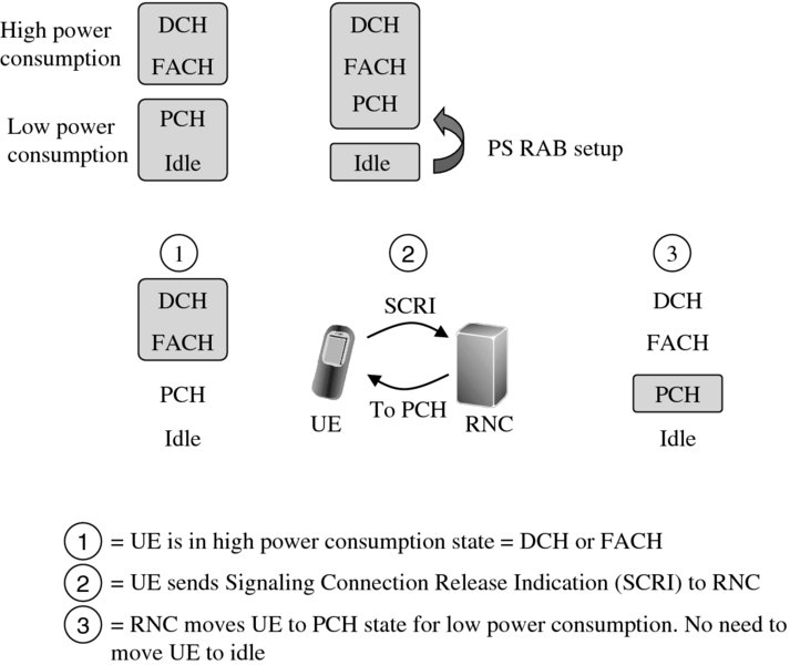
Figure 4.19 Release 7 fast dormancy functionality
The signaling messages in the state transitions are shown in Figure 4.20. The messages include Radio Resource Control (RRC), NodeB Application Part (NBAP), Access Link Control Application Part (ALCAP), and Radio Access Network Application Part (RANAP). RRC messages run between RNC and UE. NBAP and ALCAP messages are transmitted between RNC and NodeB, and RANAP between RNC and packet core. If UE is idle, a total of 30 messages are needed to get to Cell_DCH state. If UE has a RRC connection and is in Cell_PCH state, 12 messages are required to get to DCH state. If UE is in Cell_PCH state and has a low amount of data that can be carried over FACH, then the transition to Cell_FACH takes only three messages. There is a major benefit from the signaling point of view to remain RRC connected instead of moving to idle.
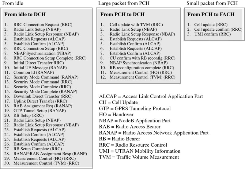
Figure 4.20 Signaling messages in state transitions
The network broadcasts an inhibit timer (T323), setting a minimum delay between the two SCRI messages for fast dormancy a UE is allowed to send. This is to prevent a UE from sending a constant flow of SCRI messages if for some reason the network is temporarily unable to move the UE to a battery saving state. The presence of T323 in the broadcast can also be considered an indication of network support of the fast dormancy functionality, triggering the UE to use the SCRI messages with the cause value indicating the packet data session end. 3GPP standard based fast dormancy was defined to be early implementable, that is, even though the behavior and changes in the signaling are defined in the Release 8 specifications it was possible to build these extensions to a UE and network that is not Release 8 compatible. That approach allowed the quick introduction of the fast dormancy feature.
4.7 Uplink Interference Reduction
Smartphone applications tend to transmit small packets very frequently. The traffic behavior is analyzed in Chapter 13. The average data volume per HS-DSCH allocation can be below 100 kB but the allocations can happen 20 times per hour for an average user and with even higher frequency for active social networker users. If we assume a 5 Mbps data rate and 100 kB packet size, the transmission time is just 0.16 s. The typical inactivity timers are set to 2–10 s which means that more than 90% of the time the uplink DPCCH is running without any data activity (Figure 4.21). This explains why networks with high smartphone penetration suffer from uplink interference effects: smartphone devices keep transmitting unnecessarily in the uplink direction while the channel is up.
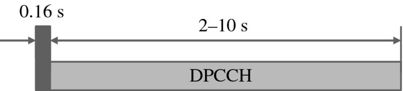
Figure 4.21 DPCCH causes uplink interference with small packet sizes
One of the main benefits of CPC is the reduced uplink interference due to DTX. The activity factors in Figure 4.7 are 12.5 and 10% for 2- and 10-ms TTIs. These activities would indicate in theory 8–10 times higher uplink capacity when the radio link is inactive and can fully utilize DTX. In practice, the expected uplink capacity gain is lower because power control accuracy is sacrificed during DTX. In order to find out the realistic gains, field measurements were run with a large number of terminals in Cell_DCH state but with very low activity. The maximum number of simultaneous users per cell is evaluated with 3 and 6 dB noise rises corresponding to 50 and 75% loadings. The testing was done with CPC off for all users and CPC on for all users. The 2-ms case is shown in Figure 4.22 and 10-ms case in Figure 4.23. The maximum number of simultaneous users per cell without CPC is only 25–50 even if the users are inactive. That means the uplink is fully congested by the control channels even if the cell throughput is zero. DTX improves the uplink capacity by a factor of 4 to 6 in the measurements. More than 200 simultaneous users can be supported per cell with DTX. The lower interference levels with DTX may allow extension of the inactivity timer for CPC users to keep the UE in the Cell_DCH state for a longer period. A longer inactivity timer could be beneficial from the end user performance point of view if the state transition can be avoided.
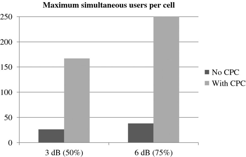
Figure 4.22 Measurements with 2-ms TTI
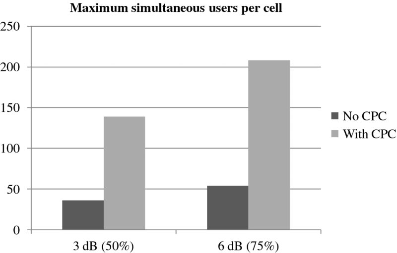
Figure 4.23 Measurements with 10-ms TTI
Next, we show how to turn these measurements into the estimated number of subscribers per cell depending on the application activity and packet size. The Release 6 case assumes that data is transmitted on HSUPA without CPC. Release 7 assumes DTX during the inactivity timer. Release 8 assumes that the data is carried by HS-RACH. We use the following further assumptions in the calculations:
- – Maximum load factor 75% = 6 dB noise rise.
- – Application packet arrival period 60 s.
- – Application packet size 0.5–64 kB.
- – HSUPA inactivity timer 4 s for Release 6 and Release 7.
- – HS-RACH inactivity timer 40 ms for Release 8.
- – Average HSUPA data rate 384 kbps.
- – Average HS-RACH data rate 384 kbps.
- – HSUPA E-DPDCH (data) vs. DPCCH (control) offset 9 dB. E-DPDCH Eb/N0 requirement 2 dB.
- – DPCCH interference reduction with DTX -75%, that means 4 times more capacity.
- – All terminals support Release 7 CPC and Release 8 HS-RACH, which is naturally optimistic in the short term.
The assumptions correspond to approximately 37 simultaneous users without CPC and 140 with CPC if they are all in Cell_DCH state, which is similar to the field measurements. Figure 4.24 shows the maximum number of subscribers per cell when the traffic model is considered. The maximum number of subscribers per cell with Release 6 is approximately 500. The number is not sensitive to the transmitted packet size because most of the interference is caused by the control channels, not by the data transmission. It is easy to understand that the network can get congested in mass events with tens of thousands of people each with smartphones. Assume 80 000 people in a large sports stadium. The operators would need a minimum 80 000/500 = 160 cells in the stadium to provide enough capacity. Since the spectrum is limited, they would need multiple sectors which again would increase the inter-cell interference and further reduce the capacity. Release 7 CPC brings nearly four times more capacity because most of the interference comes from inactive users and DTX helps a lot. The CPC gain is still two times with a packet size of ten kB. The gains with Release 8 HS-RACH are even more massive, since the transmission can be stopped very quickly when the data transmission is over. The relative gain of HS-RACH compared to Release 7 CPC is more than two times if the packet size is below 5 kB. With very small packet sizes, Release 8 HS-RACH can support even 10 000 subscribers per cell, which is 20 times more than with Release 6.
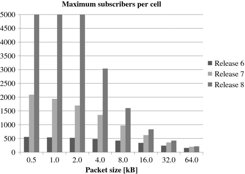
Figure 4.24 Maximum simultaneous subscribers per cell
Figure 4.25 shows the effective cell throughput as a function of the packet size. We can note that the cell capacity is very low with Release 6 HSUPA if the packet size is small. The cell throughput can be even below 100 kbps because the uplink is congested by the control channel interference. If we consider large file transfers, the cell throughput would be 1800 kbps with Release 6 with these assumptions. These calculations indicate that the uplink network dimensioning for smartphone applications can be challenging, especially with Release 6 devices, because the cell throughput can be far lower than in the traditional dimensioning.
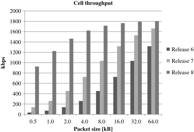
Figure 4.25 Effective uplink cell throughput
4.8 Terminal Power Consumption Minimization
The other major benefit from CPC and HS-FACH/HS-RACH is the terminal power savings. The actual power savings depend on multiple implementation choices in the devices. We present the reduction in the terminal transmit RF activity which is the upper bound for the power savings. We make the following assumptions in the calculations
- – Average HSUPA data rate 384 kbps.
- – Transmit RF activity during HSPA setup 200 ms.
- – Transmit RF activity during HS-RACH setup 10 ms.
- – HSPA inactivity timer 2 s.
- – DTX activity factor with Release 7 CPC 13%.
Figure 4.26 shows the RF active time for the transmission of small packets. Most of the RF activity with Release 6 happens during the 2-s inactivity timer. Release 7 RF activity is reduced considerably with DTX during the inactive time. Release 8 is still substantially more efficient especially for small packet transmission. The gains in terms of power consumption are lower because there are many other components in the terminal taking power. Power saving measures are shown in Chapter 14.
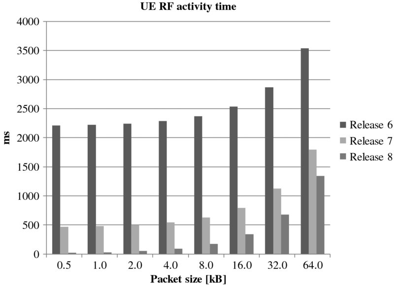
Figure 4.26 UE transmit RF activity time
4.9 Signaling Reduction
The number of RRC signaling messages can be reduced with HS-FACH and HS-RACH. Setting up and releasing the HSPA channel requires a minimum of four RRC messages over the air and two NBAP messages over Iub. In the case of HS-FACH and HS-RACH no RRC messages are required. The reduction in the signaling messages is generally beneficial from the network efficiency point of view. The signaling flow for the state transition to Cell_DCH is shown in Figure 4.27. All this signaling can be avoided when HS-FACH and HS-RACH are used for the data transmission.
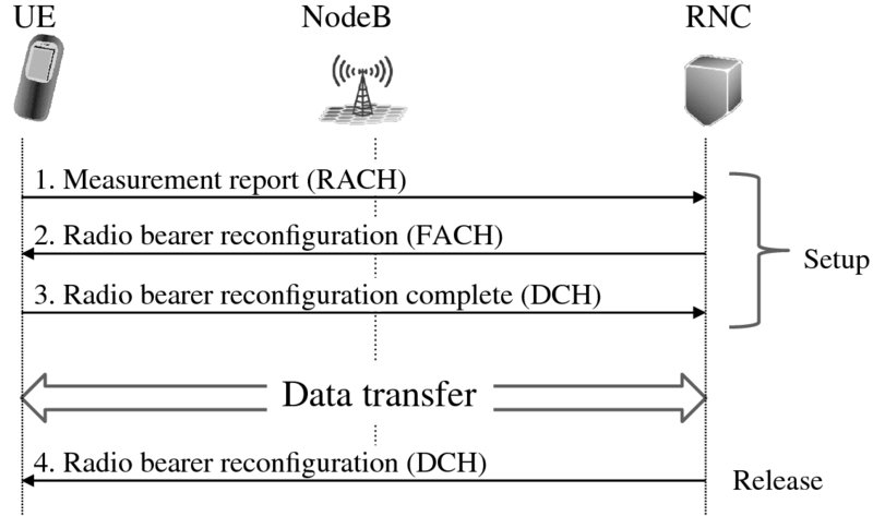
Figure 4.27 Signaling flow for state transition from FACH to DCH
Figure 4.28 shows the number of RRC messages per cell per second in a high loaded cell if every packet transmission requires HSPA channel allocation. The number of messages can be more than 100/s/cell in the case of small packet transmission. When HS-FACH is used, most of these RRC messages can be avoided.

Figure 4.28 Number of RRC messages for HSPA channel allocation without HS-FACH
4.10 Latency Optimization
HS-FACH and HS-RACH also improve the end user experienced response times. HSDPA/HSUPA make the download time very short but the channel setup time still increases the total response time. Assuming a HSDPA data rate of 10 Mbps, even the average web page of 1–2 Mbytes can be downloaded in 1–2 s without considering any TCP impacts. The state transition from Cell_FACH or from Cell_PCH to Cell_DCH takes typically 0.5 s. In practice, the application layer delay can be up to 2 s due to the state transition. HS-FACH and HS-RACH allow access to high speed data without any state transition delay. The end user latency benefit is illustrated in Figure 4.29.
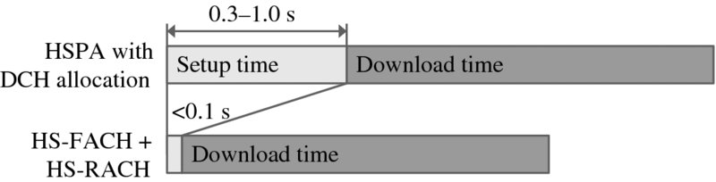
Figure 4.29 End user latency improvement with HS-FACH and HS-RACH
4.11 Summary
3GPP Releases 7 and 8 bring CPC and HS-FACH/HS-RACH functionalities that are important for the growing number of smartphone applications that tend to transmit small packets frequently. CPC includes uplink DTX, downlink DRX, and SCCH-less transmission. Uplink DTX reduces uplink interference up to a factor of four with small packet transmission. Uplink DTX together with downlink DRX helps in minimizing terminal power consumption. SCCH-less transmission optimizes downlink control channel usage and increases the maximum capacity. HS-FACH and HS-RACH further improve the efficiency of small packet transmission and the end user experienced latency. All these functionalities were introduced commercially to the networks and first devices by 2014. Further enhancements on top of HS-FACH and HS-RACH have been included in Release 11 specifications.
References
- 3GPP Technical Report 25.903 “Continuous connectivity for packet data users”, v. 7.0.0, 2007.
- 3GPP Technical Specification 25.214 “Physical layer procedures (FDD)”, v. 11.7.0, 2013.
- 3GPP Technical Specification 25.308 “High Speed Downlink Packet Access (HSDPA); Overall description; Stage 2”, v.10.6.0, 2013.
- 3GPP Technical Specification 25.319 “Enhanced uplink; Overall description; Stage 2”, v.11.7.0, 2013.
- 3GPP R1-061476 “TP on uplink 10 ms TTI VoIP capacity with UL DPCCH gating”, RAN1 meeting #45, 2006.
- 3GPP R1-061576 “UE tx and rx parts power consumption improvement with DTX and DRX”, RAN1 meeting #45, 2006.
- 3GPP R1-062249 “Further link simulation results for UL DPCCH gating, HARQ on”, RAN1 meeting #46, 2006.
- 3GPP R1-062251 “HSDPA VoIP capacity”, RAN1 meeting #46, 2006.
- 3GPP R1-063339 “Further analysis of HSDPA in CELL_FACH state”, RAN1 meeting #47, 2006.