7
Heterogeneous Networks
Harri Holma and Fernando Sanchez Moya
7.1 Introduction
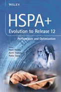
Heterogeneous Network (HetNet) refers to the joint optimization of different cell layers and technologies. Current mobile networks are based on wide area macro cells that provide several hundred meters of coverage, even tens of kilometers, and normally use three sectors per site. Small cells can be added to provide more capacity and coverage. These small cells can be outdoor small cells, public indoor small cells, or home or enterprise small cells. The outdoor small cells are often termed micro cells, indoor cells pico cells, and home small cells femto cells. The HetNet concept is shown in Figure 7.1.
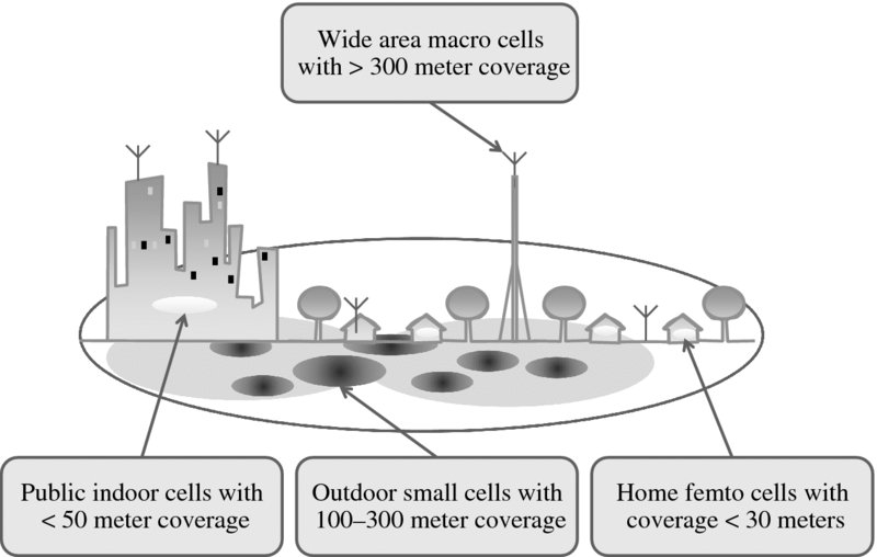
Figure 7.1 HetNet concept
The HetNet concept also considers the use of the different technologies GSM, HSPA, LTE, and WLAN together. This chapter focuses on HSPA small cell deployments together with existing macro cells on WLAN interworking. Section 7.2 presents the drivers for the small cell rollouts. Section 7.3 shows the base station categories. Sections 7.4 and 7.5 present the main challenges with HSPA HetNets – interference management and link imbalance, Section 7.6 studies the data rate and capacity benefits provided by the small cells, and Section 7.7 illustrates field deployment result with HSPA small cells. Femto cell architecture and optimization are discussed in Section 7.8 and WLAN interworking in Section 7.9. The chapter is summarized in Section 7.10.
7.2 Small Cell Drivers
The introduction of small cells is driven by capacity and coverage requirements. As data traffic increases in many HSPA networks, macro cells are getting congested and operators have used all their spectrum resources in them. Capacity could be enhanced by adding new macro sites or by adding new sectors to the existing macro sites. However, it may be difficult or expensive to find a location for a new macro site or to add more antennas to the existing sites. Therefore, the most practical way of increasing network capacity may be to add new small base stations. The small cells can also be deployed to improve the coverage and increase local data rates.
Small cells have been discussed in the industry for a long time but it is only recently that the implementation of small cells has become simpler for operators: the small base station products are very compact due to the evolution of digital and RF technologies, the network configuration and optimization is becoming automatic with Self Organizing Network (SON) solutions, and attractive wireless backhaul options are emerging.
The need for small cells may be postponed by the availability of new spectrum and LTE radio, which provide a lot more capacity with existing macro sites. The problem may still be that the LTE terminal penetration does not increase fast enough to migrate the traffic from HSPA to LTE. Operators may need to build HSPA small cells even if their LTE network is sitting empty in the same area.
7.3 Base Station Categories
3GPP has defined four base station categories with different RF requirements. The categories are defined with the maximum output powers and the Minimum Coupling Loss (MCL). MCL refers to the minimum path loss between the base station antenna and UE antenna and it defines the type of base station installation. High MCL requires that UE cannot get too close to the base station antenna, which is typical for high mounted macro cell antennas. Low MCL means that UE can get very close to the base station antenna. The idea in categories is that some of the RF specifications can be relaxed for the low power base stations to enable even lower cost implementation. The sensitivity requirements are relaxed because the link budget is anyway limited by the low power in downlink. Higher spurious emissions are allowed for the low power products because there are no co-sited base stations with high sensitivity requirements. Some of the blocking requirements are higher for the low power base stations because interfering UEs can get closer to the base stations. The frequency stability requirements are relaxed for the lower power base stations because there are no high vehicular speeds used in those cells.
The four categories are shown in Figure 7.2. The wide area category applies for all high power base stations with more than 6 W of output power. The wide area category can also be termed a macro base station. The required MCL is 70 dB. The medium range base station, or micro base station, can have up to 6 W of power. The local area base station is limited to 0.25 W and the home base station to 0.10 W of power.

Figure 7.2 Base station categories
7.4 Small Cell Dominance Areas
When the data traffic increases, operators add more frequencies to their macro network. When all the spectrum is used by the macro cells, there is no dedicated frequency available for the small cells, which leads to the co-channel deployment of macro cells and small cells. Co-channel deployment creates some challenges: the small cell dominance area is impacted by the macro cell signal level and the power level differences between macro and small cells can create link budget imbalances. These topics are discussed in this section.
The small cell location has a major impact on the small cell coverage area in the case of co-channel deployment. The UE must be connected to the cell providing the highest received Common Pilot Channel (CPICH) signal level. It is possible to use offset values in cell reselections and handovers to favor low power small cells, but in practice the offset values can be just a few dB. An overview is illustrated in Figure 7.3. The small cell coverage area is largest when it is located in an area with low macro cell signal level between two macro cells, denoted as location 0.5. If the small cell is placed closer to the macro cell with higher macro cell signal level, the small cell coverage area becomes smaller. Three different cases are shown in Figures 7.4–7.6. The propagation model assumes a path loss exponent of 4.0 and no shadow fading. Macro cell transmission power is assumed to be 46 dBm with 18 dBi antenna gain, which makes the total 64 dBm. Small cell power is assumed to be 37 dBm with 5 dBi antenna gain making the total 42 dBm. Case 1 assumes that the small cell is located at the distance of 0.1 relative to the macro cell inter-site distance, Case 2 at the distance of 0.25, and Case 3 at the distance of 0.5. The small cell radius is 6% of the macro cell radius in Case 1, which corresponds to a relative cell area of 6% x 6% = 0.36%. The relative small cell area grows by a factor of 4 in Case 2 and by a factor of 12 in Case 3. The small cell area is 4% of the macro cell area in Case 3. The coverage areas are summarized in Table 7.1. This example shows that the macro cell signal level needs to be considered when planning the small cell coverage area.
Table 7.1 Co-channel small cell coverage area
| Small cell location | Covered distance by small cell (%) | Covered area by small cell (%) | Relative coverage area |
| Case 1: Close to macro cell #1 (0.1) | 6 | 0.4 | |
| Case 2: Between macro cell center and cell edge (0.25) | 15 | 2.3 | 6x larger small cell coverage than case 1 |
| Case 3: At the edge of the macro cell (0.5) | 21 | 4.4 | 12x larger small cell coverage than case 1 |
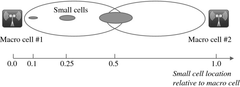
Figure 7.3 Small cell coverage area as a function of location

Figure 7.4 Small cell located close to macro cell #1 (Case 1)
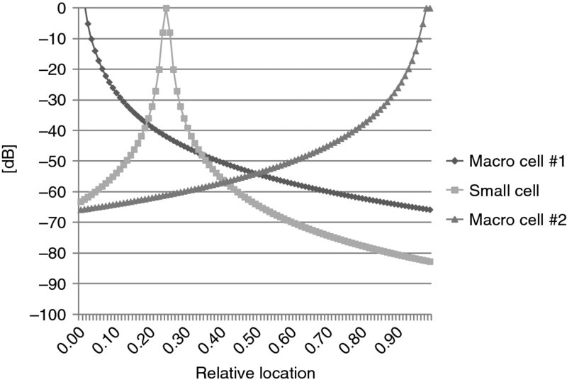
Figure 7.5 Small cell located between macro base station and cell edge (Case 2)
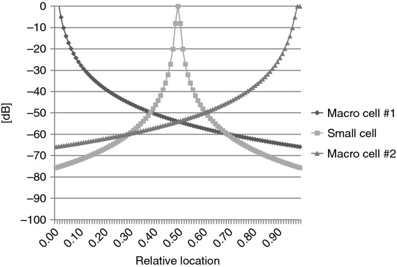
Figure 7.6 Small cell located at the edge of macro cell (Case 3)
The small cell range can be estimated based on the macro cell signal level. We assumed that the small cell transmission power, including the antenna gain, is 42 dBm and the path loss 140 dB + 40*log10(distance[km]). The result is shown in Figure 7.7. If the macro cell signal level is good, the small cell range remains very short. If the macro Received Signal Code Power (RSCP) is -50 dBm, the small cell range is just 35 meters. The small cell must be very close to the traffic source to provide offloading benefits. If the macro RSCP is -90 dBm, the small cell range becomes 350 meters, which allows the small cell to collect traffic from larger area.
7.5 HetNet Uplink–Downlink Imbalance
Another challenge with co-channel small cells is the link imbalance between macro and small cells. Since the small cell transmission power is lower than in macro cells, the UE can get closer to the small cell before the small cell moves into the active set. Therefore, the UE may cause higher uplink interference to the small cell before the small cell is able to power control the UE. In other words, the optimal handover locations are different in uplink and in downlink. The uplink handover location should be between macro and small cells where the path loss equalizes to both cells assuming the same base station uplink sensitivity. But the downlink handover location should be closer to the small cell due to lower small cell power. A number of options can be utilized to balance the uplink and downlink connections. One simple option is to desensitize the small cell uplink, which makes the small cell able to tolerate more interference. The desensitization is taken into account in 3GPP base station categories: the micro base station required sensitivity is 10 dB more relaxed compared to the macro base station case. That balances the uplink and downlink handover area. The link imbalance and the desensitization are shown in Figure 7.8. We assume macro cell transmission power of 40 W and small cell 6 W. The upper case assumes the same base station sensitivity of -121 dBm according to 3GPP while the lower plot assumes relaxed sensitivity of -111 dBm for the small cell.
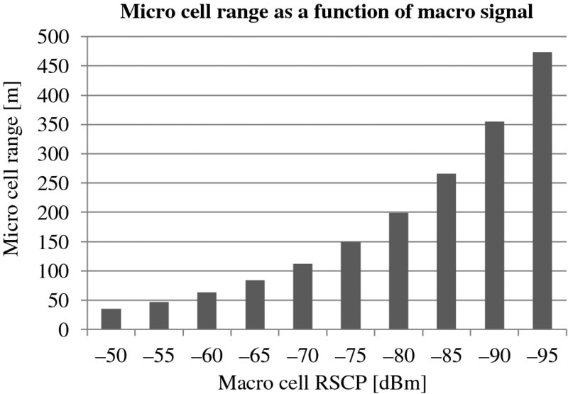
Figure 7.7 Co-channel micro cell range as a function of macro cell signal level

Figure 7.8 Balancing uplink and downlink cell borders
Desensitization is not an ideal solution since it increases unnecessarily the UE transmission power when connected to the small cells. Another solution is to use Cell Individual Offset (CIO) for the handovers which expands the small cell coverage area. The maximum value for CIO is normally 3 dB. If a larger CIO value is used, the downlink signal quality from the small cell tends to become too weak.
The area of potential interference issues is shown in Figure 7.9. When UE is in the soft handover area, UE power is controlled by both cells and there are no uplink interference issues. When UE is outside the soft handover area, UE may cause interference to the small cell. The gray color in Figure 7.9 indicates the area where UE can cause uplink interference to the small cell because it is not in soft handover and is not power controlled by the small cell. This area can be quite significant and reach up to 14% of the total area of a HetNet network layout assuming no desensitization and a small cell power of 1 W. The shape of the interference area largely depends on the location of the small cell towards the macro cell and on the small cell power. The higher the small cell output power, the smaller is the imbalance zone. This is straightforward, as the higher the power the more similar small cells become to a macro cells and hence the imbalance problem is reduced. The area of uplink interference is reduced in Figure 7.10 by using desensitization. This and other issues and solutions related to UMTS HetNet have been studied in 3GPP document [1].
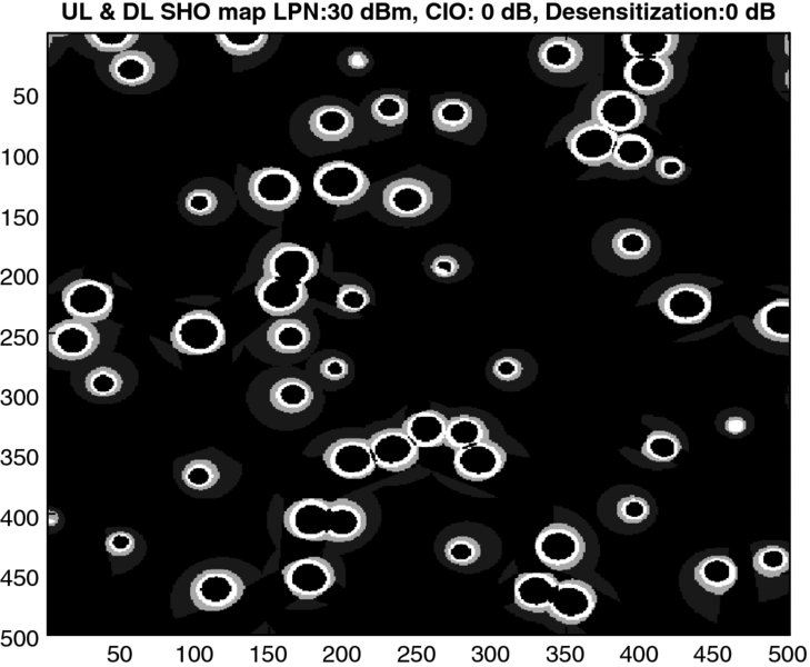
Figure 7.9 Areas of uplink interference without desensitization
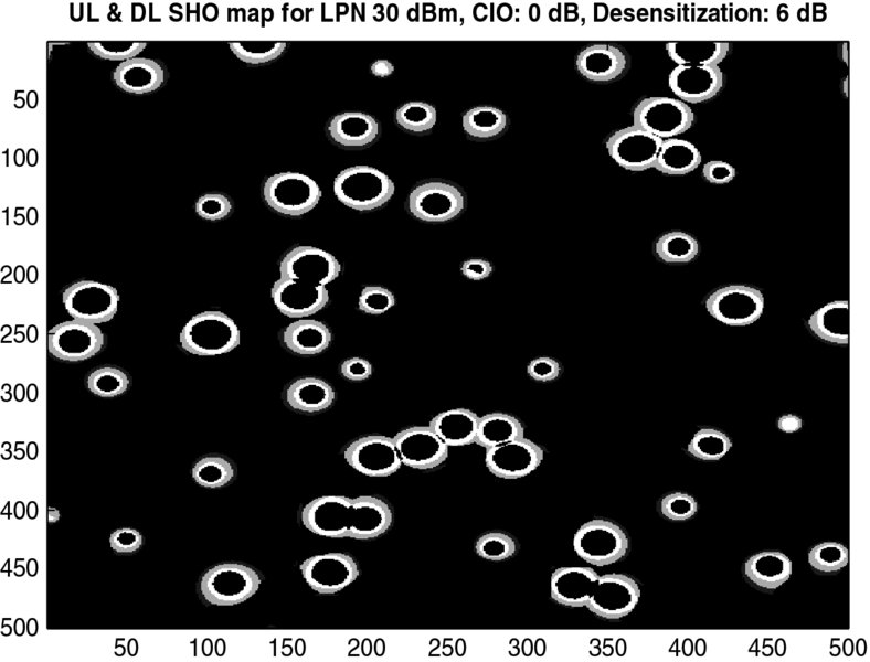
Figure 7.10 Areas of uplink interference with desensitization
7.6 HetNet Capacity and Data Rates
HetNet capacity and data rate gain in system simulations are presented in this section. The simulations assume macro cell transmission power of 20 W with antenna gain of 14 dBi and small cell power of 0.25 to 5 W with antenna gain of 5 dBi. The macro base station uses three sectors while the small cell has omni transmission. The number of small cells is two or four for every macro cell, which makes 6 to 12 times more small base stations than macro base stations. The Cell Individual Offset (CIO) has been 0 dB or 3 dB. The macro cell inter-site distance was 500 meters. The small cells were randomly placed in the macro cell areas.
The user locations in HetNet simulations have a major impact on the benefit of the small cells. If the users are randomly located in the macro cell area, the small cells can only provide marginal benefit because most users cannot be connected to small cells. In practice, operators place the small cells in the areas with highest user density. The assumption in these simulations is that 50% of users are placed close to the small cells within 20–60 meters depending on small cell power. The other 50% of users are placed randomly in the macro cell coverage area. An example placement of the small cells and UEs is show in Figure 7.11. The simulations assume a total of 16 UEs per macro cell.
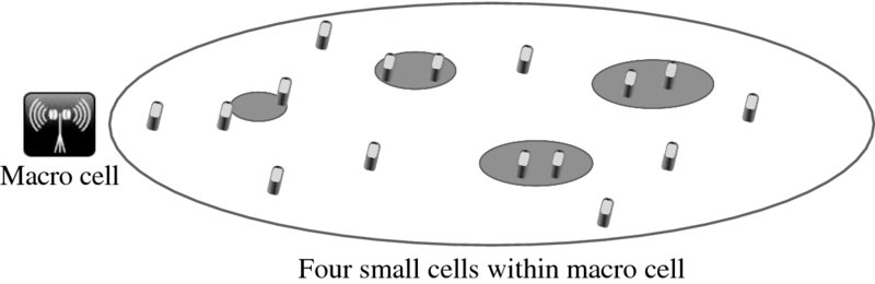
Figure 7.11 User locations in HetNet simulations
The first set of simulations assume a full buffer traffic model. The average and the cell edge user data rates are shown in Figure 7.12 and the gains compared to the macro only case in Figure 7.13. The user data rates are relatively low because of the high number of simultaneous full buffer users. The average data rate with the macro only case is 300 kbps and the cell edge 100 kbps. Both data rates are increased considerably by the introduction of small cells. The average data rate increases by 100–150% with two small cells and 150–250% with four small cells and reaching up to 1 Mbps. The cell edge data rates increase by 50–100% with small cells. The average data rate gain from two small cells is 125% and cell edge gain 70%. The corresponding gains with four cells are 185 and 85%. The simulations also show that the gain from 3-dB CIO is 15–25%.
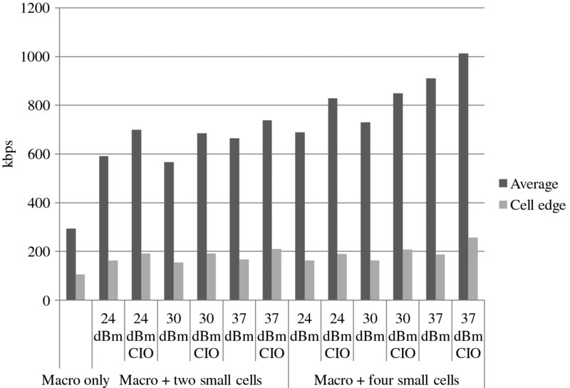
Figure 7.12 User data rates with full buffer
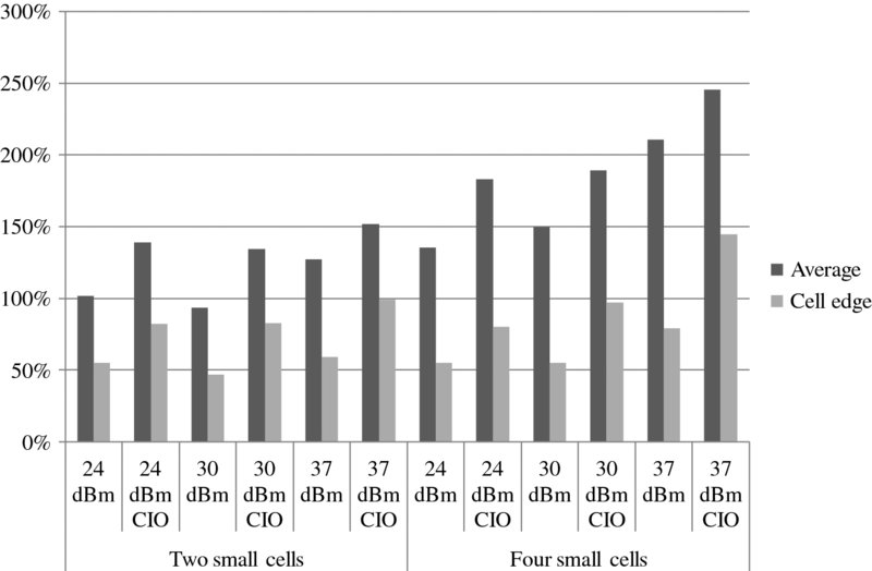
Figure 7.13 Gains compared to macro only case with full buffer
The network capacity gain with small cells is shown in Figure 7.14. Only one number for the capacity is shown for the different cases since the capacity was very similar with different small cell configurations with a given small cell density. The system throughput was 6 Mbps without small cells, 18 Mbps with two small cells, and even 27 Mbps with four small cells. It is interesting to note that the capacity provided by the small cells is approximately the same as the capacity of the macro cell, that is 6 Mbps per cell.
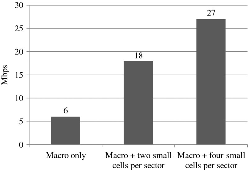
Figure 7.14 Network capacity with small cells
In order to study the improvements introduced by HetNet in terms of user experience, it is important to analyze the relation between the user burst rate and the offered load per sector in the system. Figure 7.15 shows the average user and cell edge (5th percentile) user burst rate versus offered load for macro only and HetNet scenarios. We assume four small cells with output power of 37 dBm, CIO, and 16 UEs per macro sector area. The gain introduced by HetNet can be interpreted in different ways. One can look at a constant user experience, for instance 7 Mbps, and see that the offered load can be increased by a factor of 3 or one can see the gain in the user throughput at a given load: a factor of 4.5 for 4.8 Mbps/sector load.
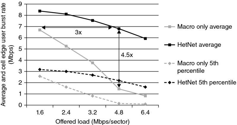
Figure 7.15 User data rates as a function of offered load per sector
The HSDPA Multiflow (see Chapter 5) [2] is characterized by simultaneous data transmission from two neighboring cells to a UE located at the border of those cells. The Multiflow solution can improve the cell edge data rates and balance the loading between adjacent cells, and that improvement is especially true for the HetNet scenarios.
In inter-site Multiflow the original data stream is split at the Radio Network Controller (RNC) and sent to each base station participating in the Multiflow transmission. Multiflow could be compared to a soft handover in Release 99: the UE must have a cell in its active set to establish Multiflow, and also in Release 99 soft handover two cells transmit to the UE. However, unlike soft handover the Multiflow data streams are different from each other, and are scheduled independently by the base stations and not by the RNC. Further, there is no automatic establishment of a Multiflow connection when a cell is taken into the active set. Instead, the usage of Multiflow transmission is determined for every UE by the RNC, and typically will not only depend on the SINR difference between the cells in the active set but also on the cell loads and UE traffic type.
There are two main reasons behind the development of Multiflow. Firstly, the problem with the reception quality at cell edge when the UE is far from the transmitter. In addition, cell edge UEs experience stronger interference from neighboring base stations. Secondly, the possibility of using transmissions from several cells provides a load balancing function where UE can utilize the resources from less loaded base stations. The load balancing is especially interesting in HetNet scenarios where an offloading of UEs to small cells is desired, but at the same time due to the smaller size of the cells more frequent handovers can be expected. With Multiflow, a higher level of robustness and smoother transitions between cells can be accomplished.
Simulation results with a bursty traffic model and HSDPA Multiflow are considered in Figure 7.16. The average file size is 750 kbits, inter-burst arrival time 5, and 16 UEs per macro cell, which makes the offered load 2.4 Mbps per sector. That leads to a loaded macro that still operates under a stable regime, that is, the offered load per UE is lower than the UE burst rate. The feedback channel for Multiflow operation was assumed to be ideal, assuming HS-DPCCH boosting can overcome UL/DL imbalances. The gains are expressed over the macro only case, with Multiflow contributing to improve the cell edge experience and HetNet pushing both the average and cell edge burst rates. Multiflow on top of HetNet provides extra gain in the cell edge, leading to 110% gain for a cell edge user burst rate over that which could be achieved by a user in the macro only scenario.
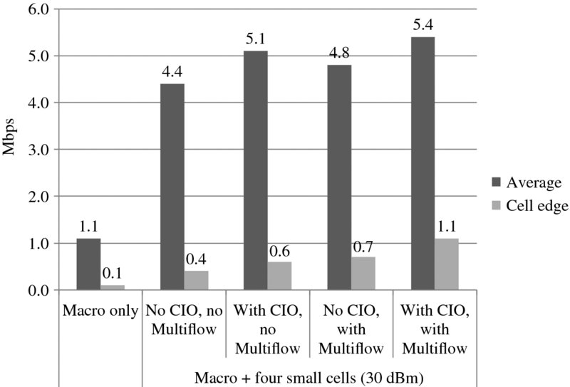
Figure 7.16 Downlink user burst rate gains introduced by HetNet and Multiflow
7.7 HetNet Field Measurements
This section presents a summary of small cell deployment in a large European city. The analysis focuses in more detail on the impact of two small cells: one deployed for coverage and another one deployed for capacity. The impact of small cell output power and small cell frequency usage is studied. The small cell is deployed with two different approaches: on the shared frequency with the macro cells and on the dedicated small cell frequency. The two small cell locations are illustrated in Figure 7.17.
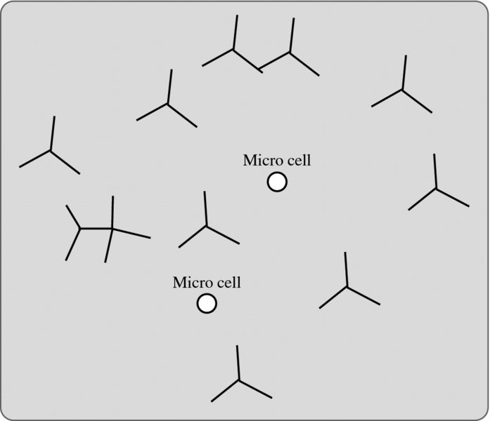
Figure 7.17 Two small cells (=circles) in the middle of three-sector macro cells
The traffic collected by the small cells was compared to the traffic collected by the adjacent macro cells in Figure 7.18. We can notice that the small cell collects more traffic when the small cell power is increased and when a dedicated small cell frequency is used. That behavior is expected since the small cell coverage area increases with higher power and with dedicated frequency. Also, the coverage driven small cell collects relatively high traffic when the surrounding macro signal is low. In the most extreme case the small cell collects even more traffic than the surrounding macro cells.
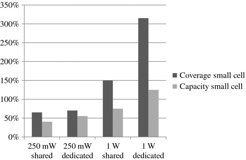
Figure 7.18 Relative traffic collected by small cells compared to adjacent macro cells
The user throughputs in the small cells are shown in Figure 7.19. The throughputs are between 1 and 2 Mbps in all cases. These results show that the throughputs are also satisfactory in the case of shared frequency and with different power levels. The higher power small cells collect more traffic but the user throughputs remain still at a good level. We need to note that HSPA+ features were not enabled during the trial and the backhaul was limited to 8 Mbps in Digital Subscriber Line (DSL), which reduced the throughputs.
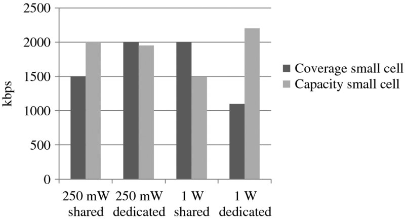
Figure 7.19 User throughputs in small cells
The small cell deployment showed that the small cells transfer a significant amount of data traffic and fulfill their offloading potential. The small cell can be deployed on the shared carrier with the macro cell. High power of 1 W, or even more, is beneficial to collect more traffic to the small cell.
7.8 Femto Cells
Femto cells refer to low power home or office base stations. Femto cells are connected to the operator's network via the person's own fixed broadband line. The main use case for femto cells is to improve the indoor coverage for smartphones. Femto cells are designed for low cost implementation and for simple installation which makes it possible for any user to connect a femto cell to his DSL modem. Femto cells can be given by the operator to the user as part of the contract to improve the coverage and to minimize the churn. Femto cells could also be paid for by the customers. The number of femto cells can be substantially more than the number of outdoor macro cells. There are operators that have ten times more femto cells than macro base stations. Therefore, femto cells are not directly connected to the core network but there is a femto gateway between. The femto gateway hides the large number of femto cells from the core network. The interface between the femto gateway and the core network is a normal Iu interface. The interface between femto cell and femto gateway is called Iuh. There is no RNC in femto architecture since RNC functionalities are embedded into femto cells. The femto architecture is shown in Figure 7.20.

Figure 7.20 Femto architecture
Femto cells use the operator's licensed frequencies. Femto cell frequency can be the same as macro cell frequency (co-channel) or a dedicated frequency. If operators are running out of capacity, then there is likely no dedicated frequency available for femto cells. Femto cells can be deployed on the same frequency as macro cells if femto cells are mainly targeted to improve indoor coverage in those areas with a weak macro signal. If the macro signal is strong, it will be beneficial to use a dedicated frequency for femto cells to avoid interference between macro and femto cells and to offer higher data rates with femto cells. The interference management between macro and co-channel femto cells can be obtained by a power control solution where the femto cell first measures the macro cell signal level and then sets femto cell transmission power accordingly. The interference between femto cells may also impact the user data rates in the case of dense femto deployment in apartment buildings.
Femto cells can be defined for Closed Subscriber Groups (CSGs) or for open access. The owner of a home femto cell can define the list of users who are able to access the femto cell. That feature allows the home owners to control who is able to use femto cell and DSL connection. The CSG control for pre-Release 8 UEs is located in the femto gateway. The CSG control for Release 8 UEs is located in the core network based on the information provided by the UE.
Femto cells support a listening mode which refers to the downlink receiver in the femto cell. The listening mode allows identification of those macro cells and femto cells that can be received in the area. The downlink receiver also allows measurement of the macro cell signal level which can be used when setting femto cell transmission power. Femto cells are identified by dedicated scrambling codes. Typically, a few scrambling codes are dedicated to femto cells. These scrambling codes can be indicated by all the macro cells in the area.
The mobility between macro and femto cells needs to be considered in order to provide a seamless end-user experience. The outgoing handovers from femto to macro were supported already in the first femto cells and by legacy UEs. The outgoing handover is important to maintain the ongoing call when leaving the femto cell coverage area. The incoming handover is supported in Release 9, while reselection from macro to femto is used in pre-Release 9 UEs. If there is an ongoing call in pre-Release 9 UE when entering femto cell coverage area, the call remains in the macro cell. When the call is over, the UE moves to femto cells by itself with reselection. The further mobility improvements between macro and femto, and between two femto cells, are included in Releases 10 and 11 which eventually allow soft handover for the mobility cases. It is also possible to support handover from macro to femto, and between two femtos, for the legacy Release 8 UEs in the case of coordinated femto deployment. The coordinated case refers to open access hot spots and enterprise femtos where the deployment is planned in terms of scrambling codes and the femto cells are listed in the neighborlist in the macro cell. The handover can be intra-frequency or inter-frequency. The femto mobility features for uncoordinated deployment are shown in Figure 7.21.
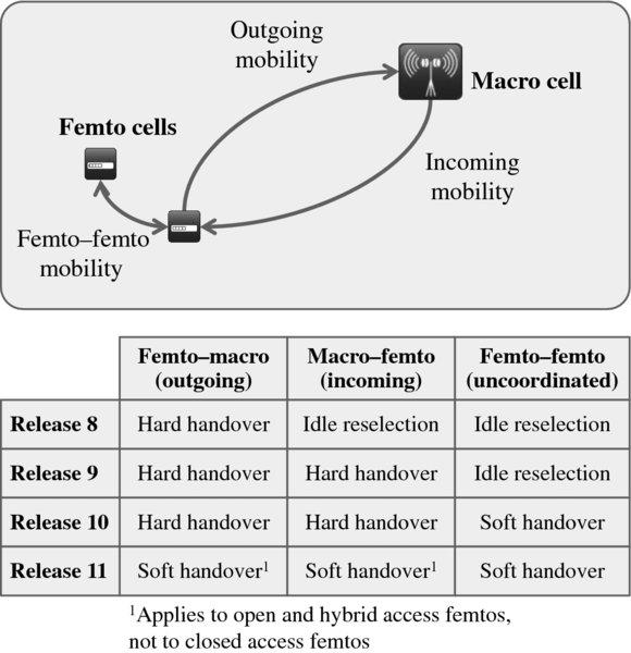
Figure 7.21 Femto mobility solutions for uncoordinated deployment
Most of the femto units in commercial networks are used for residential indoor coverage. Residential femtos need to support just a small number of users and there is no need for handovers between two femtos. The femto solution is also used for enterprise coverage. The enterprise solution sets higher requirements for the femto access points: higher user capacity and inter-femto mobility features are required.
Commercial femto deployments began during 2009 mainly as a fill-in solution for improving home coverage. In the long term, femto cells could also be used to off-load high traffic from the macro network. Femto cells also change the operator's business assumptions because the access point is purchased and installed by the end user and the transmission and the electricity is paid by the end user.
Practical deployments have shown that the following areas need to be considered in femto deployments:
- – The supported features may be different in femto and macro cells. Typically, femto cells did not support all the same features as macro cells because different hardware and software platforms were used in femto and macro cells.
- – The data rates in femto cells may be limited by the DSL backhaul. Many DSL lines are limited to 8–10 Mbps data rates that are lower than the HSDPA peak rates of 21 Mbps and 42 Mbps. It may be that the macro cells can provide even higher data rates than femto cells.
- – Soft handovers are typically not available between co-channel femto and macro cells. The lack of soft handovers impacts the reliability of the mobility.
- – A dedicated frequency for femto cells eats part of macro capacity and it is increasingly difficult to allocate a dedicated femto frequency when the macro cell traffic increases.
- – If a dedicated femto frequency is utilized, then CSFB with LTE phones gets more complex. The CSFB target need to be decided based on UE measurements between macro and femto frequency.
- – Different location areas are used in macro and femto cells. The UE performs a location area update whenever moving between the layers. Attention is required to make sure that paging messages are not lost during the change of location area.
- – The maximum number of users is typically limited in femto cells, which may cause problems if using femto cells in large enterprises or in public premises.
- – The femto and macro cells are typically provided by different vendors and the corresponding operability tools are also different.
- – The femto cell adds co-channel interference which may impact those UEs that are in weak macro signal and are not able to connect to CSG femto cells.
Field experiences have shown that the femto solution works fine for enhancing indoor coverage at homes or in small enterprises, while it is not practical to deploy femto solutions outdoors and in public premises. The outdoor solution needs a Iub/RNC connection for smooth mobility and interference control, more transmission power, higher capacity, and feature parity with macro cells.
7.9 WLAN Interworking
WLAN (Wi-Fi) can complement mobile networks in carrying part of the data traffic and reducing the mobile network loading. In practice, all medium and high category mobile devices have Wi-Fi radio, which enables efficient offloading of data traffic to Wi-Fi. Most users can configure the mobile device to use Wi-Fi at home and in the office but it tends to be more complex to utilize public Wi-Fi networks. Mobile operators may also want to control which Wi-Fi networks are utilized in order to guarantee adequate performance and costs related especially to roaming hotspots. Two mainstream solutions are Access Network Discovery and Selection Function (ANDSF) and Hotspot 2.0. ANDSF is standardized by 3GPP while Hotspot 2.0 is defined by Wi-Fi Alliance with IEEE specifications. Both solutions are described in this section.
7.9.1 Access Network Discovery and Selection Function (ANDSF)
ANDSF based selection between Wi-Fi and mobile networks follows the same logic as Visited PLMN (VPLMN) selection in the case of mobile roaming. Most users are happy with automatic roaming network selection based on the operator priorities in the (U)SIM card. The UE uses the highest priority network out of the currently available networks. But the user is still able to override the automatic selection and select another mobile network.
3GPP has standardized ANDSF interfaces. The first version of ANDSF was included into 3GPP Release 8 and was enhanced in later releases. The interfaces allow an operator to give Wi-Fi network selection policies to the terminals and define when and where to use 3GPP and Wi-Fi networks. ANDSF architecture is shown in Figure 7.22. The ANDSF server provides the priority information to the UE over the S14 interface. The S14 interface is defined based on the Open Mobile Alliance (OMA) Device Management (DM) framework. The messages are transferred on top of IP. In order to contact the ANDSF server, the UE needs an active data connection to the network. The most relevant 3GPP references are [3–5].
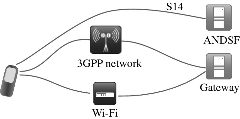
Figure 7.22 ANDSF architecture
ANDSF can provide three kinds of information:
- Inter-System Mobility Policy (ISMP) is the original network selection policy defined in Release 8. The same network policy information is used for all the applications in the UE. It is possible to prioritize WLAN networks based on the Service Set Identifier (SSID). An example ISMP policy:
- Priority 1: use WLAN with SSID "Operator own network."
- Priority 2: use WLAN with SSID "Roaming partner network,"
- Priority 3: use 3GPP radio access.
- Access Network Discovery Information: the main use is to facilitate the terminal's network discovery process to allow the terminal to learn approved Wi-Fi networks and to avoid unnecessary scanning. By using validity conditions a UE can utilize, for example, associated location information to optimize Wi-Fi scanning process and thus save battery.
- Inter-System Routing Policy (ISRP): ISRP policies were added into ANDSF in Release 10. The idea is that it is possible to identify different applications and define separate network policies for each application. For example, QoS aware applications may use only 3GPP or proven quality Wi-Fi networks.
ANDSF also offers the following flexibility:
- – The ANDSF priority information can depend on the time of the day and on the location: offloading to Wi-Fi can be used in high traffic areas like stadiums or during the mobile network's busy hours.
- – The ANDSF policy can also be given to the roaming users in addition to the operator's own subscribers. The roaming case covers both own subscribers roaming in another network and other network subscribers roaming in this network.
- – The initiation of the ANDSF session establishment is done by the UE. The session initiation trigger can be based on expired ANDSF policy information, UE configuration, or some other implementation dependant trigger. Also, the ANDSF server may trigger UE to initiate the session establishment. These two cases are called pull mode and push mode.
7.9.2 Hotspot 2.0
Hotspot 2.0 is defined by the Wi-Fi alliance and leverages the IEEE 802.11u standard which enables cellular-like roaming. Hotspot 2.0 is focused on enabling a mobile device to automatically discover those access points that have a roaming arrangement with the user's home network and then securely connect. Hotspot 2.0 is also known as Wi-Fi certified passpoint. The device can retrieve information on the access points before associating with an access point and then select the most suitable access point based on this info. The Hotspot 2.0 Release 1 specification has been completed and certified in 2013, see [6], while Release 2 is expected during 2014 [7]. A general description of Hotspot 2.0 is shown in [8].
The key protocols within 802.11u are Generic Advertisement Service (GAS) and Access Network Query Protocol (ANQP). ANQP is a query and response protocol used between the Wi-Fi network and the mobile device to discover information such as the network authentication types supported, venue name, roaming agreements in place, load, throughput of the backhaul link, and other information useful in the network selection process. ANQP messages are transferred over GAS. The Hotspot 2.0 protocols are shown in Figure 7.23. When a user with a Hotspot 2.0-capable mobile device comes within a range of a Hotspot 2.0-capable access point, it will automatically open up a dialog with that access point to determine its capabilities. This is done using ANQP packets, which allow the device to learn the capabilities of the access point. At this point, the device has not yet attached to the access point and does not yet have an IP address. The selection process can be influenced both by user preference and operator policy. Automating this manual configuration and decision-making process makes Wi-Fi usage simpler, and increases the use of Wi-Fi services. Another benefit is that Hotspot 2.0 recommends use of Wi-Fi Protected Access (WPA2) enterprise security, which harmonizes the technology landscape and leads to wider UE support of secure communication.
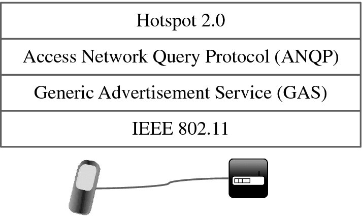
Figure 7.23 Hotspot 2.0 protocols
In short, Hotspot 2.0 works in practice as follows:
- 802.11u-capable access point indicates Hotspot 2.0 support.
- Device selects access point.
- Device runs Access Network Query Protocol (ANQP) request.
- Access point responds with requested information.
- Device compares profile information against Hotspot 2.0 data from APs and selects the most suitable network.
7.9.3 Differences between ANDSF and Hotspot 2.0
The main differences between ANDSF and Hotspot 2.0 are listed in Table 7.2. ANDSF is defined by 3GPP and the Wi-Fi information is provided via any network, while Hotspot 2.0 gives the information via the Wi-Fi network. ANDSF allows prioritization between 3GPP and the Wi-Fi network which is not supported in Hotspot 2.0. On the other hand, Hotspot 2.0 gives information about the quality of Wi-Fi networks which is not available in ANDSF. In short: ANDSF and Hotspot 2.0 are complementary solutions. ANDSF provides mobile network operator tools to tell UE when and where to use 3GPP or Wi-Fi networks according to operator business policies, for example, use roaming partner hotspot adding operator costs only during football games or in subway stations. Hotspot 2.0 enables UE to select the best Wi-Fi access point among multiple candidates. Hotspot 2.0 is also applicable for tablets without a SIM card.
Table 7.2 Differences between ANDSF and Hotspot 2.0
| ANDSF | Hotspot 2.0 | |
| Standardization | 3GPP | IEEE 802.11 and Wi-Fi Alliance |
| Information available | Via cellular and Wi-Fi. UE can reach ANDSF server via any access | Via Wi-Fi |
| Prioritization between 3GPP and Wi-Fi | Yes, information on when and where to select 3GPP or Wi-Fi | Only Wi-Fi selection |
| Prioritization of Wi-Fi networks | Yes, different Wi-Fi networks can be prioritized | Own Wi-Fi can be prioritized but other Wi-Fi networks have the same priority |
| UE location information | Yes | No |
| Roaming support | Yes | Yes |
| Type of access network | No | Yes: public, private, with guest access, chargeable public, free public, etc. |
| Venue | No | Yes, group (residential, business), type, name etc. |
| Wi-Fi access point performance information | No | Yes. UE can avoid congested access points |
| Network authentication type | No | Yes |
3GPP brings enhanced HSPA/LTE and Wi-Fi interworking in Release 12. See Chapter 16 for a summary.
7.10 Summary
Small cell deployments are driven by the need for enhanced capacity and improved coverage. Current technology enables implementation of compact small cell products, which makes the practical small cell deployment easier than ever before. Since operators tend to use all their frequencies in macro cells, there will be no dedicated frequencies available for small cells but instead small cells need to share the frequency with macro cells. Co-channel deployment creates some challenges, including the dominance areas and uplink–downlink balancing. The simulations show that small cell deployments can boost data rates considerably. Optimized small cell rollout with four micro cells per macro sector can increase user data rates by a factor of 3.5x. Field measurements have also confirmed small cell benefits. Femto cells have been successfully used for enhancing indoor coverage at homes and in small enterprises but femto cells are not suitable for outdoor deployment. Mobile operators can complement their cellular networks by offloading data traffic to Wi-Fi. ANDSF and Hotspot 2.0 solutions provide the means for operators to control traffic offloading.
References
- 3GPP Technical Report 25.800 “UMTS Heterogeneous Networks”, v.12.0.0, 2013.
- 3GPP Technical Specification 25.308 “High Speed Downlink Packet Access; Overall Description; Stage 2 (Rel 11)”, v.11.6.0, 2013.
- 3GPP Technical Specification 23.402 “Architecture enhancements for non-3GPP accesses”, v.11.7.0, 2013.
- 3GPP Technical Specification 24.312 “Access Network Discovery and Selection Function (ANDSF) Management Object (MO)”, v.11.6.0, 2013.
- 3GPP Technical Specification 24.302 “Access to the 3GPP Evolved Packet Core (EPC) via non-3GPP access networks; Stage 3”, v.11.7.0, 2013.
- Wi-Fi Alliance Hotspot 2.0 Certified Passpoint Release 1, 2013.
- Wi-Fi Alliance Hotspot 2.0 Release 2, 2014.
- “Hotspot 2.0 – Making Wi-Fi as easy to use and secure as cellular”, White paper, Ruckus Wireless, 2013.