
9
IMT-Advanced Performance Evaluation
Karri Ranta-aho and Antti Toskala
9.1 Introduction
This chapter presents a performance evaluation of HSPA Release 11 compared to the requirements for IMT-Advanced as defined by the ITU-R. First the IMT-Advanced requirements are presented and then the different features included in Release 11 3GPP specifications to address these requirements are briefly introduced to highlight how they help in achieving the improved performance. The achievable performance with different features is covered. This chapter is concluded by benchmarking with the LTE and LTE-Advanced.
9.2 ITU-R Requirements for IMT-Advanced
The International Telegraphic Union Radiocommunications sector (ITU-R) [1] started the process for the new system, the International Mobile Telecommunications Advanced (IMT-Advanced), with a circular letter distributed in 2008. The circular letter was a call for radio technology proposals, in a similar fashion as had been done earlier for the IMT-2000 process in connection with the definition of 3G radio access solutions [2]. Now the ITU-R was calling for proposals for radio technologies that could meet the requirements set for IMT-Advanced technology, widely termed the 4th generation (4G) mobile communication systems.
The ITU-R defined the requirements for the IMT-Advanced (4G) such that the system should be able to achieve the following [3]:
- Enable 100 Mbps peak data rate support for high mobility and up to 1 Gbps peak data rate for the low mobility case.
- Allow inter-working with other radio access systems.
- Enable high quality mobile services.
- Capable of worldwide roaming.
- Flexibility to allow cost efficient support of a wide range of services and applications.
- Bandwidth scalability up to and including 40 MHz, with considerations up to 100 MHz.
Furthermore, there were more detailed performance requirements in the following areas:
- Peak spectral efficiency in downlink and uplink.
- Cell spectral efficiency, ranging from 3 bits/s/Hz/cell in the indoor downlink scenario, to 0.7 bits/s/Hz/cell in the 120 km/h rural uplink scenario.
- Cell edge user spectral efficiency, ranging from 0.1 bits/s/Hz/user in the indoor downlink scenario, to 0.015 bits/s/Hz/user in the 120 km/h rural uplink scenario.
- Mobility support with up to 350 km/h (smaller data rate allowed compared to the stationary use case).
- Latency requirements for the control plane to achieve 100 ms transition time between idle and active state, and respectively to enable 10 ms user plane latency (in unloaded conditions).
- Handover interruption of 27.5 ms for the intra-frequency case and 40 and 60 ms for the inter-frequency within the band and between the bands respectively.
- VoIP capacity, with the numbers of users ranging from 30 to 50 users per sector/MHz.
The requirements related to items such as peak spectral efficiency requirements or functional requirements such as achievable latency or handover interruption time can be investigated relatively easy, while the requirements related to the average and cell edge spectral efficiency, with examples shown in Table 9.1, typically need detailed system-level studies with simulations.
Table 9.1 Summary of key ITU-R IMT-A requirements
| System performance requirements | ITU-R requirement |
| Downlink peak spectrum efficiency | 15 bits/s/Hz (max 4 antennas) |
| Uplink peak spectrum efficiency | 6.75 bits/s/Hz (max 2 TX antennas) |
| Downlink average cell spectral efficiency | ≥1.1…3.0 bits/s/Hz |
| Uplink average cell user spectral efficiency | ≥0.7…2.25 bits/s/Hz |
| Downlink cell edge user spectral efficiency | ≥0.04…0.1 bits/s/Hz |
| Uplink cell edge user spectral efficiency | ≥0.015…0.07 bits/s/Hz |
| User plane latency | ≤10 ms |
| Control plane latency | ≤100 ms |
| Handover interruption | ≤27.5…60 ms |
It was rather obvious that new features were needed on top of Release 10 HSPA in order to meet some of these requirements with HSPA technology. As shown in the following chapters, the requirements for dealing with items such as handover delay or control plane latency were already at such a level with HSPA that fundamental changes to the control plane operation in order to meet IMT-Advanced requirements could be avoided.
9.3 3GPP Features to Consider in Meeting the IMT-Advanced Requirements
While LTE-Advanced was developed during Release 10 and submitted to the IMT-Advanced process, no such activity took place for HSPA in Release 10. It was only in the next 3GPP Release, Release 11, that the following key items were studied and specified for HSPA in order to meet the ITU-R requirements defined for IMT-Advanced:
- Eight-carrier aggregation, aggregating up to eight 5-MHz carriers together, thus giving up to eight times faster data speeds compared to single-carrier operation, as covered in Chapter 3.
- Four-transmit and four-receiver antenna (4 × 4) Multiple Input Multiple Output (MIMO) in the downlink direction, roughly doubling peak data rates and system capacity for devices with four receiver antennas compared to devices with two receiver antennas, as covered in Chapter 3, enabling to meet the requirements in Table 9.2.
- Uplink beamforming, 2 × 2 MIMO and 64QAM. Uplink improvements which increase the peak data rate, user performance, and cell capacity, as discussed in Chapter 3.
- HSDPA Multiflow – increases downlink user throughputs at the cell edge, as covered in Chapter 5.
These features contribute to the HSPA peak data rate evolution from 3GPP Release 5 onwards, as shown in Figures 9.1 and 9.2. The features contributing to peak data rates are shown in Table 9.3. In the downlink direction it is possible to exceed 300 Mbps with the use of either 20 MHz of spectrum and four-transmit and four-receive antenna MIMO operation or using 40 MHz of spectrum (with eight-carrier aggregation) and two-antenna MIMO operation. In the uplink, respectively, the use of 64QAM and uplink two-antenna MIMO transmission could increase the peak data rate for 70 Mbps when aggregating two uplink carriers (dual-carrier HSUPA) but are not supported simultaneously in Release 11.
Table 9.2 Latency and handover interruption requirements
| IMT-A minimum | HSPA Release 10 | ||
| requirement | and prior | ||
| Downlink peak spectral efficiency | 15.0 bits/s/Hz | 8.6 bits/s/Hz | |
| Uplink peak spectral efficiency | 6.75 bits/s/Hz | 2.3 bits/s/Hz | |
| Bandwidth scalability | Scalable, up to | Scalable, up to | |
| 40 MHz | 20 MHz | ||
| Control plane latency | ≤ 100 ms | 75 ms | |
| User plane latency | ≤ 10 ms | 8 ms | |
| Handover interruption | Intra-frequency | ≤ 27.5 ms | 0 ms |
| Inter-frequency | ≤ 40 ms | 13 ms | |
| Inter-band | ≤ 60 ms | 13 ms | |
Table 9.3 HSPA peak rate feature evolution from 3GPP Release 5 to Release 11
| Downlink (HSDPA) features | Uplink (HSUPA) features | |
| Release 5 | HSDPA (single carrier, no MIMO, 16QAM) | |
| Release 6 | HSUPA (single carrier, no MIMO, QPSK) | |
| Release 7 | 2 × 2 MIMO (28 Mbps), 64QAM (21 Mbps) | 16QAM |
| Release 8 | 2 × 2 MIMO + 64QAM and dual carrier + 64QAM | |
| Release 9 | Dual carrier + 2 × 2 MIMO + 64QAM | Dual carrier + 16QAM |
| Release 10 | Four-carrier + 2 × 2 MIMO + 64QAM | |
| Release 11 | Eight-carrier + 2 × 2 MIMO + 64QAM and four-carrier + 4 × 4 MIMO + 64QAM | Dual carrier + 2 × 2 MIMO + 64QAM |
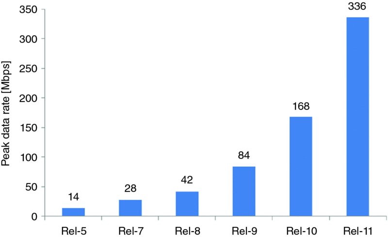
Figure 9.1 Downlink (HSDPA) peak rate evolution
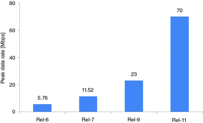
Figure 9.2 Uplink (HSUPA) peak rate evolution
When comparing the achievable peak spectrum efficiency values with IMT-Advanced requirements and improvements achieved in Release 11 HSPA, it can be noted that the IMT-Advanced requirements can be reached, as shown in Table 9.4, with the introduction of
- 4 × 4 MIMO for peak downlink spectral efficiency;
- 2 × 2 MIMO and 64QAM for peak uplink spectral efficiency;
- eight-carrier HSDPA for bandwidth.
Table 9.4 Peak spectral efficiency and bandwidth scalability requirements
| IMT-Advanced
minimum requirement |
HSPA Release 10 | HSPA Release 11 | |
| Peak spectral efficiency, downlink | 15.0 bits/s/Hz | 8.6 bits/s/Hz
(2 × 2 MIMO + 64QAM) |
17.2 bits/s/Hz
(4 × 4 MIMO) |
| Peak spectral efficiency, uplink | 6.75 bits/s/Hz | 2.3 bits/s/Hz
(16QAM) |
6.9 bits/s/Hz
(2 × 2 MIMO + 64QAM) |
| Spectrum flexibility | Scalable bandwidth, up to 40 MHz | Scalable up to 20 MHz
(four-carrier HSDPA) |
Scalable up to 40 MHz
(eight-carrier HSDPA) |
Note that Release 10 refers to the features included up to and including Release 10. The peak spectral efficiency values in Table 9.4 are based on simply calculating the maximum achievable peak data rate and dividing by the bandwidth required.
The Release 11 work was finalized in the first half of 2013.
How each of these features individually contribute to meeting the IMT-Advanced requirements on average and cell edge spectrum efficiency based on the simulations is studied in the following sections. The peak spectrum efficiency and other resulting improvements are also addressed.
9.4 Performance Evaluation
9.4.1 Eight-Carrier HSDPA
Release 8 Dual-Carrier HSDPA (DC-HSDPA) has been widely taken in to use in many HSDPA networks, and it provides data rates of up to 42 Mbps, as introduced in Chapter 3. In Release 9 the solution was extended to cover dual-carrier operation on two different frequency bands, while further carriers were added with up to four carriers in Release 10 and up to eight downlink carriers in Release 11.
The resulting peak data rate (with the use of a 40 MHz spectrum for eight carriers) reaches 336 Mbps with 2 × 2 MIMO. The same peak rate can also be reached with four carriers and 4 × 4 MIMO, but notably the specification does not support simultaneous operation of 4 × 4 MIMO and more than four carriers. Release 11 also enables aggregating non-adjacent carriers on the same frequency band.
Aggregating multiple carriers brings substantial benefits for the end user because any free resources across all carriers can be used flexibly. This provides a dynamic pool of resources, with the multicarrier capable devices able to use any of the carriers with 2 ms resolution, thus allowing an even load with the bursty traffic too, leading to high trunking gain with the dynamic packet sharing over a large number of carriers.
Unlike the single carrier device, the multicarrier capable device may be re-allocated to the carrier or carriers that are experiencing the best propagation and interference conditions every 2 ms, thus maximizing the resulting system throughput.
The gains can be seen in Figure 9.3, which shows the cumulative distribution of the average user throughput and the mean packet call delay for macro cells with an average cell load of 1 Mbps.
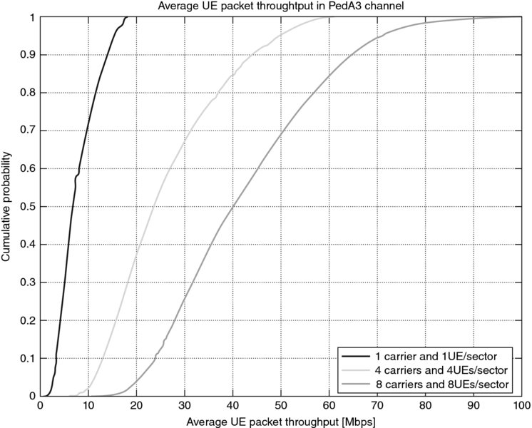
Figure 9.3 Cumulative distribution probability of the average device packet throughput for one, four, and eight carriers at low offered system load
The gains depend significantly on the load in the system. If the load is very high and there are a large number of users, then there will be fewer free resources on the other carriers and there is a high likelihood that there will be several users in a good propagation condition on each carrier, thus resulting in lower gains.
For meeting the requirements for the ITU-R IMT-Advanced system, the eight-carrier HSDPA allows aggregation of 40 MHz of spectrum, meeting the requirement for flexible system bandwidth support up to 40 MHz.
9.4.2 Four-Antenna MIMO for HSDPA
The MIMO solution with two transmit and two receiver (2 × 2) antennas was introduced in Release 7, as covered in Chapter 3. To further push the multiantenna transmission capability, MIMO operation with four transmit and four receiver antennas (4 × 4) was introduced. In 4 × 4 MIMO the NodeB uses four transmit antennas and the UE uses four receiving antennas forming four different reception images for each four transmitted signals between the transmitter and receiver, as shown in Figure 9.4. This enables transmission of up to four parallel streams, which doubles the peak data rate compared to 2 × 2 MIMO and also improves the typical cell capacity and user data rates directly benefiting from additional receive antennas, even if four-stream transmission is not possible due to less favorable radio conditions.
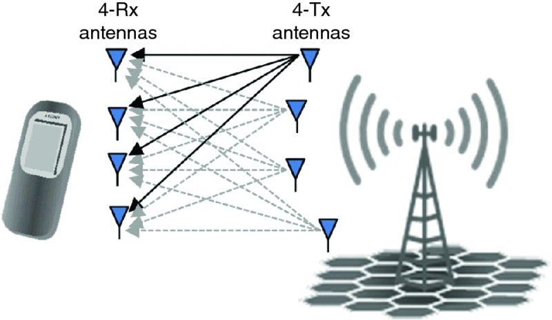
Figure 9.4 4 × 4 MIMO operation in downlink
This can be seen in Figure 9.5, showing the average macro cell throughput assuming an ideal channel. It can be seen that adding Rx antennas gives more benefits than adding Tx antennas, while the maximum gain is achieved by using four transmit and four receive antennas. In that case, the system will automatically switch between beamforming with four antennas and using the antennas to send up to four parallel streams based on the link quality.
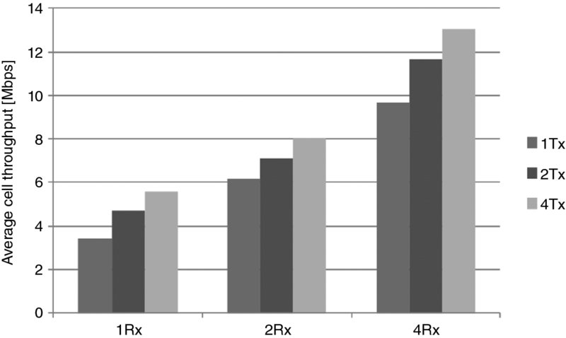
Figure 9.5 Average cell throughput with different numbers of Rx and Tx antennas
From the perspective of the ITU IMT-Advanced requirements, the 4 × 4 MIMO, when coupled with 64QAM modulation, reaches 17.2 bits/s/Hz peak spectral efficiency, exceeding the IMT-A minimum requirement of 15 bits/s/Hz.
9.4.3 Uplink Beamforming, MIMO and 64QAM
It was also important to improve the performance in the uplink direction, but adding a very large number of carriers was not desirable as that would have degraded the waveform properties and resulted in very difficult power amplifier requirements. Instead, improvements were made for the single carrier transmission (dual-carrier uplink had also been defined earlier) to reach the bits/s/Hz requirement. The following solutions were introduced:
- Uplink beamforming allows uplink dual-antenna transmission to provide better data rate coverage and lower interference from neighboring cells.
-
It will also double the peak uplink rate using dual-stream MIMO transmission and triple it when coupled with 64QAM modulation. Analogous to the downlink MIMO, the mobile device uses two transmit paths and antennas to form a complex radio wave pattern in the multiple base station receive antennas, as shown in Figures 9.6 and 9.7. In favorable radio conditions, this yields over 2 dB in the link budget, which translates into up to 30% higher average uplink data rates throughout the cell and up to 40% higher data rates at the cell edge. In another analogy to downlink MIMO, in very good channel conditions and when a high received signal-to-noise ratio is possible, the user equipment may use dual-stream MIMO transmission with two orthogonal beam patterns. This effectively doubles the raw bitrate on the physical layer.
- When further moving from 16QAM to 64QAM modulation, the raw bitrate is tripled together with 2 × 2 MIMO transmission when compared to single stream and 16QAM.
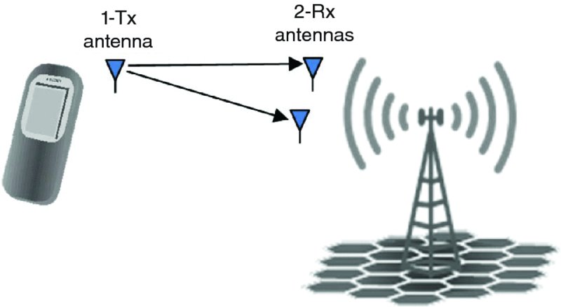
Figure 9.6 Single Tx antenna uplink
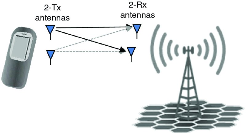
Figure 9.7 Dual Tx antenna uplink enabling beamforming transmit diversity and 2 × 2 MIMO
To achieve received signal-to-noise ratios that are high enough to make dual-stream transmission with 64QAM possible over a significantly large area, four or even eight receiver antennas, or a combination of both, may need to be deployed. Yet again this is analogous to what happens in the downlink.
Dual-antenna transmission in the uplink should be viewed as two separate features. First, there is uplink beamforming, which is possible and beneficial in most environments and which helps in the full cell area by providing better uplink data rate coverage. Second is the uplink dual stream MIMO, which is possible only in more limited scenarios and doubles the uplink peak rate.
Introducing 64QAM modulation does not require two transmit antennas, but when aiming for the highest peak rates, it needs to be coupled with uplink MIMO.
Figure 9.8 shows the gains of beamforming on the average and cell edge throughput. It can be seen that gains of up to 20 and 80% respectively can be achieved.
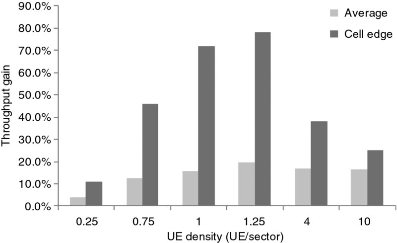
Figure 9.8 Average and cell edge (10%) gain from uplink beamforming in 2.8 km ISD network
From the perspective of the ITU IMT-Advanced requirements, uplink beamforming helps achieve the average and cell edge performance requirements. The uplink 2 × 2 MIMO, together with 64QAM modulation, achieves 6.9 bits/s/Hz peak spectral efficiency, exceeding the IMT-A minimum requirement of 6.75 bits/s/Hz.
9.4.4 HSPA+ Multiflow
Another feature enabling a better use of resources in cellular systems is HSPA+ Multiflow, which is designed to improve cell edge data rates. Multiflow, as covered in more detail in Chapter 5, enables the transmission of data from multiple cells to a user device at the common cell edge, instead of transmitting the data via a single cell as in HSDPA today. This is illustrated in Figures 9.9 and 9.10 for dual-cell Multiflow operation. With inter-BTS Multiflow the RNC splits the incoming data stream to two independent flows that are transmitted to the UE by two independent NodeBs on the same carrier frequency. With intra-site Multiflow the NodeB MAC layer splits the single data flow coming from the RNC just like in multicarrier HSDPA operation, but the transmission takes place over neighboring sectors of the NodeB on the same carrier frequency, as opposed to multicarrier operation where the data is transmitted on different carrier frequencies, but on the same sector.
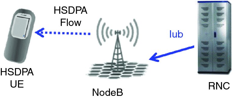
Figure 9.9 Conventional HSDPA
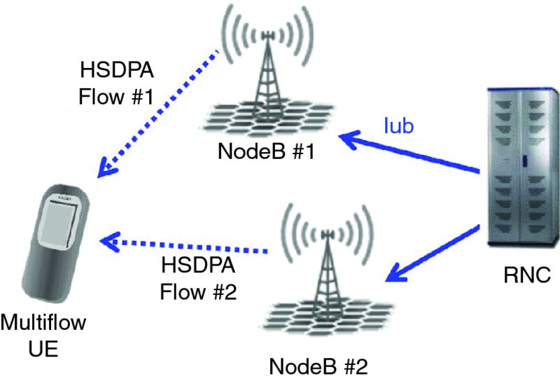
Figure 9.10 HSPA+ Multiflow
Each of the data flows in Multiflow can be scheduled independently, simplifying the concept and enabling simple inter-site deployment without the need for tight network synchronization. The presence of two HSDPA flows from two cells leads to a doubling of the power available for the desired signal at the device, which is used to increase the overall user throughput. For 3GPP Release 11, Multiflow is considered for up to four different flows over two different frequencies, enabling the radio network to send data from two different base stations and up to four different cells to a user device.
Figure 9.11 shows the cumulative distribution of the throughput experienced by the user with and without Multiflow (including both intra-site and inter-site Multiflow devices). At the low values of the cumulative distribution, users at the cell edge gain particular benefit from Multiflow, since they are the most likely to receive transmissions from multiple cells with adequate signal quality.
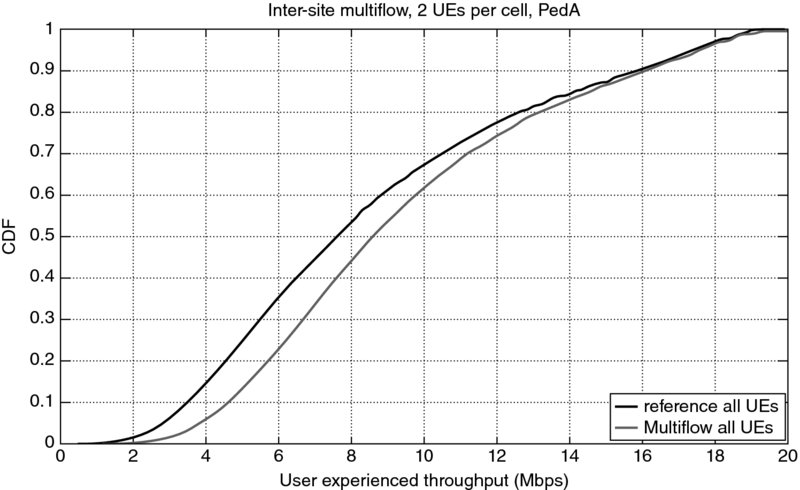
Figure 9.11 Cumulative probability distribution of user throughputs with and without Multiflow
From the perspective of the ITU IMT-Advanced requirements, HSPA+ Multiflow helps achieve the required performance at the cell edge.
9.4.5 Performance in Different ITU-R Scenarios
The key parameters of the ITU-R deployment environments are described in Table 9.5.
Table 9.5 Key deployment scenario parameters for the system performance evaluation
| Indoor hotspot
InH |
Urban micro
UMi |
Urban macro
Uma |
Rural macro
RMa |
|
| BS-to-BS distance | 60 m | 200 m | 500 m | 1732 m |
| BS antenna elements | Up to 8 Rx and 8 Tx | |||
| Total cell Tx power | 21 dBm/20 MHz | 41 dBm/10 MHz | 46 dBm/10 MHz | 46 dBm/10 MHz |
| BS antenna height | 6 m, ceiling mounted | 10 m, below rooftop | 25 m, above rooftop | 35 m, above rooftop |
| BS antenna gain | 0 dBi | 17 dBi | 17 dBi | 17 dBi |
| Device antenna elements | Up to 2 Rx and 2 Tx | |||
| Device Tx power | 21 dBm | 24 dBm | 24 dBm | 24 dBm |
| Device speed (high speed) | 3 km/h (10 km/h) | 3 km/h (30 km/h) | 30 km/h (120 km/h) | 120 km/h (350 km/h) |
| Carrier frequency | 3.4 GHz | 2.5 GHz | 2.0 GHz | 800 MHz |
The system performance requirements for a candidate IMT-Advanced radio technology are shown in Table 9.6. The evaluation criteria state that it is sufficient to meet each requirement type in three out of four deployment scenarios to qualify as an IMT-Advanced radio.
Table 9.6 IMT-Advanced system performance requirements
| Indoor hotspot | Urban micro | Urban macro | Rural macro | |
| InH | UMi | UMa | RMa | |
| Downlink average spectral efficiency | 3.0 bits/s/Hz | 2.6 bits/s/Hz | 2.2 bits/s/Hz | 1.1 bits/s/Hz |
| Downlink cell edge spectral efficiency | 0.1 bits/s/Hz | 0.075 bits/s/Hz | 0.06 bits/s/Hz | 0.04 bits/s/Hz |
| Uplink average spectral efficiency | 2.25 bits/s/Hz | 1.8 bits/s/Hz | 1.4 bits/s/Hz | 0.7 bits/s/Hz |
| Uplink cell edge spectral efficiency | 0.07 bits/s/Hz | 0.05 bits/s/Hz | 0.03 bits/s/Hz | 0.015 bits/s/Hz |
| High speed spectral efficiency | 1.0 bits/s/Hz | 0.75 bits/s/Hz | 0.55 bits/s/Hz | 0.25 bits/s/Hz |
| VoIP capacity | 50 users/MHz | 40 users/MHz | 40 users/MHz | 30 users/MHz |
The evaluation of Long Term HSPA Evolution performance against these requirements was both a major simulator development effort and a long-lasting simulation campaign. The following figures (Figures 9.12, 9.13, 9.14, and 9.15) show the simulation results against the ITU IMT-Advanced set requirements.
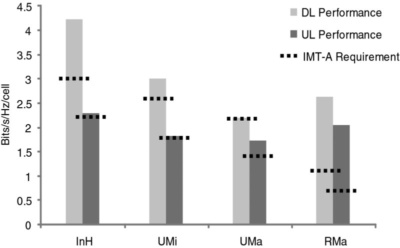
Figure 9.12 LTHE cell average spectral efficiency vs. IMT-A requirement
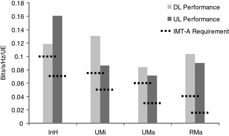
Figure 9.13 LTHE cell edge spectral efficiency vs. IMT-A requirement
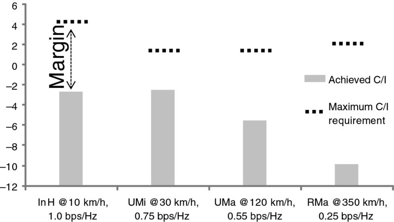
Figure 9.14 LTHE high speed mobility traffic channel performance vs. IMT-A requirement
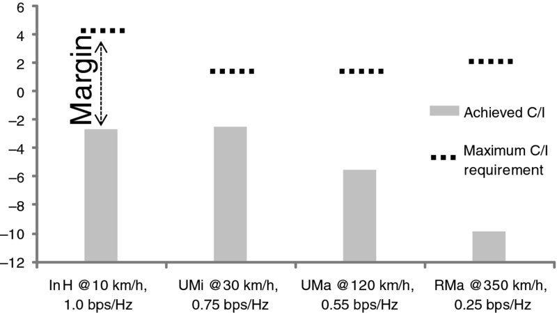
Figure 9.15 LTHE voice outage performance vs. IMT-A requirement
As shown, Long Term HSPA Evolution meets all the IMT-Advanced performance requirements. The results do not include cell edge spectral efficiency features, such as scenario-optimized scheduler or HSPA+ Multiflow, but assume a fairly advanced interference suppressing receiver in the device.
9.4.6 Latency and Handover Interruption Analysis
Table 9.2 listed the ITU-R IMT-Advanced requirements on latency and handover interruption as well as what the UMTS system was already able to achieve. The requirements should be understood as limits that the technology can fulfill, with state-of-the-art implementation and best case deployment.
The user plane latency was analyzed in the same way as was done for LTE-Advanced, looking at the lowest possible air interface delay, and coupling it with HARQ round-trip time averaged with the HARQ retransmission probability. These components are illustrated in Figure 9.16 and Table 9.7.
Table 9.7 HSPA user plane latency analysis
| Downlink | Uplink | |
| NodeB processing | 2 ms | 2 ms |
| Air interface delay | 3.33 ms | 2 ms |
| UE processing | 2 ms | 2 ms |
| Total with zero BLER | 7.33 ms | 6 ms |
| HARQ RTT | 12 ms | 16 ms |
| Total with 10% BLER | 8.53 ms | 7.6 ms |
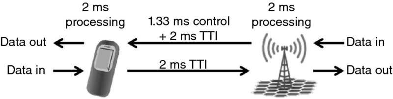
Figure 9.16 HSPA user plane latency components
Control plane latency analysis also followed the practice used in performance evaluation of LTE-Advanced, consisting of the best case latencies from the UE initiating a connection request to the dedicated connection being set up. The latency analysis is detailed in Table 9.8.
Table 9.8 HSPA control plane latency analysis
| Delay component | Delay [ms] |
| Average delay due to RACH scheduling period | 0.66 |
| Time from the beginning of PRACH preamble to the beginning of acquisition indication and channel assignment | 2 |
| Average time from the beginning of AICH to the beginning of UE uplink transmission start | 3.33 |
| Time from start of UE uplink transmission to start of UL data transmission (UL synch) | 10 |
| Transmission of RRC and NAS request | 2 |
| NodeB and RNC processing delay (L2 and RRC) | 10 |
| Transmission of RRC connection setup | 3.33 |
| Processing delay in the UE (L2 and RRC) | 12 |
| Transmission of RRC connection setup complete | 2 |
| Processing delay in collapsed architecture NB/RNC (Uu → Iu) | |
| Iu transfer delay | |
| CN processing delay (including UE context retrieval of 10 ms) | |
| Iu transfer delay | |
| Processing delay NodeB amd RNC (Iu → Uu) | 10 |
| Transmission of RRC security mode command and connection reconfiguration (+TTI alignment) | 3.67 |
| Processing delay in UE (L2 and RRC) | 16 |
| Total delay (Requirement 100 ms) | 75 |
Due to the make-before-break nature of soft handover there is no interruption in the intra-frequency handover of WCDMA. HSDPA intra-frequency handover with Multiflow also experiences zero break as first the UE connects to the target cell, and only after that does the UE disconnect from the source cell. Furthermore, with HSPA technology it is possible, with RNC based bicasting and using enhanced HSDPA serving cell change, to achieve zero-break even without Multiflow. In uplink, HSUPA benefits from soft handover and thus by definition there is no break in uplink intra-frequency handovers.
Inter-frequency and inter-band handovers are effectively the same and when executing intra-BTS timing maintained hard handover, even though the handover is break-before-make, the reacquisition of the synchronization is extremely fast. Thus the very basic Release 99 WCDMA standard was already able to meet the handover interruption requirements set much later for IMT-Advanced.
9.5 Conclusions
In this chapter the features added in Release 11 HSPA to allow the IMT-Advanced requirements to be met were analyzed. It could be concluded that with the introduction of
- eight-carrier aggregation, giving up to eight times better user performance;
- 4 × 4 MIMO in the downlink, increasing peak data rates, and improving system performance;
- uplink beamforming, 2 × 2 MIMO and 64QAM; uplink improvements increase the peak data rate, user performance, and cell capacity;
- Multiflow – increases downlink user throughputs at the cell edge;
Release 11 HSPA, sometimes referred too as Long Term HSPA Evolution, can also meet the criteria as IMT-Advanced technology as defined by the ITU-R. To meet the increased network capacity demand caused by growing mobile data traffic, HSPA has continued to be improved in parallel with LTE and LTE-Advanced.
HSPA is currently the radio access technology serving the most wireless broadband users worldwide and the load on the system is expected to increase further in the coming years, thus creating demand for performance improvements in the future, facilitating introduction of new performance improvements features to the commercial HSPA networks expected to be serving more than 2 billion users worldwide by end of 2014.
References
- Holma, H. and Toskala, A. (2012) LTE Advanced: 3GPP Solution for IMT-Advanced, John Wiley & Sons, Ltd, Chichester.
- Holma, H. and Toskala, A. (2010) WCDMA for UMTS, 5th edn, John Wiley & Sons, Ltd, Chichester.
- ITU-R report, M.2134, “Requirements related to technical performance for IMT-Advanced radio interface(s)”.