
15
LTE Interworking
Harri Holma and Hannu Raassina
15.1 Introduction
Long Term Evolution (LTE) networks are being rapidly rolled out but the deployment process will take some time. Therefore, there is a clear need for smooth interworking between 3G and LTE for coverage, capacity, and for service reasons. The interworking requires a number of different functionalities depending on the LTE use cases. We can differentiate the following phases of LTE network deployment:
- Data only LTE network for USB modems but not for smartphones. The interworking for the data connection is required from 3G to LTE when LTE coverage is available. Also the coverage trigger from LTE to 3G is needed to transfer the connection to 3G when running out of LTE coverage area.
- Data only LTE network, also for smartphones. The interworking solution for voice calls is required, Circuit Switched (CS) fallback, to move the UE from LTE to 3G when the voice call is initiated.
- Enhanced interworking for data, including redirection and handovers to minimize the connection break during the data transition. The first phase of data interworking may rely on simple functions based on reselections.
- Voice over LTE (VoLTE) to also carry voice in LTE requires interworking between Voice over IP (VoIP) and CS voice when running out of LTE coverage area. This is called Single Radio Voice Call Continuity (SRVCC).
The selection of the target system and target cell in the idle mode is done by the UE based on the network parameters, and the UE has no freedom in the system selection. The idle mode parameters are typically defined so that the UE will camp in LTE as long as the LTE signal level exceeds a predefined threshold. Also, network parameters typically allow the UE to move from 3G to LTE as soon as the LTE signal is strong enough. The network can move UEs between LTE and 3G also by redirection and handover procedures. The redirection is controlled by the network but the resources in the target cell are not reserved. In the case of handover, the resources in the target cell are reserved.
Several different network controlled triggers can be used for moving UEs. The different triggers for interworking are illustrated in Figure 15.1. The coverage trigger from LTE to 3G is needed when running out of LTE area. One such trigger is needed for the packet data connection to continue the data transfer in 3G, and a separate trigger is needed for the VoLTE connection to continue the voice call in the CS network in 3G. A trigger is also required to get the UE back from 3G to LTE when it is again in the LTE coverage area. It is also possible to utilize service-based or load-based interworking between LTE and 3G to balance the loading and the network utilization. CS fallback is one specific case of interworking where UE is moved from LTE to 3G for the voice call if VoLTE is not supported.
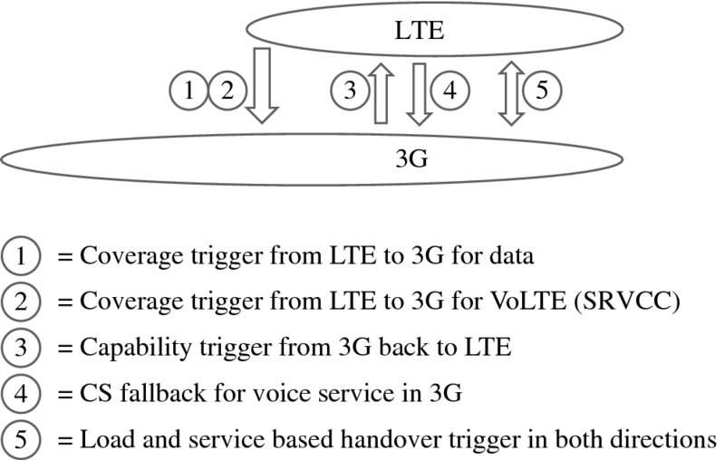
Figure 15.1 Inter-system mobility triggers
This chapter describes the interworking functionalities for data connections in Section 15.2 and for CS fallback in Section 15.3, discusses parameter optimizations in Section 15.4, presents SRVCC in Section 15.5, and concludes in Section 15.6. Interworking mobility methods are mainly described between LTE and 3G networks, but similar methods are also introduced for LTE and 2G networks. Depending on the mobile operator strategy and network rollouts, the mobility may be implemented only between LTE and 3G networks or between LTE and 2G networks as well.
The 3GPP radio protocols can be found in [1] for 3G and in [2] for LTE. The performance requirements for the interworking are defined in [3] for 3G part and in [4] for LTE part. The circuit-switched core network protocols are shown in [5] and the evolved packet core network protocols in [6]. The architecture for CS fallback is described in [7] and for SRVCC in [8].
15.2 Packet Data Interworking
The data interworking between LTE and 3G can utilize reselections, redirections, and hand-overs. In the early phase, reselection and redirection are used to move the UE from LTE to 3G while later handover can also be utilized to minimize the connection break. The return from 3G to LTE can use UE-based reselection or network controlled redirection and handover. The redirection and handover allow UE to get back faster to LTE. It may be hard to get UE quickly back to LTE if we only rely on reselection, since reselection is possible only if UE is in idle mode or a Cell/URA_PCH state long enough. The ongoing data transfer can delay the reselection-based mobility from 3G to LTE. These procedures are summarized in Figure 15.2.
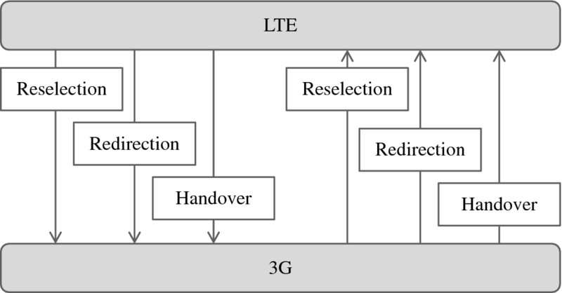
Figure 15.2 LTE to 3G packet data interworking features
The different interworking techniques are compared in Table 15.1. The reselection is based on the UE measurements without any network control, while redirection and handover are controlled by the network. The target cell measurements can be used with redirection, but it is also possible to make redirection blindly to a predefined target frequency without any measurements. Resource reservation in the target cell is done in the case of handover but not for redirection. The connection break is shortest with handover: typically below 1 s. The break with redirection and reselection from 3G to LTE is short, even below 2 s, while the break from LTE to 3G can be 5 to 10 s. The redirection from 3G to LTE needs RRC connection and Tracking Area Update to be performed on the LTE side, which is quick. The redirection from LTE to 3G needs more SIB reading, Location and Routing Area Updates, context modifications, and radio bearer setups. The reselection procedure takes more time than redirection because UE first needs to make measurements of the target cell and the UE needs to be in idle state, URA_PCH, or Cell_PCH before the actual decision to perform the reselection is made. Therefore, the UE can move faster from 3G to LTE with redirection than with reselection. The fast return to LTE is relevant after the CS fallback call.
Table 15.1 Comparison of packet data interworking features
| Reselection | Redirection | Handover | |
| Network controlled | No | Yes | Yes |
| Target cell measurements | Yes | Possible but not always used (blind) | Yes |
| Target cell resource reservation | No | No | Yes |
| Connection break | LTE to 3G: <10 s 3G to LTE: <2 s |
LTE to 3G: <10 s 3G to LTE: <2 s |
<1 s |
Redirection from 3G to LTE can be used when the UE is in Cell_DCH state. The UE-based reselection is used when the UE is in Cell_PCH, URA_PCH, or in idle state. There used to be no possibility of going to LTE while in Cell_FACH state. The reselection capability from Cell_FACH to LTE was added only in 3GPP Release 11 as one of the sub-features of Further Enhanced FACH (FE-FACH), see Chapter 4. Cell_FACH state is normally very short and this limitation is not any major concern. But some of the 3G networks did not have Cell_PCH nor URA_PCH state active, and used instead long inactivity timers on Cell_FACH. That made it difficult for UEs to get back from 3G to LTE.
The redirection functionality can be used after the CS voice call has ended in 3G and the UE needs to be moved back to LTE. The redirection can be done in the RRC connection release in 3G when the voice call has ended. The redirection can also be used to push the UE back to LTE when the UE enters the LTE coverage area. The RNC can decide to use redirection when there is no data transfer happening in Cell_DCH state in order to minimize the impact of the redirection to the end user performance. The options for getting UE from 3G to LTE are illustrated in Figure 15.3.
When the CS fallback call is completed in 3G, UE will reselect back to LTE. The reselection procedure is shown in Figure 15.4. UE needs to run a Location Area Update (LAU) either during the CS fallback setup or after the CS call has been disconnected. The Location Area Update in 3G is required to make the incoming voice calls to route the paging to the right network. The Location Area Update takes a few seconds. It then takes some time for the UE to find LTE cells and make a Tracking Area Update to LTE. The total delay is typically 10 s to get back to LTE after the CS voice call is completed. The return to LTE may take more time even if the LTE coverage is good enough, if the UE remains in Cell_DCH or in Cell_FACH where cell reselection to LTE is not possible.
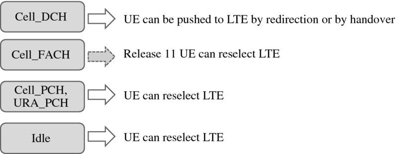
Figure 15.3 Options for getting the UE from 3G to LTE
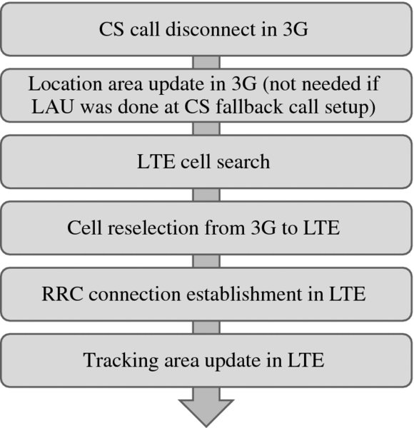
Figure 15.4 Reselection from 3G to LTE after a CS fallback call
Reselection takes quite some time and also causes a noticeable break in the data transfer. Redirection or handover allow the UE to get quickly back to LTE after the voice call, improving the end user performance. The data interruption time with redirection is longer than with handover, but redirection has the benefit that it is relatively easy to create, maintain, and operate compared to the handover. The UE needs to know only the target frequency but no cell specific information in the case of redirection. With redirection, there is no need to maintain and update any cell specific neighbor information between LTE and 3G. In the case of handover, the neighbor information needs to be maintained between LTE and 3G. However, maintaining neighbor information linked to LTE and 3G relations could be more and more automatized in the future due to network and UE evolution. When the commercial Self Organizing Networks (SONs) evolve, UEs can report missing LTE to 3G neighbors to the network. Based on these UE reports, the network can create the necessary LTE-3G cell pair relations and store them in the network database.
The interruption time with handover is shorter than redirection since the resources in the target system are reserved in the case of handover. In the case of redirection, UE needs to perform registration to 3G and establish a data connection to the 3G network. This may increase the data interruption up to 12 s. The interruption time with redirection is shown in Figure 15.5. The solutions for speeding up redirection are considered in Section 15.3 together with CS fallback optimization.
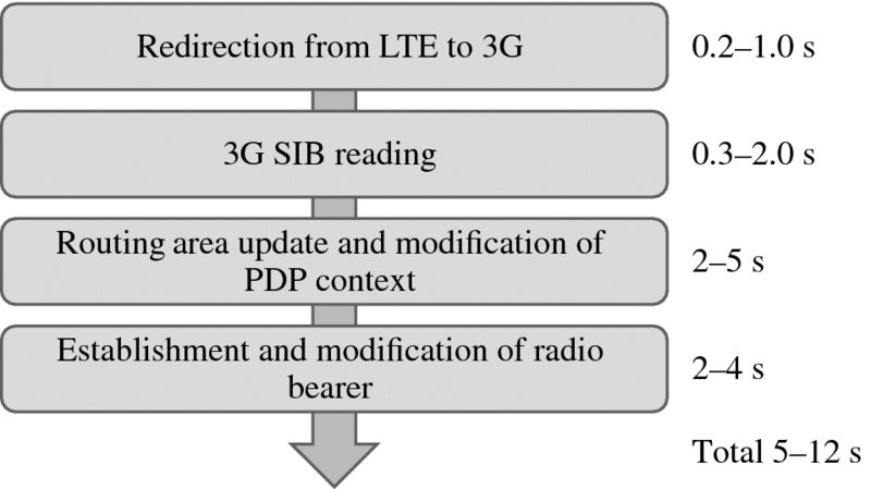
Figure 15.5 Interruption time with redirection from LTE to 3G
Example packet handover measurements from LTE to 3G are shown in Figure 15.6. The break from the control plane point of view is just 0.2–0.3 s. The break from the user plane point of view is below 1 s, which is a major improvement compared to reselection and redirection.
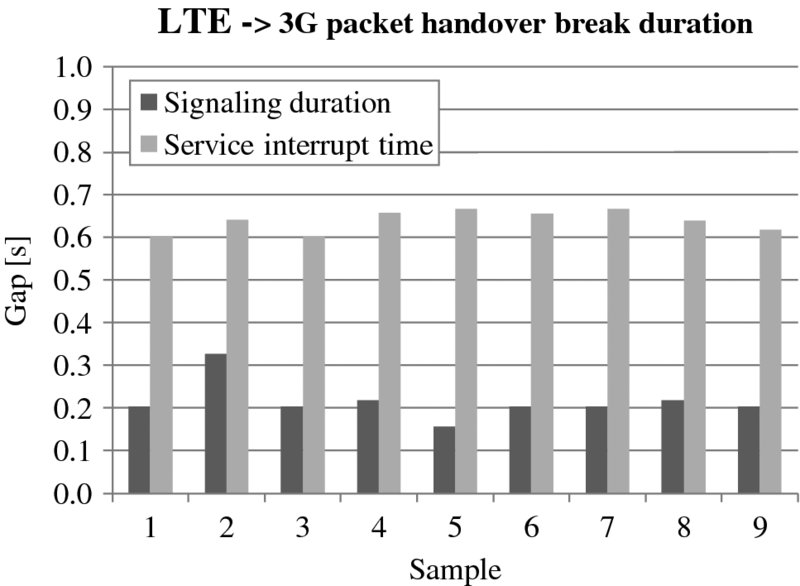
Figure 15.6 Handover measurements from LTE to 3G
15.2.1 Example Trace of 3G to LTE Cell Reselection
This example describes a typical scenario in 3G to LTE cell reselection. System information block type 19 (SIB19) is a broadcasted signaling message in 3G, which informs the UE of the criteria, how to perform 3G to LTE cell reselection. SIB19 information is shown in Figure 15.7 and explained below.
| earfcn: 1300 | Target LTE layer belongs to LTE band 3 meaning 1800 MHz downlink carrier frequency with E-UTRA Absolute Radio Frequency Channel Number 1300. |
| Measurement bandwidth: | Measurement bandwidth of target LTE layer here is 50 PRBs (mbw50). It means that target layer RSRP (Reference Signal Received Power) is measured over 10 MHz bandwidth. |
| Priority: 6 | Target LTE layer has priority 6 in the eutra-Frequency And Priority Info List. Priority range is between 0…7. Value 7 means highest priority |
| Priority: 3 | Serving 3G cell has priority 3 in the utra-Priority Info List, which is lower priority, than target LTE layer has. |
| qRxLevMinEUTRA: −66 | Minimum required Rx level of the target LTE cell RSRP is 2 × −66 dBm = −132 dBm |
| threshXhigh: 10 | Since LTE layer has higher priority compared to 3G layer, 2 × 10 dB = 20 dB threshold is added on top of qRxLevMinEUTRA. |
| eutraDetection | Defines whether UE in idle mode may detect the presence of LTE cell. |
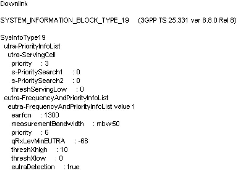
Figure 15.7 SIB19 in 3G
Based on this information received in SIB19, the UE knows that signal level of the target LTE 1800 MHz cell with EARFCN 1300 must exceed RSRP = −132 dBm + 20 dB = −112 dBm, before cell reselection from 3G to LTE can be done. The actual cell reselection decision is made by the UE itself based on its repetitive target LTE layer measurements. The requirement in 3GPP specification [1] is that the UE must measure LTE cells at least every 60 s in the case of one target LTE frequency and every 120 s in the case of two target LTE frequencies.
The UE measurement logs from Anite Nemo outdoor tool are shown in Figure 15.8. Based on log files, the test terminal measured the target LTE layer every 7th second. When the RSRP of the target LTE cell was strong enough, meaning the RSRP exceeding the threshold –112 dBm defined by network parameters in SIB19, cell reselection from 3G to LTE was performed. Cell reselection from 3G to LTE is possible only in the case that UE is in idle mode or Cell/URA_PCH-state.
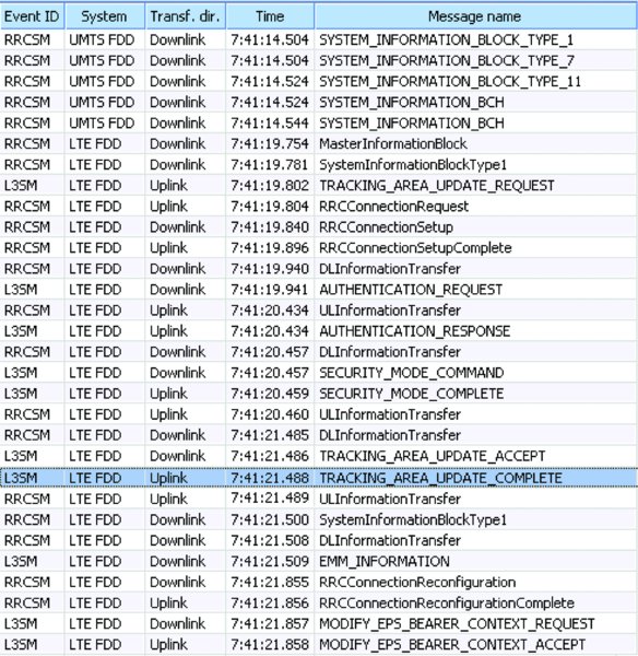
Figure 15.8 3G to LTE cell reselection with tracking area update
When entering LTE, the UE performs a Tracking Area Update to indicate its location to Mobility Management Entity (MME). Authentication, ciphering, and integrity checks are done with the Authentication and Security Mode procedures. During these phases, the integrity and encryption algorithms for the EPS session are agreed. Along with these, the UE needs to establish the RRC connection which is needed to maintain the connection between UE and LTE eNodeB.
In the case that the UE QoS subscription parameters differ in LTE compared to 3G, a ModifyEPSBearerContextRequest-message may be sent by the network to the UE to modify the EPS bearer context proper for LTE after the Tracking Area Update has been done. The maximum downlink and uplink bitrates may be modified in this EPS bearer context modification procedure. The context modification does not typically take more than 0.5 s.
15.2.2 Example Trace of LTE to 3G Redirection
This example shows blind redirection from LTE to 3G with an active packet connection. The UE asks for an RRC connection with RRCConnectionRequest with cause value Mobile Originated data in Figure 15.9. The UE already has the default EPS bearer context activated. Ciphering and integrity protection algorithms are agreed in the SecurityModeCommand for the active RRC connection. Since the UE informs in UECapabilityInformation that it supports InterRAT-mobility from LTE to 3G and 2G, eNodeB informs InterRAT-mobility criteria and related triggers in RRCConnectionReconfiguration-message.
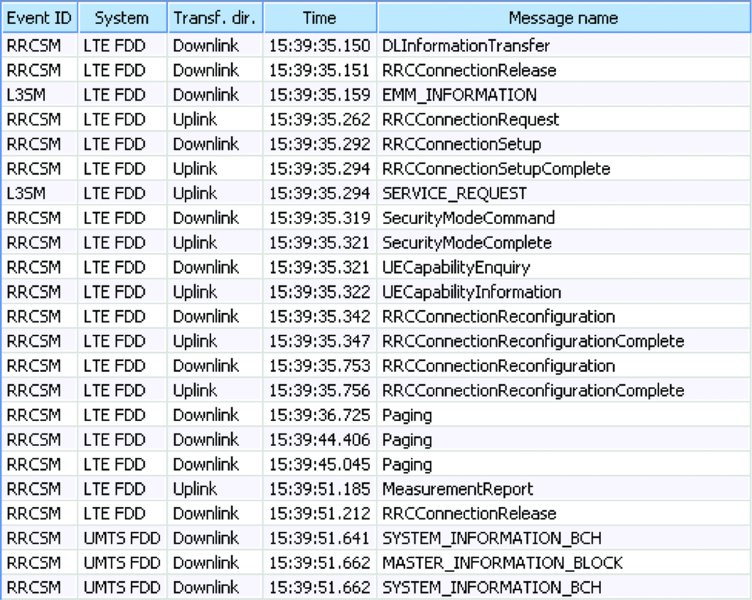
Figure 15.9 LTE to 3G redirection
LTE to 3G or 2G redirect triggers are presented in Figure 15.10. InterRAT-mobility is based on event triggering. This means that the UE reports to the network if a predefined event happens. EventA2 means that the serving LTE cell has become worse than the threshold.
| Hysteresis: 0 | Hysteresis for A2 event |
| A2-Threshold RSRP: 18 | UE must send a measurement report to the network if RSRP goes below −140 dBm + eventA2threshold + hysteresis = −140 dBm + 18 dB + 0 dB = −122 dBm |
| timeToTrigger: ms256 | A2 criteria must be valid at least 256 ms, before measurement report A2 can be sent |
| triggerQuantity: rsrp | RSRP is the triggering quantity for LTE to 3G redirect |
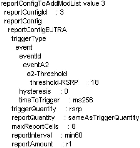
Figure 15.10 LTE to 3G redirection threshold in RRC connection reconfiguration
When LTE RSRP goes below the eventA2 threshold, the UE sends a measurement report to the network. In this example, the UE indicates in the measurement report that the measured RSRP has gone already to −140 dBm + 15 dB = −125 dBm, which is below the eventA2 threshold defined LTE to 3G redirect threshold of −140 dBm + 18 dB = −122 dBm. The measurement report is shown in Figure 15.11.
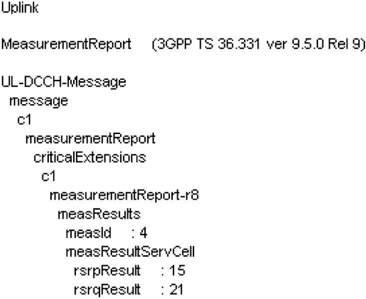
Figure 15.11 Measurement report for eventA2
Based on that measurement report and LTE to 3G redirect mobility relation defined in the network, eNodeB commands the UE to 3G network with the RRCConnectionRelease-message. The example in Figure 15.12 shows a blind redirect method where eNodeB informs the UE only about the target 3G UTRAN Absolute Radio Frequency Channel Number (UARFCN). Based on UARFCN utra-FDD: 10 837 the UE knows that the target 3G belongs to a 2100 MHz network. After this, the UE leaves the LTE network and starts seeking and camping on the 2100 MHz 3G cell with UARFCN 10 837.
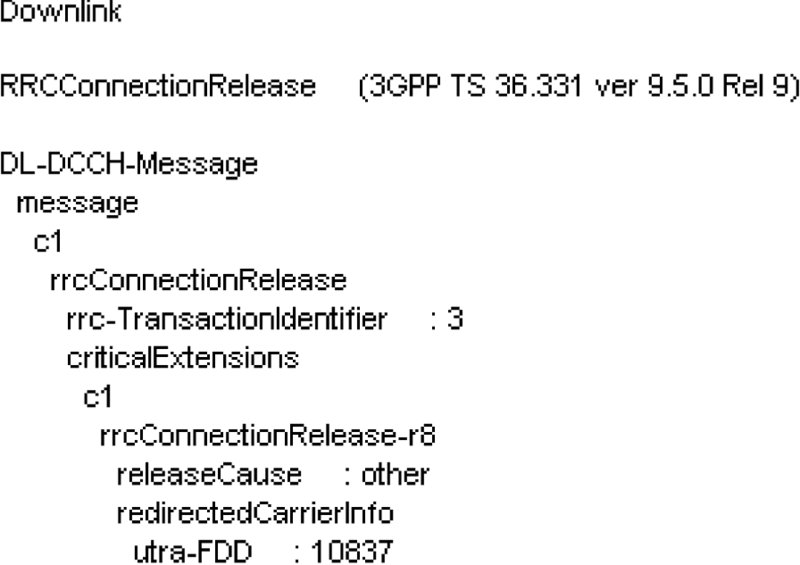
Figure 15.12 Redirect from LTE to 3G with RRC connection release
UE camping to 3G is shown in Figure 15.13. When the UE has synchronized to the 3G cell, it starts reading 3G system information. The system information presents, for example, the following information to the UE: Idle mode mobility criteria in 3G presented in SIB3, 3G to LTE mobility criteria in SIB19, and uplink interference information in SIB7. If the camped 3G cell is the same cell where the UE last time camped in 3G, the UE may have stored part of that specific 3G cell system information to its memory like the 3G cell neighboring cell information stored in SIB11. In this example, it can be seen that SIB11 is not read. It is stored to the UE's memory from the previous mobility session which was done to this same 3G cell.
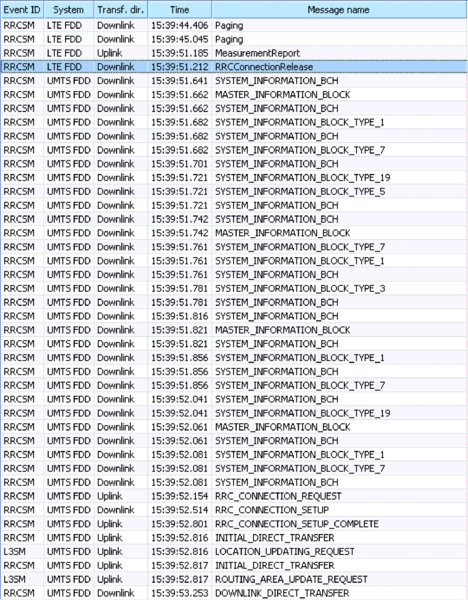
Figure 15.13 Camping to 3G after LTE to 3G redirection
After all the relevant system information is received, UE can start RRC connection establishment with cause value “registration.” That is needed for the Location and Routing Area Updates, presented in Figure 15.14, which are needed for the network to know that the UE is now in the 3G network under the specific 3G Location and Routing areas defined with Location and Routing Area Codes (LAC, RAC). The UE identity is verified with IdentityRequests and indicated with International Mobile Subscriber Identity (IMSI) and International Mobile Station Equipment Identity and Software Version (IMEISV). Also, the authentication and ciphering are handled and agreed with the related procedures. 3G mobility criteria and connected mode neighbor lists are informed with MeasurementControl-messages. After the Routing Area Update is accepted, the UE context is modified with ModifyPDPContextRequest to meet the 3G QoS parameters, which are defined in the network based on customer subscription. For example, the maximum bitrates for downlink and uplink for 3G connection are set here.
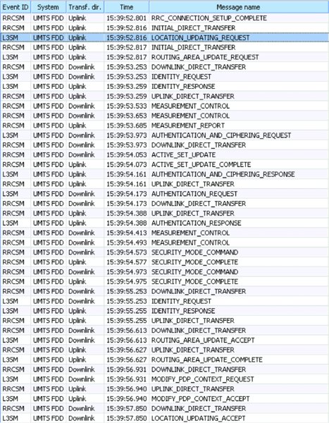
Figure 15.14 Mobility procedures in 3G after redirection from LTE
After the PDP context is modified, UE may send a ServiceRequest to the network including information on active PDP context and pending uplink data. Pending data triggers the setup of radio bearer, which is modified with a RadioBearerReconfiguration to provide a packet data connection. In this example, the packet data connection was reconfigured to the HSPA connection with 21 Mbps downlink and 5.8 Mbps uplink capability. The data transfer can continue now. The 3G radio bearer setup is shown in Figure 15.15.
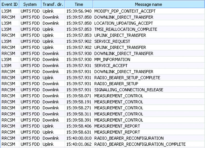
Figure 15.15 3G Radio bearer setup in 3G after LTE to 3G redirection
In this example, the data outage was around 10 s starting from LTE to 3G redirect triggered by RRC connection release in LTE and finally ending at RadioBearerReconfiguration in 3G.
15.3 Circuit-Switched Fallback
The target of the CS fallback is to use the existing 3G or 2G network to carry voice calls while the LTE network is used for data connections. CS fallback allows provision of voice services for LTE smartphones without implementing VoIP in LTE. CS fallback is the main voice solution in LTE smartphones and networks currently. The CS fallback can be targeted to 3G, GSM, or CDMA-1X. The most common target system is 3G WCDMA.
The CS fallback procedure is illustrated in Figure 15.16 and in Figure 15.17. The CS fallback UE makes a combined attachment to the LTE network and the MME executes a Location Area Update towards a serving MSS (Mobile Switching Center Server) to announce the presence of the UE to the CS core network. This procedure uses the SG's interface between MME and MSS. MSS then knows the UE's Location Area and serving MME, and can thus forward the paging message to the Mobility Management Entity (MME) which sends paging to the correct Tracking Area. When MME has sent the paging, the UE establishes an RRC connection in LTE and responds to the paging with an Extended Service Request to MME, which forwards it to MSS. The MME indicates eNodeB to move the UE to 3G or 2G by sending an Initial Context Setup, and the eNodeB redirects the UE to the 3G network. The UE finds the 3G target cell and establishes a RRC connection. The UE may need to read the System Information Block (SIB) in the target cell. The UE will then establish a RRC connection to 3G. The UE may also need to perform a Location Area Update. If the UE does not perform a Location Area Update, it sends a Paging Response to the MSC, which continues the call setup. The Routing Area Update in 3G runs in parallel to the CS call setup and does not impact the call setup time.
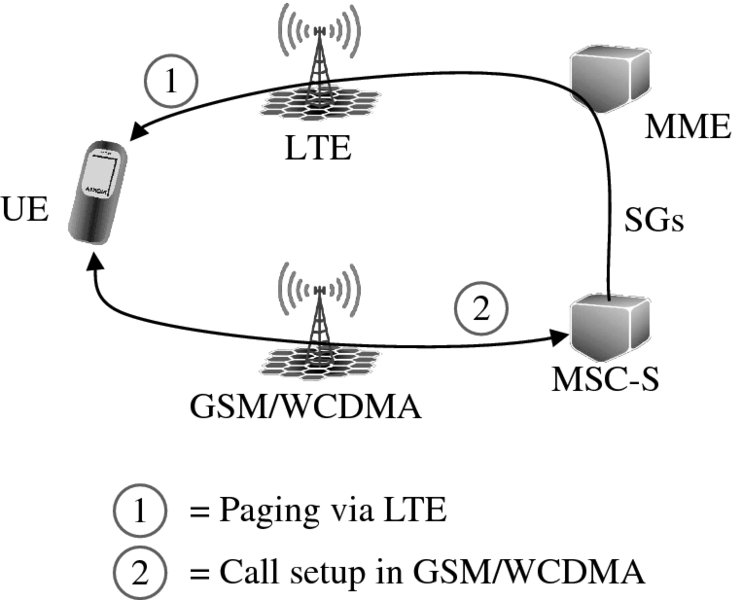
Figure 15.16 CS fallback functionality
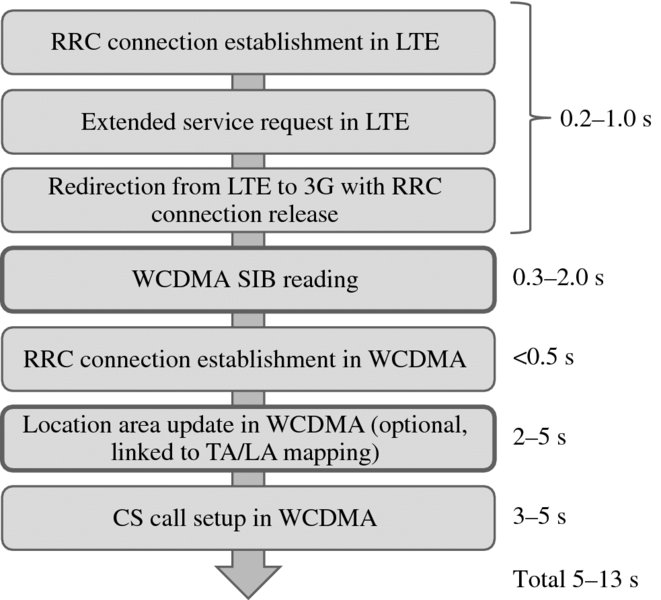
Figure 15.17 CS fallback call setup flow
The main factors impacting the CS fallback setup time are SIB reading in WCDMA and the Location Area Update in WCDMA. The setup time can be minimized by avoiding SIB reading and by avoiding Location Area Update. There are multiple solutions to avoid SIB reading or part of the SIB reading. It takes typically most of the time to read the neighbor list information stored in SIB11/12:
- 3G SIB delivery via LTE: the MME provides 3G SIB to the UE via the LTE network. This procedure is normally called Release 9 CS fallback.
- Deferred 3G SIB reading: the UE can start the Location Area Update before all SIBs are read. The 3G network will provide the SIB information on a dedicated control channel after the call setup is completed.
- UEs can remember 3G SIB if CS fallback happens for a second time in a row to the same cell. No network features are needed for this.
The Location Area Update can be avoided by implementing a geographically correct mapping between Tracking Areas and Location Areas to the network. The mapping refers to a database in MME managing the relationship between geographically overlapping Tracking Areas and Location Areas. The corresponding Location Area Code is informed to the UE in the LTE network Tracking Area Update procedure with the Tracking Area Update Accept-message or already in the LTE attach phase with the Attach Accept-message. Location Area Update during CS fallback can be avoided if SGs interface is enabled to MSC-Server and Tracking Area/Location Area mapping matches with the Tracking Area and Location Area combination observed by the UE during mobility between LTE and 3G. The overlay solution refers to the case where at least one, but not all, of the MSC-Servers have the SGs interface. However, typically only one CSFB MSC-Server has SGs interface in this type of solution. In the terminating call case, CSFB MSC-Server pages the UE in LTE via MME in the same way as in 2G/3G. After the paging, the UE performs CSFB to 2G/3G MSC-Server and proceeds as follows in the two cases:
- CSFB overlay case: UE performs a Location Area Update as MSC-Server has changed during the CSFB procedure.
- SGs interface for CSFB in every MSC-Server: UE responds with a Paging Response message to the same MSC-Server and avoids the time consuming Location Area Update procedure.
If an overlay MSC-Server solution is used, then all Tracking Areas, which are not overlapping with the overlay MSC-Server coverage area, are mapped to a single Location Area, which can be termed a virtual location area that does not reflect any real 3G Location Area. This method forces the UE to perform a Location Area Update each time when moving from LTE to 3G to the virtual location area during CS fallback call setup, since the actual 3G Location Area Code read from 3G system information differs from this pre-defined virtual Location Area Code informed by the LTE network based on the mapping table. The CSFB call is then routed via the MSC-Server that has SGs interface. These two CSFB architecture solutions are shown in Figure 15.18.
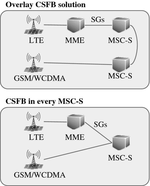
Figure 15.18 Overlay CSFB solution and CSFB in every MSC-S
The increase in the call setup time with CS fallback compared to a 3G CS call is shown in Table 15.2. CS fallback can bring a noticeable increase to the call setup time in the case that there is long neighbor list in the target 3G cell or the need to perform a Location Area Update in 3G. On the other hand, the additional setup time can be made below 1 s if the UE does not need to read the full SIB and if the UE does not need to run a Location Area Update. Figure 15.19 shows example setup time measurements in a well-planned live network comparing CS fallback from LTE to 3G and CS call in 3G. The average increase in the setup time is 0.7 s, which provides good end-user performance.
Table 15.2 Call setup time increase with CS fallback
| Location area update avoided | With Location Area Update | |
| With 3G SIB reading | 0.5–3.0 s | 2.0–8.0 s |
| Skip 3G SIB reading (Deferred SIB or Release 9 CSFB) | <1.0 s | 1.5–6.0 s |
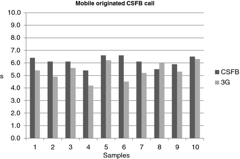
Figure 15.19 CS fallback setup time measurements
If there is a parallel data session together with the voice call, it is handed over from LTE to 3G during the CSFB procedure. The user can then continue the data connection during the CS voice call. The data connection might be reconfigured up to HSPA data rates, but support of HSPA functionality during an ongoing voice call is network dependent.
The monitoring of the CSFB success rate needs to combine information from LTE radio, WCDMA radio, and from MME and MSS. The problem with core network counters is that they give the performance statistics only on the MME/MSS level but not on the cell level. The radio counters provide cell-level information but the end-to-end view is missing since the first part of the CSFB procedure can be monitored in the LTE network and the actual call setup in the WCDMA network. 3GPP Release 9 adds an option that the UE can indicate in WCDMA that the call is a CSFB case and not a normal 3G call.
15.3.1 Example Circuit-Switched Fallback with Location Area Update
This example describes LTE CS fallback to 3G with blind redirect for the incoming call with an overlay MSC architecture. In this case, the UE must typically perform a Location Area Update before the actual 3G call setup can start. The UE is initially in LTE in idle mode and receives a Paging-message from the MME due to the incoming voice call in Figure 15.20. The UE establishes RRC Connection with a cause value: mt-Access and responds to paging with ExtendedServiceRequest with a service type value: mobile terminating CS fallback. UE InterRAT capabilities are checked with UECapabilityEnquiry. If 3G support exists, the UE is redirected to 3G with a RRCConnectionRelease-message containing information on the redirect carrier frequency channel number, which in this case belongs to UMTS 2100 MHz band. The RRCConnectionRelease message is shown in Figure 15.21.
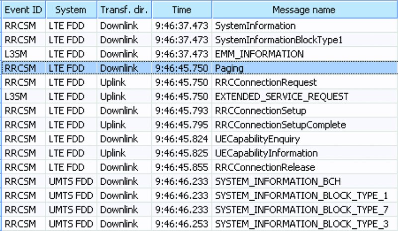
Figure 15.20 Redirect from LTE to 3G with CS fallback
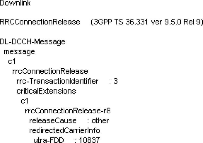
Figure 15.21 RRC connection release in LTE
After all the relevant broadcasted SIB information is read by the UE, it can start establishing a RRC connection with a cause value “registration” in Figure 15.22. The RRC connection is established for performing Location and Routing Area Updates, including agreement of ciphering with Security Mode procedures and identity and authentication requests. After the Location Area Update is accepted, the signaling connection is released with SignalingConnectionRelease towards the CS-domain in the case that the setup of the actual call has not started. The release of the signaling connection can be avoided by optimizing the core network settings.
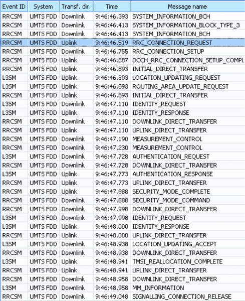
Figure 15.22 Registration to 3G
Since the signaling connection towards the core network domain was already released after the UE registered to 3G network, the UE must be paged again in 3G to start the actual call setup in Figure 15.23. This is done with a PagingType2-message with cause: TerminatingConversationalCall. PagingType2 is used in the case that the UE has an active RRC connection established. The UE responds to the paging with PagingResponse. The ciphering is handled by SecurityModeCommand. The setup message includes, for example, information on the calling number and it is informed by the core network. With the CallConfirmed-message the UE informs its 3G and 2G speech codec capabilities. The radio resources for speech call are set with the RadioBearerSetup-message. In this case, SF128 is reserved, meaning capacity suitable for 12.2 kbps 3G speech codec. In the Alerting-phase, the UE starts to play the UE ring tone for subscriber B and in the Connect-phase subscriber B answers the call and finally the call is connected successfully.
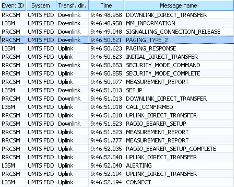
Figure 15.23 CS call setup in 3G
In this example, the total setup time of the incoming CSFB call with blind redirect to 3G took around 7 s.
15.3.2 Example Circuit-Switched Fallback without Location Area Update
This section shows an example CS fallback setup where no Location Area Update is required. When the UE moves from a 3G to a LTE network, it must perform a Tracking Area Update. In the TrackingAreaUpdateAccept-message, the LTE network informs on which Location Area in 3G mapped by operator should overlap with the serving Tracking Area in LTE. The message is shown Figure 15.24.
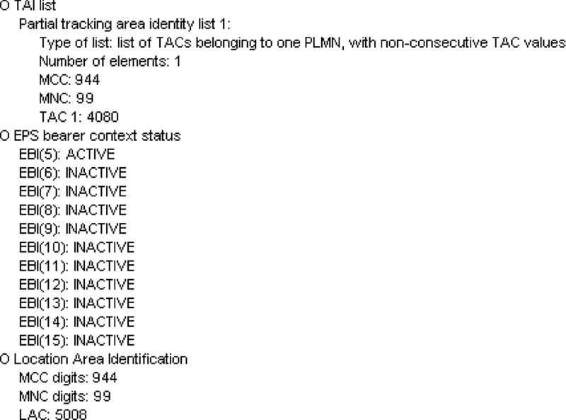
Figure 15.24 Tracking area/location area-mapping information in tracking area update accept-message
In this example, the UE receives information that Location Area Code (LAC) 5008 should have geographical overlap with Tracking Area Code (TAC) 4080. The UE stores this information in its memory. When the CS fallback call attempt in LTE is made, the UE again sends an ExtendedServiceRequest to the network in Figure 15.25, establishes a RRC connection, and is redirected to 3G with a similar RRCConnectionRelease-message that was already presented in Figure 15.21.
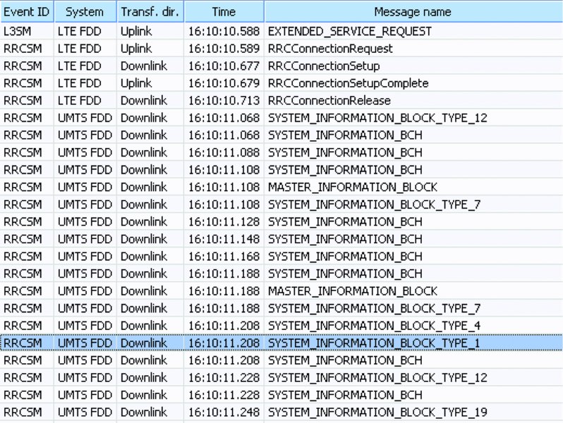
Figure 15.25 CS fallback redirect to 3G
The UE camps to the 3G cell that has the UARFCN informed in the RRCConnectionRelease-message and starts reading 3G system information. SystemInformationBlockType1 in Figure 15.26 shows the LAC of the 3G cell. In this example, mapping of LAC geographically to TAC matches, since LAC is 5008 also in the 3G system information. Since the 3G LAC informed in SIB equals the information given in LTE with the TrackingAreaUpdateAccept-message, the UE does not need to perform Location Area Updates anymore, which speeds up the call setup time in Figure 15.27. The UE establishes a RRC connection with cause: OriginatingConversationalCall, requests the Routing Area to be updated, which is done in parallel with the actual call setup. The call setup is initiated by the UE with a CMServiceRequest-message with service type info: Mobile originating call establishment. Finally, the Routing Area Update is accepted, the context is modified to meet the 3G QoS requirements, and the radio bearer setup is done to reserve resources from the radio network for speech call. Setup and call proceeding messages are run in parallel to the call setup. The call setup is finalized with the Connect-message in Figure 15.28. The CS fallback call setup took in this example 5.4 s, which is shorter than the example presented in Section 15.3.1, where a Location Area Update was required.
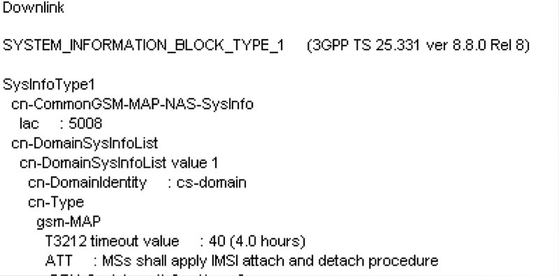
Figure 15.26 Location area code in 3G system information
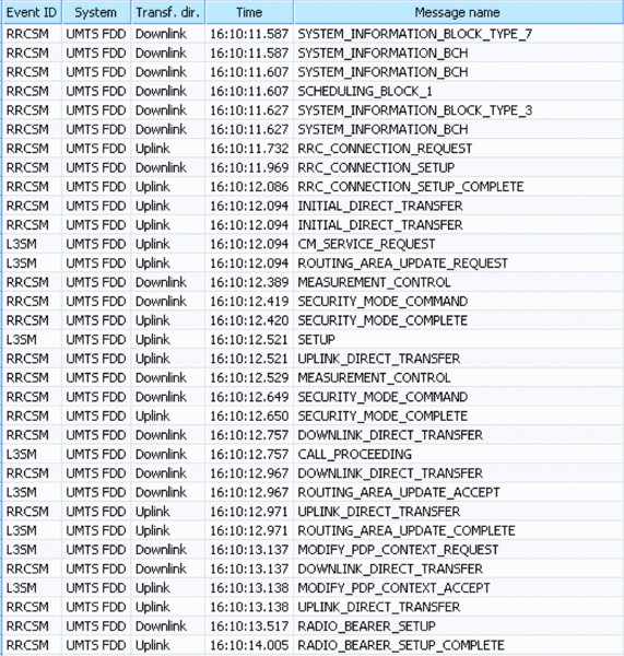
Figure 15.27 Call setup with no location area update
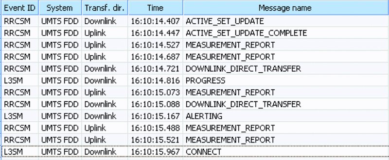
Figure 15.28 Call setup finalized
15.4 Matching of LTE and 3G Coverage Areas
The 3G system should preferably have a larger coverage area than LTE when transferring the UE from LTE to 3G. This aspect is especially true with CSFB functionality. When VoLTE is introduced to the LTE network, then the LTE coverage area can be larger than 3G.
The interworking between LTE and 3G provides smoother data and voice performance and simpler operability compared to the interworking between LTE and 2G. If the UE cannot find the target 3G system, it may drop out of the network coverage for short period of time. Such a case may happen if the LTE is deployed on low frequency (LTE800) while 3G uses high frequency (UMTS2100). The preferred solution would be to also have low band 3G together with low band LTE to provide similar coverage. This case is illustrated in Figure 15.29. If 3G coverage is smaller than LTE coverage, the following solutions may be needed
- Reduce the LTE coverage area by a lower transmit power or by a higher trigger level for the inter-RAT mobility.
- Increase the 3G coverage area by a higher transmit power, by lower inter-RAT mobility thresholds from 3G to 2G, or by new 3G base stations.
- Implement mobility from LTE also to 2G. In that case, inter-RAT measurements are needed to be activated to the network side to identify whether the target system providing sufficient coverage during Inter-RAT mobility is 3G or 2G. The inter-RAT measurements are done by the UE anyway in case of cell reselection. Blind redirection cannot be used because that feature must blindly use a predefined target system for each cell. The solution in that case should be redirection with measurements or handover with measurements. The mobility from LTE to 2G requires also that the LTE neighbor list includes 2G target frequencies.
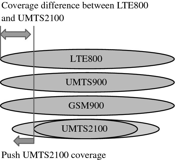
Figure 15.29 Inter-system mobility challenge if 3G coverage is smaller than LTE coverage
15.5 Single Radio Voice Call Continuity (SRVCC)
Voice over LTE (VoLTE) began commercially in 2012, but without any interworking to 3G CS voice. Such a solution is possible only with excellent LTE coverage. A handover from VoLTE to CS voice is required in typical cases. The handover is called Single Radio Voice Call Continuity (SRVCC) and is illustrated in Figure 15.30.
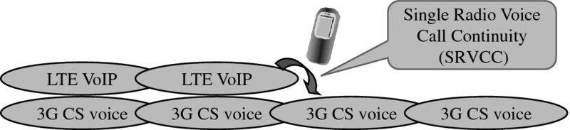
Figure 15.30 SRVCC handover from VoIP to CS voice
The main reason for SRVCC handover occurs when a UE with a VoLTE call runs out of the LTE coverage area. SRVCC consists of two phases: inter-Radio Access Technology (inter-RAT) handover and session transfer. Inter-RAT handover is similar to the packet handover but it is done from Packet-Switched VoIP to Circuit-Switched voice. Session transfer is a mechanism to move voice media anchoring from the Evolved Packet Core (EPC) to the CS core network. The MSS initiates the session transfer and the IMS keeps control of the user during the process. The eNodeB requests the MME to make a PS-to-CS handover for the UE and the MSS requests the 3G network to prepare for the incoming handover. The SRVCC related architecture and interfaces are shown in Figure 15.31. SRVCC architecture includes two radio networks, evolved packet core, CS core, and IMS. The large number of network elements increases the complexity of SRVCC.
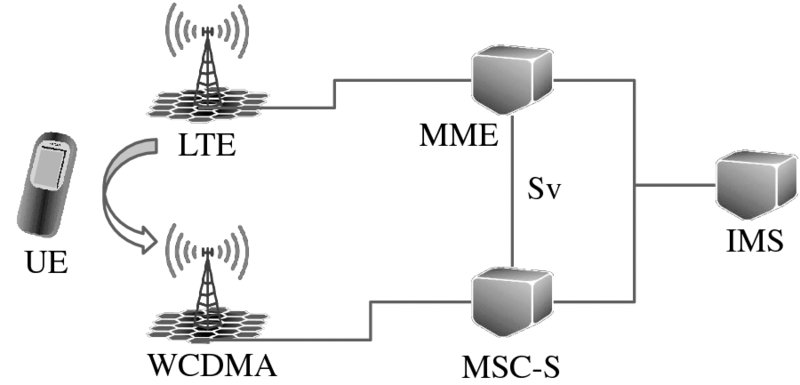
Figure 15.31 SRVCC architecture
The target is to keep the user plane connection break below 0.3 s [9] which makes SRVCC practically unnoticeable to the end user. Such a short voice interruption time is possible to reach as all CS side radio and voice core (MSC-Server/MGW) resources are reserved beforehand. In the case of SRVCC, there is no need for the time consuming Location Update procedure in any circumstances, as the SRVCC MSC-Server is doing that on behalf of the UE. Figure 15.32 shows voice interruption time measurements: the downlink interruption was 150 ms and uplink 250 ms. These values are similar to the interruption times in circuit-switching inter-RAT handover from 3G WCDMA to 2G GSM.
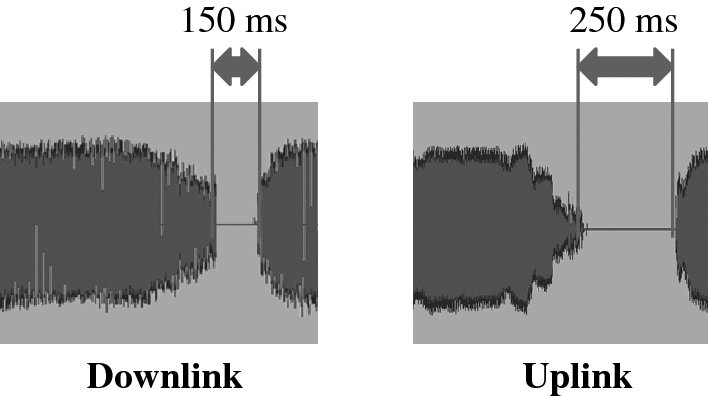
Figure 15.32 Voice interruption time in SRVCC
SRVCC was defined in Release 8 and further enhanced in the following releases:
- Release 8 defined SRVCC from LTE to WCDMA, GSM, and CDMA. SRVCC is also defined from HSPA to WCDMA and from HSPA to GSM for the case where VoIP is implemented in HSPA.
- Release 9 introduced SRVCC support for emergency calls that are anchored in the IMS core. It is not enough to have emergency call support for VoLTE, SRVCC functionality must also support emergency calls if there is a need to move from VoLTE to CS voice during emergency calls.
- Release 10 brings procedures for enhanced SRVCC (eSRVCC). Release 8 functionality requires that the home network is involved in SRVCC even if the procedure happens in the visited network. In order to avoid any unnecessary delays, eSRVCC was introduced to allow anchoring VoLTE within the visited network. In practice, LTE roaming even for data is currently in its very early phase (2014). When LTE data roaming agreements become more common, roaming cases may still use CS fallback even if VoLTE is used in the home network. eSRVCC also has the benefit that it hides SRVCC from the other operators in the case of inter-operator VoLTE – VoLTE call. Additionally, Release 9 also enables SRVCC in the alerting phase (aSRVCC).
- Release 11 enables two new capabilities: reverse SRVCC from CS voice back to VoLTE (rSRVCC) and SRVCC for video calls from LTE to CS video (vSRVCC). In the case of pre-Release 11, SRVCC was possible only from VoIP to CS voice, but not vice versa. Therefore, the voice call remained in the CS domain even if the UE returned to LTE coverage area. Release 11 allows movement of the call back to VoIP when LTE coverage becomes available again. The reverse SRVCC from 3G to LTE is controlled by RNC. Release 11 brings the relevant UE capability information to RNC to make RNC aware of UE VoIP capability.
15.6 Summary
3GPP has defined a comprehensive set of inter-working functions between LTE and 3G, both for data and for voice connections. The data connection can be transferred between LTE and 3G with reselection, redirection, and handovers. These features can be used for coverage, capacity, or service reason mobility between LTE and 3G. Most of the inter-working features need corresponding upgrades both in LTE and in 3G radio networks and core networks.
LTE and 3G voice inter-working relies initially on CS fallback where an LTE capable UE is moved to a 3G network for CS voice call. The simultaneous data connection can be handed over from LTE to 3G during a CS fallback procedure. 3GPP specifications in Release 8 also support the handover from VoLTE to CS voice in the 3G network called SRVCC with simultaneous packet data session continuity. SRVCC functionality is further enhanced in Releases 9, 10, and 11.
References
- 3GPP Technical Specifications 25.331 “Radio Resource Control (RRC); Protocol specification (UMTS)”, v. 8.7.0, 2009.
- 3GPP Technical Specifications 36.331 “Radio Resource Control (RRC); Protocol specification (LTE)”, v. 8.6.0, 2009.
- 3GPP Technical Specifications 25.133 “Requirements for support of radio resource management (UMTS)”, v. 8.8.0, 2009.
- 3GPP Technical Specifications 36.133 “Requirements for support of radio resource management (LTE)”, v. 8.8.0, 2009.
- 3GPP Technical Specifications 24.008 “Mobile radio interface Layer 3 specification”, v. 9.7.0, 2011.
- 3GPP Technical Specifications 24.301 “Non-Access-Stratum (NAS) protocol for Evolved Packet System (EPS)”, v. 9.7.0, 2011.
- 3GPP Technical Specifications 23.272 “Circuit Switched (CS) fallback in Evolved Packet System (EPS)”, v. 11.9.0, 2013.
- 3GPP Technical Specifications 24.278 “Service requirements for the Evolved Packet System (EPS)”, v. 8.9.0, 2011.
- 3GPP Technical Specifications 23.216 “Single Radio Voice Call Continuity (SRVCC)”, v. 11.9.0, 2013.