
Chapter 7
Mastering Viewing Tools, Hatches, and External References
Now that you’ve created drawings of a typical apartment unit and the apartment building’s lobby and stairs, you can assemble them to complete the first floor of the apartment building. In this chapter, you’ll take full advantage of the features of the AutoCAD® 2014 software to enhance your drawing skills as well as to reduce the time it takes to create accurate drawings.
As your drawing becomes larger, you’ll find that you need to use the Zoom and Pan commands more often. Larger drawings also require some special editing techniques. You’ll learn how to assemble and view drawings in ways that will save you time and effort as your design progresses. Along the way, you’ll see how you can enhance the appearance of your drawings by adding hatch patterns.
In this chapter, you will learn to:
- Assemble the parts
- Take control of the AutoCAD display
- Use hatch patterns in your drawings
- Understand the boundary hatch options
- Use external references
Assembling the Parts
One of the best timesaving features of AutoCAD is its ability to duplicate repetitive elements quickly in a drawing. In this section, you’ll assemble the drawings you’ve been working on into the complete floor plan of a fictitious apartment project. Doing so will demonstrate how you can quickly and accurately copy your existing drawings in a variety of ways.
Start by creating a new file for the first floor:
Now you’re ready to start building a floor plan of the first floor from the unit plan you created in the previous chapter. You’ll begin by creating a mirrored copy of the apartment plan:
If you happen to insert a block in the wrong coordinate location, you can use the Properties palette to change the insertion point for the block.
Continue the drawing by making mirrored copies of the inserted plan:
Figure 7-1 The unit plan mirrored
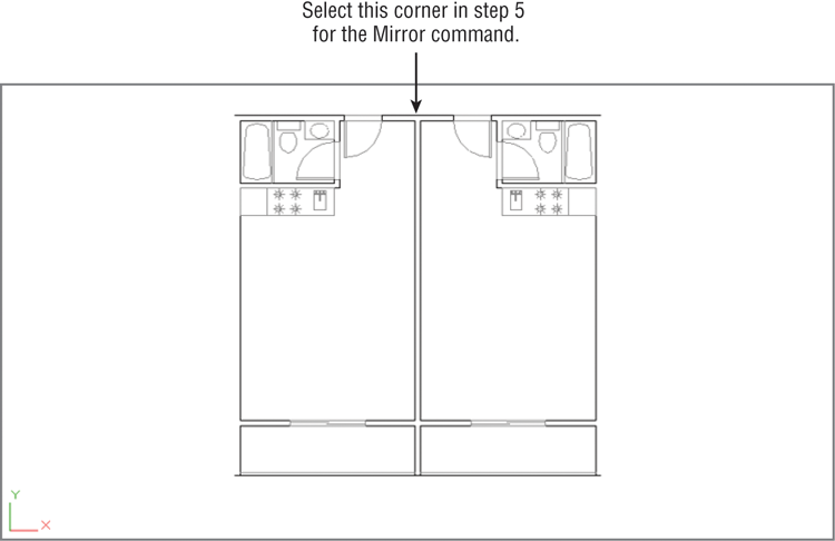
You now have a mirror-image copy of the original plan in the exact location required for the overall plan. Next, make some additional copies for the opposite side of the building:
With the tools you’ve learned about so far, you’ve quickly and accurately set up a fairly good portion of the floor plan. Continue with the next few steps to “rough in” the main components of the floor:
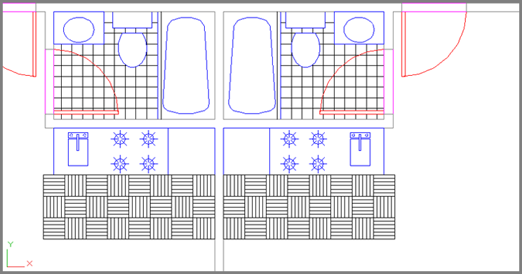
Figure 7-2 The unit plan, duplicated four times
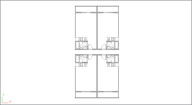
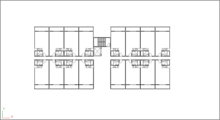
Figure 7-3 The Plan drawing
Taking Control of the AutoCAD Display
By now, you should be familiar with the Pan and Zoom functions in AutoCAD. Many other tools can also help you get around in your drawing. In the following sections, you’ll get a closer look at the ways you can view your drawing.
Understanding Regeneration and Redrawing
AutoCAD uses two commands for refreshing your drawing display: Regen (drawing regeneration) and Redraw. Each command serves a particular purpose, although it may not be clear to a new user.
To understand the difference between Regen and Redraw, it helps to know that AutoCAD stores drawing data in two ways:
- In a database of highly accurate coordinate information that is part of the properties of objects in your drawing
- In a simplified database used just for the display of the objects in your drawing
As you draw, AutoCAD starts to build an accurate, core database of objects and their properties. At the same time, it creates a simpler database that it uses just to display the drawing quickly. AutoCAD uses this second database to allow quick manipulation of the display of your drawing. For the purposes of this discussion, we’ll call this simplified database the virtual display because it’s like a computer model of the overall display of your drawing. This virtual display is, in turn, used as the basis for what is shown in the drawing area. When you issue a Redraw command, you’re telling AutoCAD to reread this virtual display data and display that information in the drawing area. A Regen command, on the other hand, tells AutoCAD to rebuild the virtual display based on information from the core drawing database.
You may notice that the Pan Realtime and Zoom Realtime commands don’t work beyond a certain area in the display. When you reach a point where these commands seem to stop working, you’ve come to the limits of the virtual display data. To go beyond these limits, AutoCAD must rebuild the virtual display data from the core data; in other words, it must regenerate the drawing. You can usually do this by zooming out to the extents of the drawing.
Sometimes, when you zoom in to a drawing, arcs and circles may appear to be faceted instead of smooth curves. This faceting is the result of the virtual display simplifying curves to conserve memory. You can force AutoCAD to display smoother curves by typing RE↵, which is the shortcut for the Regen command.
Saving Views
Another way to control your views is by saving them. You might think of saving views as a way of creating a bookmark or a placeholder in your drawing.
For example, a few walls in the Plan drawing aren’t complete. To add the lines, you’ll need to zoom into the areas that need work, but these areas are spread out over the drawing. AutoCAD lets you save views of the areas in which you want to work and then jump from one saved view to another saved view. This technique is especially helpful when you know you’ll often want to return to a specific area of your drawing.
You’ll see how to save and recall views in the following set of exercises. Here’s the first one:
Figure 7-4 The View Manager dialog box
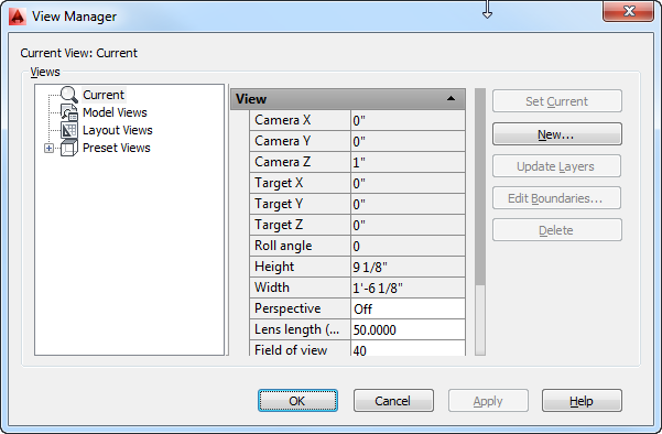
Figure 7-5 The New View / Shot Properties dialog box
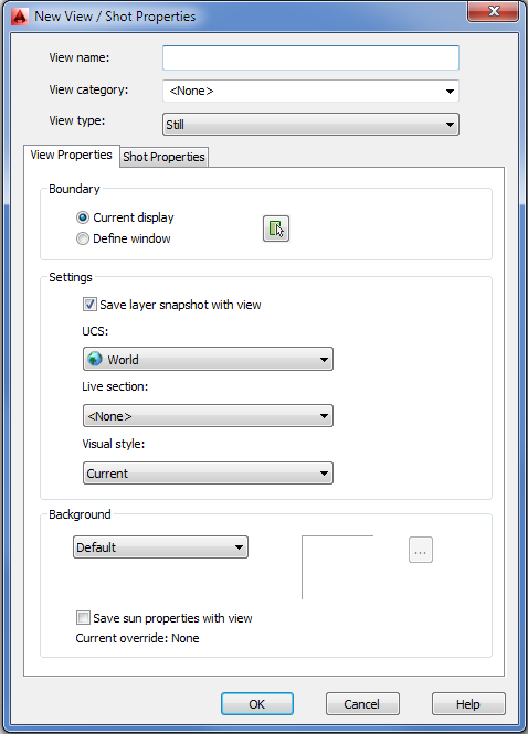
Figure 7-6 Select this area for your saved view.
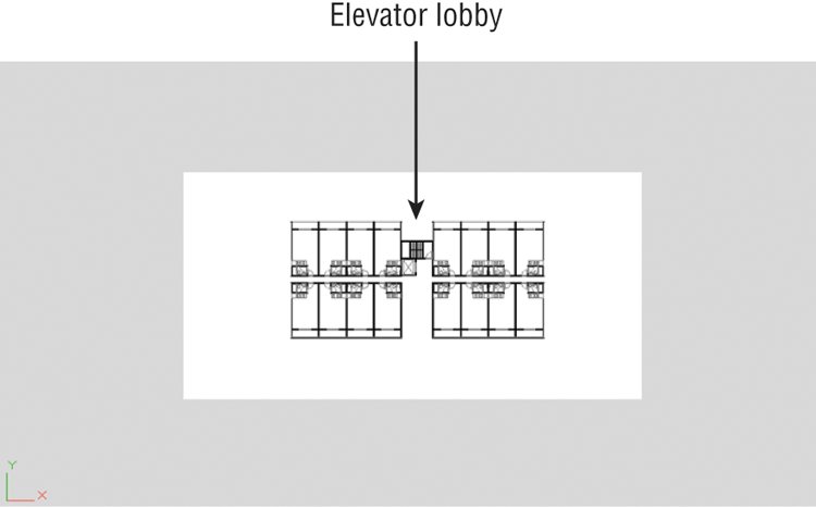
Your view changes to a close-up of the area you selected in step 4. You can also open the View Manager dialog box (enter V↵), select Elevator Lobby from the Views list, click Set Current, and click OK.
If you need to make adjustments to a view after you’ve created it, you can do so by following these steps: Right-click the view name in the View Manager dialog box, select Edit Boundaries, and then select a window as you did in steps 2 and 3.
If you prefer, you can use the keyboard to invoke the View command and thus avoid all the dialog boxes:
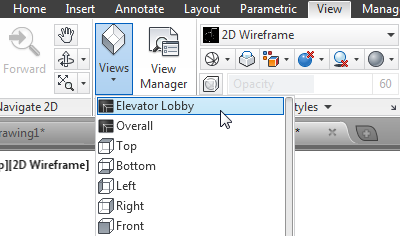
As you can see, this is a quick way to save a view. With the name Overall assigned to this view, you can easily recall it at any time. (Choosing the Zoom All flyout option from the Navigation bar gives you an overall view too, but it may zoom out too far for some purposes, or it may not show what you consider an overall view.)
Understanding the Frozen Layer Option
As mentioned earlier, you may want to turn off certain layers to plot a drawing containing only selected layers. But even when layers are turned off, AutoCAD still takes the time to redraw and regenerate them. The Layer Properties Manager offers the Freeze option; this acts like the Off option, except that Freeze causes AutoCAD to ignore frozen layers when redrawing and regenerating a drawing. By freezing layers that aren’t needed for reference or editing, you can reduce the time AutoCAD takes to perform regens. You’ll find this capability helpful when working with large files.
Be aware, however, that the Freeze option affects blocks in an unusual way. Try the following exercise to see firsthand how the Freeze option makes entire blocks disappear:
Figure 7-7 Freezing the Plan1 layer
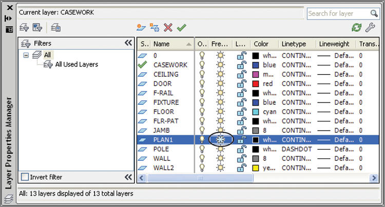
Even though none of the objects in the unit blocks were drawn on the Plan1 layer, the entire contents of the blocks assigned to the Plan1 layer are frozen when Plan1 is frozen. Another way to freeze and thaw individual layers is by clicking the Freeze/Thaw icon (which looks like a sun) in the layer drop-down list in the Home tab’s Layers panel.
You don’t really need the Plan1 layer frozen. You froze it to see the effects of Freeze on blocks. Do the following to turn Plan1 back on:
The previous exercise showed the effect of freezing on blocks. When a block’s layer is frozen, the entire block is made invisible regardless of the layer assignments of the objects contained in the block.
Keep in mind that when blocks are on layers that aren’t frozen, the individual objects that are part of the block are still affected by the status of the layer to which they’re assigned. This means that if some objects in a block are on a layer called Wall and the Wall layer is turned off or frozen, then those objects become invisible. Objects within the block that aren’t on the layer that is off or frozen remain visible.
Using Hatch Patterns in Your Drawings
To help communicate your ideas to others, you’ll want to add graphic elements that represent types of materials, special regions, or textures. AutoCAD provides hatch patterns for quickly placing a texture over an area of your drawing. In the following sections, you’ll add a hatch pattern to the floor of the studio apartment unit, thereby instantly enhancing the appearance of one drawing. In the process, you’ll learn how to update all the units in the overall floor plan quickly to reflect the changes in the unit.
Placing a Hatch Pattern in a Specific Area
It’s always a good idea to provide a separate layer for hatch patterns. By doing so, you can turn them off if you need to. For example, the floor paving pattern might be displayed in one drawing but turned off in another so it won’t distract from other information.
In the following exercises, you’ll set up a layer for a hatch pattern representing floor tile and then add that pattern to your drawing. This will give you the opportunity to learn the different methods of creating and controlling hatch patterns.
Follow these steps to set up the layer:
Now that you’ve set up the layer for the hatch pattern, you can place the pattern in the drawing:
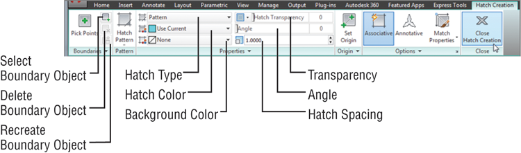
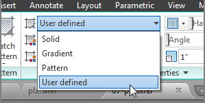
Figure 7-8 The Hatch Creation Ribbon tab
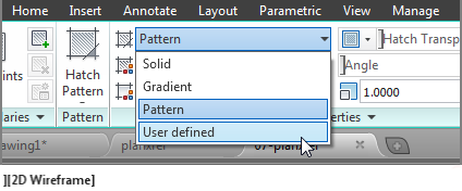
As you saw from the exercise, AutoCAD gives you a preview of your hatch pattern before you place it in the drawing. In the previous steps, you set up the hatch pattern first by selecting the User Defined option, but you can reverse the order if you like. You can click in the areas you want to hatch first and then select a pattern, adjust the scale, and apply other hatch options.
Adding Predefined Hatch Patterns
In the previous exercise, you used the User Defined option to create a simple crosshatch pattern. You also have a number of other predefined hatch patterns from which to choose. You can find other hatch patterns on the Internet, and if you can’t find the pattern you want, you can create your own (see Chapter 26, “Customizing Toolbars, Menus, Linetypes, and Hatch Patterns”).
Try the following exercise to see how you can add one of the predefined patterns available in AutoCAD:
Figure 7-9 The area below the kitchen, showing the outline of the floor tile area
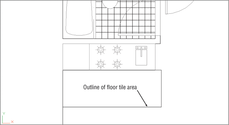
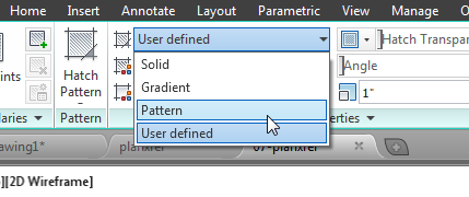
Figure 7-10 The Hatch Pattern flyout (left) and the Hatch Pattern panel in a full-screen AutoCAD window (right)

The predefined patterns with the AR prefix are architectural patterns that are drawn to full scale. In general, you should leave their Hatch Pattern Scale settings at 1. You can adjust the scale after you place the hatch pattern by using the Properties palette, as described later in this chapter.
Positioning Hatch Patterns Accurately
In the previous hatch pattern exercise, you may have noticed that the hatch pattern fits neatly into the 8f by 3f rectangle. The AR-PARQ1 pattern is made up of 1f squares, so they will fit exactly in an area that consists of even 1f increments. In addition, AutoCAD places the origin of the pattern in the bottom-left corner of the area being filled by default.
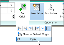
You won’t always have a hatch pattern fit so easily in an area. If you’ve ever laid tile in a bathroom, for example, you know that you have to select the starting point for your tiles carefully in order to get them to fit in an area with pleasing results. If you need to fine-tune the position of a hatch pattern within an enclosed area, you can do so by using the options in the Origin panel of the Hatch Creation tab.
The main tool in the panel, Set Origin, lets you select an origin point for your hatch pattern. You can also use the Hporigin system variable to accomplish this. Or you can expand the Origin panel for a set of predefined origin locations. These locations are Bottom Left, Bottom Right, Top Left, Top Right, Center, and Use Current Origin. The Use Current Origin option refers to the X,Y origin of the drawing.
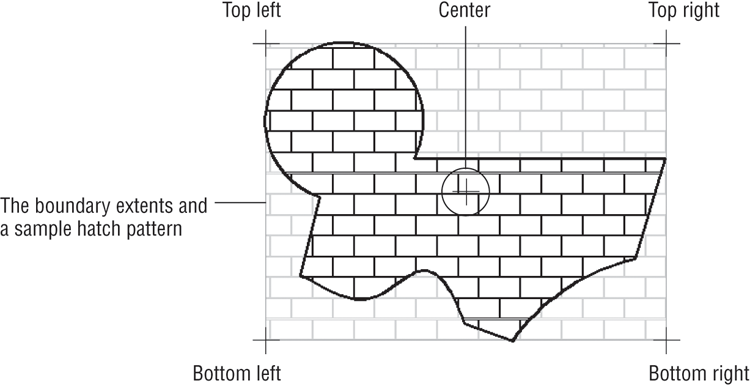
If you are hatching an irregular shape, these origin locations are applied to the boundary extents of the shape. An imaginary rectangle represents the outermost boundary, or the boundary extents of the shape, as shown in Figure 7-11.
Figure 7-11 The origin options shown in relation to the boundary extents of an irregular shape
The Store As Default Origin option lets you save your selected origin as the default origin for future hatch patterns in the current drawing.
Now that you’ve learned how to add a hatch pattern, let’s continue with a look at how your newly edited plan can be used. In the next exercise, you’ll use this updated 07a-unit file to update all the units in the Plan file.
Updating a Block from an External File
As you progress through a design project, you make countless revisions. With traditional drafting methods, revising a drawing, such as the studio apartment floor plan, takes a good deal of time. If you changed the bathroom layout, for example, you would have to erase every occurrence of the bathroom and redraw it 16 times. With AutoCAD, on the other hand, revising this drawing can be a quick operation. You can update the studio unit you just modified throughout the overall Plan drawing by replacing the current Unit block with the updated Unit file. AutoCAD can update all occurrences of the Unit block. The following exercise shows how this is accomplished.
For this exercise, remember that the blocks representing the units in the 07b-plan and 07b-plan-metric files are named 07a-unit and 07a-unit-metric:
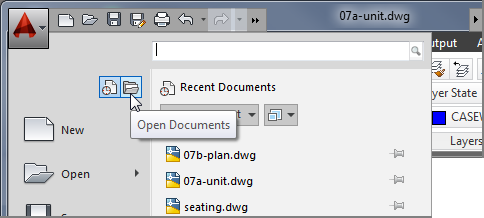
Figure 7-12 The Plan drawing with the tile pattern
Nested blocks must be updated independently of the parent block. For example, if you modified the Toilet block while editing the 07a-unit file and then updated the 07a-unit drawing in the 07b-plan file, the old Toilet block wouldn’t be updated. Even though the toilet is part of the 07a-unit file, it’s still a unique, independent block in the Plan file, and AutoCAD won’t modify it unless specifically instructed to do so. In this situation, you must edit the original Toilet block and then update it in both the Plan and Unit files.
Also, block references and layer settings of the current file take priority over those of the imported file. For example, if a file to be imported has layers of the same name as the layers in the current file but those layers have color and linetype assignments that are different from those in the current file, the current file’s layer color and linetype assignments determine those of the imported file. This doesn’t mean, however, that the imported file on disk is changed; only the insertion in the active drawing is affected.
Changing the Hatch Area
You may have noticed the Associative option in the Hatch Creation tab’s Options panel. When this option is turned on, AutoCAD creates an associative hatch pattern. Associative hatches adjust their shapes to any changes in their associated boundary, hence the name. The following exercise demonstrates how this works.
Suppose you want to enlarge the tiled area of the kitchen by one tile. Here’s how it’s done:
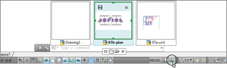
Figure 7-13 The Quick View Drawings tool
The Associative feature of hatch patterns can save time when you need to modify your drawing, but you need to be aware of its limitations. A hatch pattern can lose its associativity when you do any of the following:
- Erase or explode a hatch boundary
- Erase or explode a block that forms part of the boundary
- Move a hatch pattern away from its boundary
These situations frequently arise when you edit an unfamiliar drawing. Often, boundary objects are placed on a layer that is off or frozen, so the boundary objects aren’t visible. Also, the hatch pattern might be on a layer that is turned off and you proceed to edit the file not knowing that a hatch pattern exists. When you encounter such a file, take a moment to check for hatch boundaries so you can deal with them properly.
Modifying a Hatch Pattern
Like everything else in a project, a hatch pattern may eventually need to be changed in some way. Hatch patterns are like blocks in that they act like single objects. You can explode a hatch pattern to edit its individual lines. The Properties palette contains most of the settings you’ll need to make changes to your hatch patterns. But the most direct way to edit a hatch pattern is to use the Hatch Editor Ribbon tab.
Editing Hatch Patterns from the Hatch Editor Tab
Follow these steps to modify a hatch pattern by using the Hatch Editor Ribbon tab:
In this exercise, you were able to change the hatch just by clicking it. Although you changed only the pattern type, other options are available. You can, for example, modify a predefined pattern to a user-defined one by selecting User Defined from the Hatch Type drop-down list in the Properties panel of the Hatch Editor tab.
You can then enter angle and scale values for your hatch pattern in the options provided in the Properties panel of the Hatch Editor tab.
The other items in the Hatch Editor Ribbon tab are duplicates of the options in the Hatch Creation tab. They let you modify the individual properties of the selected hatch pattern. The upcoming section, “Understanding the Boundary Hatch Options,” describes these other properties in detail.
Editing Hatch Patterns from the Properties Palette
If you prefer, you can use the older method to edit a hatch pattern. To open the Properties palette, select and right-click the hatch pattern you want to edit and then select Properties. The Properties palette displays a Pattern category, which offers a Pattern Name option (see Figure 7-14).
Figure 7-14 The Pattern category in the Properties palette
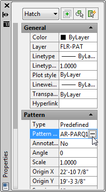
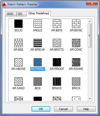
When you click this option, an ellipsis button appears, enabling you to open the Hatch Pattern Palette dialog box (see Figure 7-15). You can then select a new pattern from the dialog box. The Type option in the Properties palette lets you change the type of hatch pattern from Predefined to User Defined or Custom.
Figure 7-15 The Hatch Pattern Palette dialog box
Understanding the Boundary Hatch Options
The Hatch Creation and Hatch Editor Ribbon panels offer many other options that you didn’t explore in the previous exercises. For example, instead of clicking in the area to be hatched, you can select the objects that bound the area you want to hatch by clicking the Select Boundary Objects tool in the Boundaries panel. You can use the Select Boundary Objects tool to add boundaries to existing hatch patterns as well.
Controlling Boundaries with the Boundaries Panel
The previous exercises in this chapter have just touched on the tools in the Boundaries panel. Other options in the Boundaries panel are Pick Points, Select Boundary Objects, Remove Boundary Objects, and Recreate Boundary.
Fine-Tuning the Boundary Behavior
The Boundary Hatch feature is view dependent; that is, it locates boundaries based on what is visible in the current view. If the current view contains a lot of graphic data, AutoCAD can have difficulty finding a boundary or can be slow in finding a boundary. If you run into this problem, or if you want to single out a specific object for a point selection boundary, you can further limit the area that AutoCAD uses to locate hatch boundaries by using the Boundary Set options found in the expanded Boundaries panel:
The Boundary Set options are designed to give you more control over the way a point selection boundary is created. These options have no effect when you use the Select Boundary Objects button to select specific objects for the hatch boundary.
Controlling Hatch Behavior with the Options Panel
The Options panel offers a set of tools that control some additional features of the Hatch command. These features affect the way a hatch pattern fills a boundary area as well as how it behaves when the drawing is edited. Note that the Gap Tolerance, Create Separate Hatches, Normal Island Detection, and Send Behind Boundary options are on the expanded Options panel. The following gives you a brief description of each of the Options panel’s options:
Controlling Hatch Default Layer, Layout Scale, and ISO Line Weight
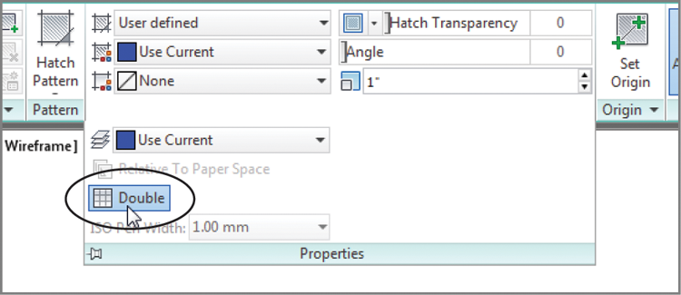
The expanded Properties panel contains a few items that you’ll want to be aware of as you become more familiar with AutoCAD. You’ve already seen how the Double option works when you are creating user-defined hatch patterns. The following describes several other options that are available:
Using Additional Hatch Features
The Hatch command has a fair amount of “intelligence.” As you saw in an earlier exercise, it was able to detect not only the outline of the floor area but also the outline of the toilet seat that represents an island in the pattern area. If you prefer, you can control how AutoCAD treats these island conditions and other situations by selecting options available in the Hatch Creation and Hatch Editor Ribbon tab. You also have the option to create and edit hatch patterns using the Hatch And Gradient dialog box (see Figure 7-16), which should be familiar to anyone who has used AutoCAD before.
Figure 7-16 The expanded Hatch And Gradient dialog box
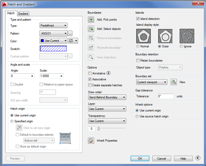
To open the Hatch And Gradient dialog box, start the Hatch command by clicking the Hatch tool in the Home tab’s Draw panel, and then click the Hatch Settings tool in the right side of the Options panel title bar. This opens the Hatch And Gradient dialog. Click the More Options button in the lower-right corner of this dialog box.
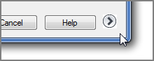
This button expands the dialog box to show additional hatch options (Figure 7-16).
Nearly all of the settings and tools in the Hatch And Gradient dialog box are repeated in the Hatch Creation and Hatch Editor Ribbon tabs. They are just presented in a different way.
Using Gradient Shading
You may have noticed Solid and Gradient options in the Pattern drop-down list. The solid hatch pattern lets you apply a solid color instead of a pattern to a bounded area. AutoCAD also offers a set of gradient patterns that let you apply a color gradient to an area.
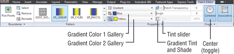
You can apply a gradient to an area using the same method you used to apply a hatch pattern, but when you select the Gradient option, you’ll see a slight change in the Hatch Creation tab panels. The Hatch Pattern Scale input box in the Properties panel changes to a Tint slider, and the Pattern panel changes to show a set of different gradient patterns. The Origin panel also changes to show Centered as the only option (see Figure 7-17). The Hatch Color and Background Color options in the Properties panel change to Gradient Color 1 and Gradient Color 2, enabling you to set the gradient colors.
Figure 7-17 The Gradient Shading feature
Choosing a Gradient Color
Instead of offering hatch patterns, the Pattern panel offers a variety of gradient patterns. If you don’t see the gradient patterns, you can click the Hatch Pattern tool to open a flyout of the gradient patterns. The Properties panel lets you control the colors of the gradient. You can select the colors from the two-color drop-down lists in the Properties panel.
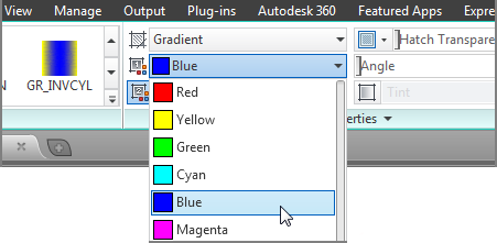
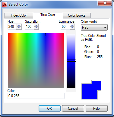
If you don’t see a color you want, you can click the Select Colors option at the bottom of the list to open the Select Color dialog box. This dialog box lets you choose from Index, True Color, or Color Books colors (see Figure 7-18).
Figure 7-18 The True Color options in the Select Color dialog box
The Gradient Tint And Shade slider just to the right of the color drop-down lists lets you control the shade of the single-color gradient.
Choosing Between a Single Color or Two Colors
You can choose a gradient that transitions between shades of a single color by clicking the Gradient Tint And Shade tool in the Properties panel just to the left of the Gradient Tint And Shade slider. This turns on the Gradient Tint And Shade slider and disables the Color 2 drop-down list. When you turn off the Gradient Tint And Shade button, the Gradient Tint slider is disabled and the Gradient Color 2 drop-down list is enabled.
Selecting Gradient Patterns
As mentioned earlier, you can choose from a set of gradient patterns in the Pattern panel. The Angle slider gives you further control over the gradient pattern by allowing you to rotate the angle of the pattern. The Centered option in the Origin panel places the center of the gradient at the center of the area selected for the pattern. This option is a toggle that is either on or off.
To place a gradient pattern, select a set of objects or a point in a bounded area, just as you would for a hatch pattern.
Tips for Using Hatch
Here are a few tips for using the Hatch feature:
- Watch out for boundary areas that are part of a large block. AutoCAD examines the entire block when defining boundaries. This can take time if the block is large. Use the Specify Boundary Set option to focus on the set of objects you want AutoCAD to use for your hatch boundary.
- The Hatch feature is view dependent; that is, it locates boundaries based on what is visible in the current view. To ensure that AutoCAD finds every detail, zoom into the area to be hatched.
- If the area to be hatched is large yet requires fine detail, first outline the hatch area by using a polyline. (See Chapter 19, “Drawing Curves,” for more on polylines.) Then use the Select Boundary Objects option in the Hatch Creation tab’s Boundaries panel to select the polyline boundary manually instead of depending on Hatch to find the boundary for you.
- Consider turning off layers that might interfere with the ability of AutoCAD to find a boundary.
- Hatch works on nested blocks as long as the nested block entities are parallel to the current CS.
Space Planning and Hatch Patterns
Suppose you’re working on a plan in which you’re constantly repositioning equipment and furniture, or you’re in the process of designing the floor covering. You might be a little hesitant to place a hatch pattern on the floor because you don’t want to have to rehatch the area each time you move a piece of equipment or change the flooring. You have two options in this situation: You can use the Hatch feature’s associative capabilities to include the furnishings in the boundary set, or you can use the Display Order feature.
Using Associative Hatch
Associative Hatch is the most straightforward method. Make sure the Associative option is selected in the Hatch Creation tab’s Options panel, and include your equipment or furniture in the boundary set. You can do this by using the Select option in the Boundaries panel.
After the pattern is in place, the hatch pattern automatically adjusts to its new location when you move the furnishings in your drawing. One drawback, however, is that AutoCAD attempts to hatch the interior of your furnishings if they cross the outer boundary of the hatch pattern. Also, if any boundary objects are erased or exploded, the hatch pattern no longer follows the location of your furnishings. To avoid these problems, you can use the method described in the next section, “Overlapping Objects with Draw Order.”
Overlapping Objects with Draw Order
The Draw Order feature lets you determine how objects overlap. In the space-planning example, you can create furniture by using a solid hatch to indicate horizontal surfaces (see Figure 7-19).
Figure 7-19 Using Draw Order to create an overlapping effect over a hatch pattern
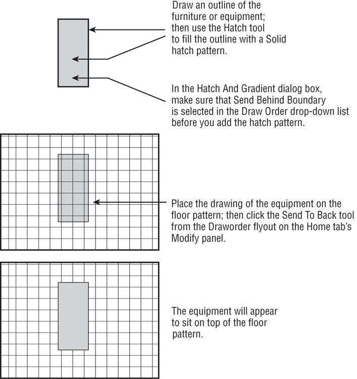
You can then place the furniture on top of a floor-covering pattern and the pattern will be covered and hidden by the furniture. Here’s how to do that. (These steps aren’t part of the regular exercises of this chapter. They’re shown here as general guidelines when you need to use the Draw Order feature.)
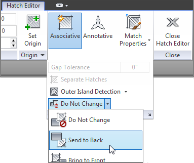
After you take these steps, the equipment will appear to rest on top of the pattern. (See the bottom panel in Figure 7-19.) You can also change the display order of objects relative to other objects in the drawing using the Draworder flyout in the Home tab’s Modify panel.
The Draworder options are all part of the Draworder command. As an alternative to using the Ribbon, you can type Draworder↵ at the Command prompt, select an object, and then enter an option at the prompt:
Enter object ordering option
[Above objects/Under objects/Front/Back] <Back>:
For example, the equivalent of choosing the Send To Back tool from the Draworder flyout is entering Draworder↵B↵. You can also select the object you want to edit, right-click, and then choose Draw Order from the context menu.
You’ve now had a detailed look at hatch patterns and fills. Remember that you can also use the tool palettes to help organize and simplify access to your favorite hatch patterns, or you can use the patterns already available in the tool palettes. The patterns in the tool palettes can be edited and manipulated in the same way as described in this chapter. If you want to know how to make full use of the tool palettes, check out the discussion on the AutoCAD DesignCenter™ in Chapter 27, “Managing and Sharing Your Drawings.”
Using External References
AutoCAD allows you to import drawings in a way that keeps the imported drawing independent from the current one. A drawing imported in this way is called an external reference (Xref). Unlike drawings that have been imported as blocks, Xref files don’t become part of the drawing’s database. Instead, they’re loaded along with the current file at startup time. It’s as if AutoCAD were opening several drawings at once: the currently active file you specify when you start AutoCAD and any file inserted as an Xref.
If you keep Xref files independent from the current file, any changes you make to the Xref automatically appear in the current file. You don’t have to update the Xref file manually as you do blocks. For example, if you use an Xref to insert the Unit file into the Plan file and you later make changes to the Unit file, you will see the new version of the Unit file in place of the old the next time you open the Plan file. If the Plan file was still open while edits were made, AutoCAD will notify you that a change has been made to an Xref.
Another advantage of Xref files is that, because they don’t become part of a drawing’s database, drawing size is kept to a minimum. This results in more efficient use of your hard disk space.
Xref files, like blocks, can be edited only by using special tools. You can, however, use osnaps to snap to a location in an Xref file, or you can freeze or turn off the Xref file’s insertion layer to make it invisible.
Attaching a Drawing as an External Reference
The next exercise shows how to use an Xref in place of an inserted block to construct the studio apartment building. You’ll first create a new unit file by copying the old one. Then you’ll bring a new feature, the External References palette, to the screen. Follow these steps to create the new file:
Now you’re ready to use the External References palette:
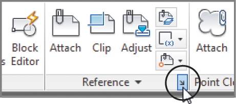
Figure 7-20 The External References palette
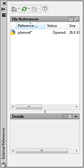
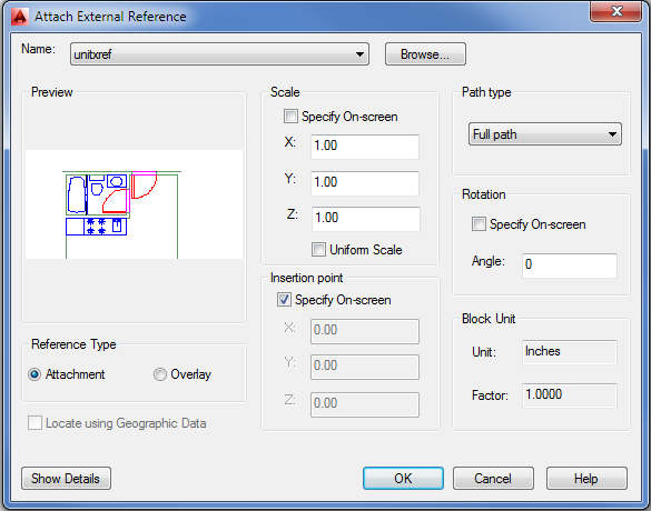
Figure 7-21 The Attach External Reference dialog box
You now have a drawing that looks like the 07b-plan.dwg file you worked with earlier in this chapter, but instead of blocks that are detached from their source file, you have a drawing composed of Xrefs. These Xrefs are the actual unitxref.dwg file, and they’re loaded into AutoCAD at the same time that you open the Planxref.dwg file. An icon in the lower-right corner of the AutoCAD window tells you that the current drawing contains Xrefs.
This icon not only alerts you to Xrefs, but it also enables you to open the External References palette, as you’ll see in the next exercise.
Next, you’ll modify the unitxref.dwg file and see the results in the Planxref.dwg file:
You may have noticed that there is a Reload DWG Xrefs option in the Manage Xrefs icon context menu. This option will reload all Xrefs in the current drawing without requiring you to select the individual file to reload in the External References palette.
Also, you may have noticed the Open option in step 4 when you used the right-click menu in the External References palette. This performs the same function as the Xopen command, which opens the selected Xref for editing.
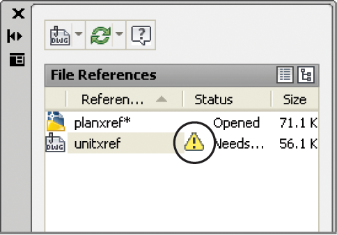
Be aware that when an Xref has been modified, the Manage Xrefs icon at the lower right in the AutoCAD window changes to show an exclamation point. This alerts you to changes in an Xref being used by the current drawing.
Click the Manage Xrefs icon to open the External References palette. The Xref that has been changed is indicated by a warning icon in the Status column of the list box along with the “Needs reloading” message.
You can then select the Xref that needs to be updated, right-click, and choose the Reload option from the context menu to reload the selected Xref. You can also select multiple Xrefs if more than one needs updating. Another option is to select Reload All References from the Refresh flyout at the top of the External References palette.
Here you saw how an Xref file is updated in a different way than a block. Because Xrefs are loaded along with the drawing file that contains them, the containing file, which in this case was the Planxref file, automatically displays any changes made to the Xref when it’s opened. Also, you avoid having to update nested blocks because AutoCAD updates nested Xrefs as well as non-nested Xrefs. When an Xref is modified while you’re editing a file, you’re alerted to the change through the Xref icon located in the lower-right corner of the AutoCAD window. You can click the balloon message that appears from that icon to update any modified Xrefs.
Other Differences Between External References and Blocks
Here are a few other differences between Xrefs and inserted blocks that you’ll want to keep in mind:
- Any new layers, text styles, or linetypes brought in with Xref files don’t become part of the current file. If you want to import any of these items, you can use the Xbind command (described in Chapter 15, “Advanced Editing and Organizing”).
- If you make changes to the layers of an Xref file, those changes aren’t retained when the file is saved unless you checked the Retain Changes To Xref Layers option in the Open And Save tab of the Options dialog box. This option, found in the External References (Xrefs) group, instructs AutoCAD to remember any layer color or visibility settings from one editing session to the next. In the standard AutoCAD settings, this option is on by default.
- Another way to ensure that layer settings for Xrefs are retained is to enter Visretain↵ at the Command prompt. At the New value for VISRETAIN <0>: prompt, enter 1.
- To segregate layers in Xref files from layers in the current drawing, AutoCAD prefixes the names of the Xref file’s layers with their file’s name. A vertical bar separates the filename prefix and the layer name when you view a list of layers in the layer drop-down list or the Layer Properties Manager dialog box (as in unitxref | wall).
- You can’t explode Xrefs. You can, however, convert an Xref into a block and then explode it. To do this, select the Xref in the External References palette, then right-click and choose Bind to open another dialog box that offers two ways of converting an Xref into a block. See the section “Other External Reference Options” later in this chapter for more information.
- If an Xref is renamed or moved to another location on your hard disk, AutoCAD won’t be able to find that file when it opens other files to which the Xref is attached. If this happens, you must select the path in the Found At field at the bottom of the External References palette and then click the Browse button (the ellipsis) to tell AutoCAD where to find the cross-referenced file.
- Take care when retargeting an Xref file with the Browse button. The Browse button can assign a file of a different name to an existing Xref as a substitution.
- Xref files are especially useful in workgroup environments in which several people are working on the same project. For example, one person might be updating several files that are inserted into a variety of other files. If blocks are used, everyone in the workgroup would have to be notified of the changes and would have to update all the affected blocks in all the drawings that contained them. With Xref files, however, the updating is automatic; you avoid confusion about which files need their blocks updated.
Other External Reference Options
Many other features are unique to external reference files. Let’s briefly look at some of the other options in the External References palette.
Options in the External References Palette
Several options are available when you right-click an external reference name listed in the External References palette, shown in Figure 7-20 earlier in this chapter. You saw the Reload option in an earlier exercise. The following other options are available:
Table 7-1: The Details panel of the External References palette
| Option | Function |
| Reference Name | Lets you give the Xref a name that is different from the Xref’s filename. This can be helpful if you want to use multiple external references of the same file. |
| Status | Tells you whether the Xref is loaded, unloaded, or not found (read only). |
| Size | Gives you the file size information (read only). |
| Type | Lets you choose between the Attach and Overlay attachment methods for the Xref file. Xrefs attached as overlays don’t include nested Xrefs. |
| Date | Gives you the date and time the file was attached (read only). |
| Saved Path | Tells you where AutoCAD expects to find the Xref file (read only). |
| Found At | Lets you select the location of the Xref file. When you click the text box for this option, a Browse button appears to the right. You can click this button to locate a lost Xref or use a different file from the original attached Xref. |
The Attach External Reference Dialog Box
The Attach External Reference dialog box, shown in Figure 7-21 earlier in this chapter, offers these options:
Clipping Xref Views and Improving Performance
Xrefs are frequently used to import large drawings for reference or backgrounds. Multiple Xrefs, such as a floor plan, column grid layout, and site-plan drawing, might be combined into one file. One drawback to multiple Xrefs in earlier versions of AutoCAD was that the entire Xref was loaded into memory even if only a small portion of it was used for the final plotted output. For computers with limited resources, multiple Xrefs could slow the system to a crawl.
AutoCAD offers two tools that help make display and memory use more efficient when using Xrefs: the Clip command and the Demand Load option in the Options dialog box.
Clipping Views
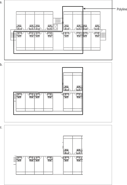
The Clip command, found in the Insert tab’s Reference panel, lets you clip the display of an Xref or a block to any shape you want, as shown in Figure 7-22. For example, you might want to display only an L-shaped portion of a floor plan to be part of your current drawing. Clip lets you define such a view. To access the command, choose Clip from the Insert tab’s Reference panel.
You can clip blocks and multiple Xrefs as well. You can also specify a front and back clipping distance so that the visibility of objects in 3D space can be controlled. You can define a clip area by using polylines or spline curves, although curve-fitted polylines revert to de-curved polylines. (See Chapter 19 for more on polylines and spline curves.)
Controlling Xref Settings in the Options Dialog Box
The External References (Xrefs) group in the Open And Save tab of the Options dialog box offers some tools to help you manage memory use and other features related to Xrefs. If you’re working on large projects with others in a workgroup, you should be aware of these settings and what they do.
The Demand Load Xrefs drop-down list offers three settings: Disabled, Enabled, and Enabled With Copy. Demand Load is set to Enabled With Copy by default in the standard AutoCAD setup. In addition to reducing the amount of memory an Xref consumes, Demand Load prevents other users from editing the Xref while it’s being viewed as part of your current drawing. This helps aid drawing version control and drawing management. The Enabled With Copy option creates a copy of the source Xref file and then uses the copy, thereby enabling other AutoCAD users to edit the source Xref file.
Demand loading improves performance by loading only the parts of the referenced drawing that are needed to regenerate the current drawing. You can set the location for the Xref copy in the Files tab of the Options dialog box under Temporary External Reference File Location.
Two other options are also available in the Options dialog box:
Figure 7-22 The first panel shows a polyline outline of the area to be isolated with the Clip option. The second panel shows how the Xref appears after Clip is applied. The last panel shows a view of the plan with the polyline’s layer turned off.
Editing Xrefs in Place
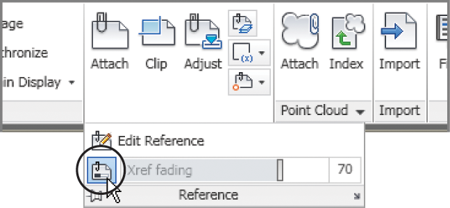
You’ve seen different methods for editing blocks and Xrefs as external files. There is also a way to edit a block or an Xref directly in a file without having to edit an external file: You can use the Edit Reference option in the Insert tab’s expanded Reference panel or the Edit Reference In-Place option in the External Reference tab’s Edit panel. These options issue the Refedit command.
The following exercise demonstrates how Refedit works:
Figure 7-23 The enlarged view of the unitxref in the Planxref file
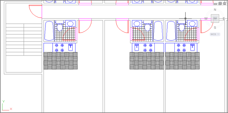
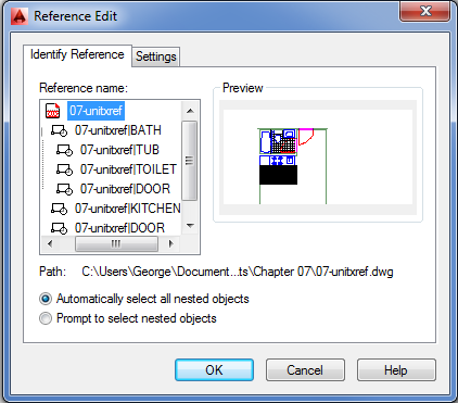
Figure 7-24 The Reference Edit dialog box
In step 5 of the previous exercise, the Refedit command isolates the objects you select for editing. You can’t edit anything else in the Xref until you exit the Refedit command and start over.
At this point, you can edit a block in an Xref. Now let’s continue editing the kitchenette:
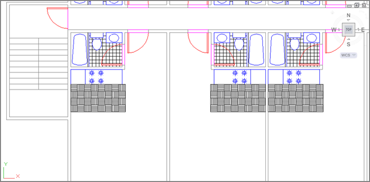
Figure 7-25 The Xrefs after being edited
As you saw from these two exercises, it’s possible to edit a specific block in an Xref, but to do that you must select the block name in the Reference Edit dialog box.
In these exercises, you edited a block contained in an Xref, but you could have just as easily edited a block in the current drawing. You can also edit nested blocks by using the Refedit command. Changes in blocks in the current file don’t affect other files because blocks aren’t linked to external files. The changes to blocks remain in the current file until you explicitly export the changed block to a file, as you saw in earlier exercises.
Using the External Reference Tab
Earlier, you saw that when you click an Xref, the External Reference tab appears. This tab offers several tools divided into three panels: Edit, Clipping, and Options. See Table 7-2 for a complete description of these tools.
Table 7-2: The External Reference tab options
| Tool Name | Function |
| Edit Reference In-Place | Starts the Refedit command, which allows you to edit an Xref within the current drawing. |
| Open Reference | Opens the selected Xref. |
| Create Clipping Boundary | Starts the Xclip command, which allows you to hide portions of an Xref. This feature is similar to the image clipping command described in Chapter 14, “Copying Existing Drawings from Other Sources.” |
| Removing Clipping | Removes a clipping boundary. |
| External References | Opens or closes the External References palette. |
Adding and Removing Objects from Blocks and Xrefs
In the previous exercises, you removed objects from the Kitchen block by using the Erase command. You can also move objects from a block or an Xref into the current drawing without erasing them. To do this, choose Remove From Working Set from the Edit Reference panel while in the Refedit command. This removes the objects from the block or Xref without erasing them. Likewise, you can add new objects to the block or Xref by choosing Add To Working Set from the Edit Reference panel. Both menu options invoke the Refset command, with different options applied. Also note that the Edit Reference panel appears in all the Ribbon tabs when you are in the Refedit command.
To see how Refset works, try the following exercise:
Figure 7-26 Moving the burners out of the Kitchen block and adding the rectangle
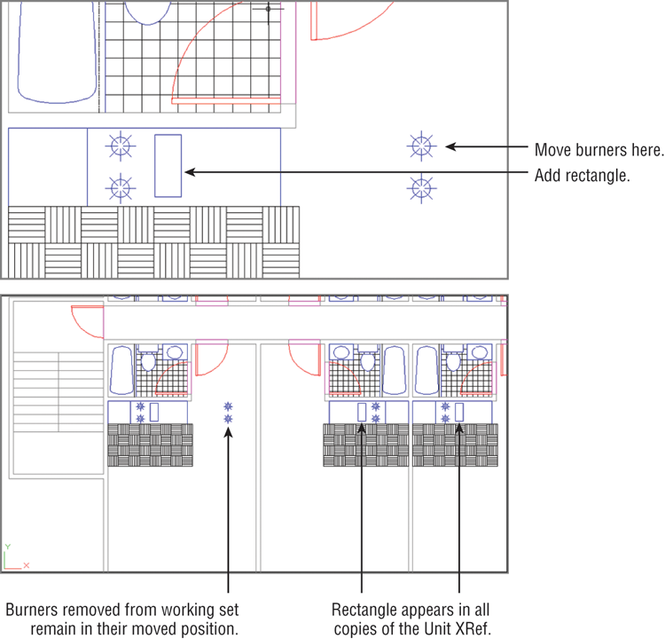
Notice that the burners become grayer to show that they’re removed from the working set. They remain as part of the Planxref drawing, but they’re no longer part of the Kitchen block.
Now add a rectangle to the Kitchen block in place of the burners:
Figure 7-27 The Planxref drawing with the changes made to the 07-unitxref Xref

You can see that the burners have been replaced by the rectangle in all the other Xref units. The burners you moved are still there in the lower-left corner unit, but they have been removed from all the Xrefs. It’s as if you extracted them from the block and placed them in the Plan drawing.
While you were using the Refedit command, any new objects you created were added to the working set automatically. When you drew the rectangle in step 1, for example, it was automatically included in the working set, which is the set of objects included in the block or Xref on which you’re currently working. You didn’t have to add it specifically to the working set.
If you want to include existing objects in the working set, choose the Add To Working Set tool from the Edit Reference panel.
You’ve completed the exercises in this chapter, so you can exit AutoCAD without saving these changes.
Understanding the Reference Edit Dialog Box Options
The Reference Edit dialog box offers you the option to isolate specific blocks in the Xref by selecting them from the hierarchy list. You may have noticed the two radio button options: Automatically Select All Nested Objects and Prompt To Select Nested Objects. The default option, Automatically Select All Nested Objects, lets you select any object contained in the selected object in the hierarchy listing. If you select the Prompt To Select Nested Objects option, you’re prompted to select objects on the screen before the Edit Reference panel appears.
In addition to the options you used in the exercises, the Reference Edit dialog box includes the Settings tab, which provides a few options (see Figure 7-28).
Figure 7-28 The Settings tab of the Reference Edit dialog box
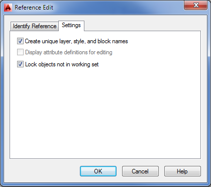
Create Unique Layer, Style, and Block Names
When you use the Refedit command with the Automatically Select All Nested Objects option turned on, you can import nested blocks into the current drawing. For example, if you selected the Bath block in the hierarchy list in the previous exercise, you would have access to the Tub and Toilet blocks in the Bath block. You could then copy either of those blocks into the current file.
When you make a copy of a block from an Xref, AutoCAD needs to assign that block a name. The Create Unique Layer, Style, And Block Names option tells AutoCAD to use the original block name and append a $#$ prefix to the name (# is a numeric value starting with 0). If you were to import the Bath block, for example, it would become $0$bath in the current drawing. This ensures that the block maintains a unique name when it’s imported, even if there is a block with the same name in the current drawing. If you turn off the Create Unique Layer, Style, And Block Names option, the original name is maintained. If the current drawing contains a block of the same name, the imported block uses the current file’s definition of that block.
Display Attribute Definitions for Editing
If your drawing contains attributes (see Chapter 13, “Using Attributes,” for more on attributes), this option is offered. If you turn on this option, you can then edit attribute definitions by using the Refedit command. If you select a block that contains an attribute definition while you’re using the Refedit command, the attribute definition is exposed, enabling you to make changes. Changes to attribute definitions affect only new attribute insertions. Except for the attribute of the edited block, existing attributes aren’t affected. If you want to update existing attributes to a newly edited definition, use the Sync option of the Block Attribute Manager (choose Manage Attributes from the Home tab’s expanded Block panel).
Lock Objects Not in Working Set
In the Refedit exercises, you saw that objects that aren’t selected in the Reference Edit dialog box are grayed out and aren’t selectable. The Lock Objects Not In Working Set option controls this feature and is turned on by default.