Chapter 10
Adding Text to Drawings
One of the more tedious drafting tasks is applying notes to your drawing. The AutoCAD® 2014 software makes this job faster by enabling you to type your notes, insert text from other sources, and copy notes that repeat throughout a drawing, and it helps you create professional-looking notes using a variety of fonts, type sizes, and type styles.
In this chapter, you’ll add notes to your apartment building plan. In the process, you’ll explore some of the AutoCAD text-creation and text-editing features. You’ll learn how to control the size, slant, type style, and orientation of text and how to import text files. You’ll start by working through some exercises that show you the process of preparing a drawing for text. You’ll then add a few lines of text to the drawing and learn how text size and drawing scale interrelate. The rest of the chapter shows you the tools available for formatting text to fit your application.
In this chapter, you will learn to:
- Prepare a drawing for text
- Set the annotation scale and add text
- Explore text formatting in AutoCAD
- Add simple single-line text objects
- Use the Check Spelling feature
- Find and replace text
Preparing a Drawing for Text
In these first sections, you’ll go through the process of adding text to a drawing that currently has none. By doing so, you’ll gain firsthand experience in using all the tools you’ll need for adding text to a drawing. Start by setting up a drawing to prepare it for the addition of text:
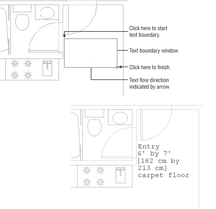
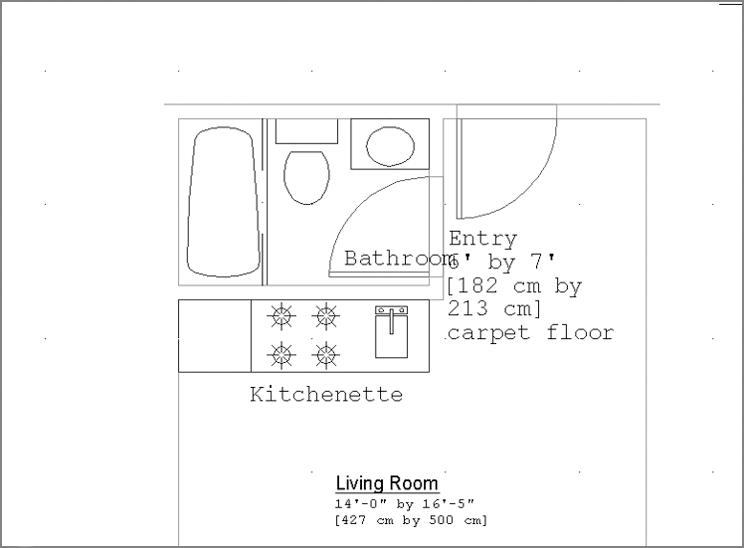
Figure 10-1 The top image shows the points to pick to place the text boundary window. The bottom image shows the completed text.
Organizing Text by Styles
Before you begin to add text to your drawing, you should set up a text style or two. You can think of text styles as a tool to store your most common text formatting. Styles store text height and font information so you don’t have to set these options every time you enter text. Generally, you’ll need only a few text styles.
Even if you started to add text without creating your own text style, you would still be using a text style. That’s because every text object must have a style, so AutoCAD includes the Standard text style in every new drawing. The Standard style uses an AutoCAD font called Txt and includes numerous other settings that you’ll learn about in this section. These other settings include width factor, oblique angle, and default height.
In this next exercise, you’ll create a text style called Note1, which you’ll use to add notes to the Unit plan on which you’ve been working:
Figure 10-2 The Text Style dialog box
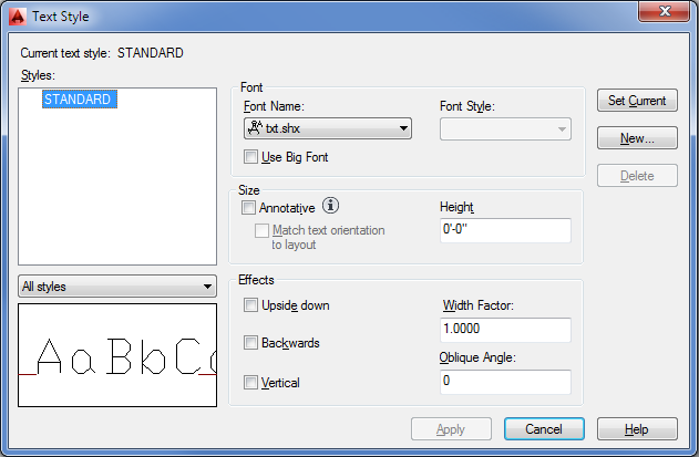
Figure 10-3 The Annotative option in the Text Style dialog box
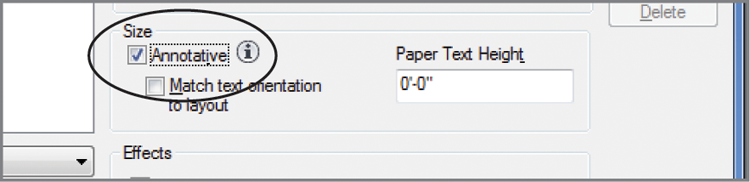
The Annotative option you turned on in step 6 is an important feature for keeping your text at the proper size for your drawing scale. You’ll see how it works in the exercises later in the section “Setting the Annotation Scale and Adding Text.”
Getting Familiar with the Text and Annotation Scale Control Panels
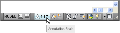
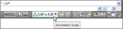
Before you get much further into the AutoCAD text features, take a moment to get familiar with the Annotate tab’s Text and Annotation Scaling panels (see Figure 10-4). You’ll be using a few of these panel tools in this chapter. If you need to, you can refer to this figure as you work through the exercises.
Figure 10-4 The Text panel (left) and the Annotation Scaling panel (right)
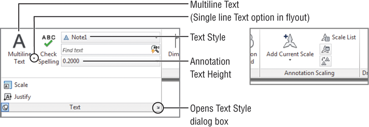
If your Annotation panel doesn’t look like the one in this figure, hover over it and the panel will expand to display the options.
Setting the Annotation Scale and Adding Text
You’ve got a text style set up and ready to use. Now you’ll add some text to your unit plan. Before you begin, you should determine a drawing scale. This is important because with the Annotative feature turned on, AutoCAD needs to know the drawing scale in order to set the size of the text. Follow these steps:
You’ve just set the drawing scale for the Model Space view. This isn’t a permanent setting; you can change it at any time, as you’ll see later. The settings you used for the annotation scale are somewhat arbitrary for the purposes of demonstrating the Annotative Scale feature.
Inserting Text
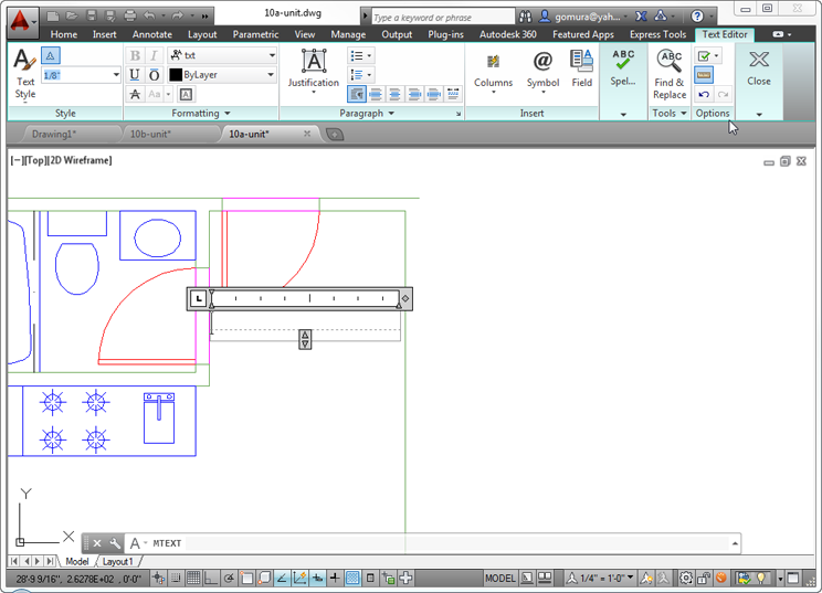
Finally, you can begin to add text. To start, you’ll add some text to label the entrance to the floor plan. The process is similar to the process in other graphics programs that offer a text feature. You draw a boundary in the area where you want the text to appear, and then you start typing:

Current text style: "Note1" Text height: 4 13/16"
Annotative: Yes
Specify first corner:Figure 10-5 The text editor floats over the selected area.

After you’ve added text, if the text doesn’t quite fit in the area you’ve indicated, you can make adjustments to the text boundary. Click the text to expose the text boundary, including the boundary grips. Then click and drag the grips to resize the boundary. The word-wrap feature automatically adjusts the text formatting to fit the text boundary.
You may have noticed that the Text Editor tab and text editor work like any text editor; if you make a typing error, you can highlight the error and retype the letter or word. You can perform other word-processing functions too, such as using search and replace, importing text, and changing fonts.
You also saw that the text editor shows how your text will appear in the location you selected using the text boundary. If your view of the drawing is such that the text is too small to be legible, the text editor enlarges the text so that you can read it clearly. Likewise, if you’re zoomed in too closely to see the entire text, the text editor adjusts the text to enable you to see all of it.
Exploring Text and Scale
Even though your text height is 0.1′, or 0.15 cm, it appears at the appropriately enlarged size for the current scale. If the text were drawn to the size of 0.1′, it would be very small and barely visible. However, the Annotative Scale feature makes the adjustment to your text size based on the Annotation Scale setting.
You can see how the Annotation Scale setting affects your text:
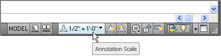
Figure 10-6 The Annotation Object Scale dialog box
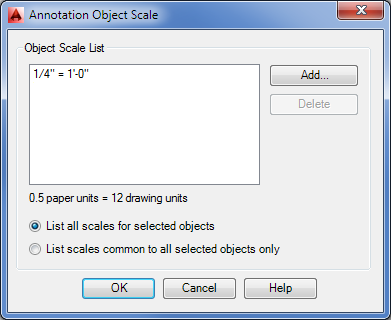
Figure 10-7 The Add Scales To Object dialog box
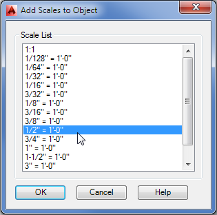
Now test your settings by changing the Annotation Scale value back to the previous setting:
In steps 2 through 4 of the first exercise in this section, you added a new annotation scale to the text. This is necessary for the text to be aware of the new annotation scale you want to use. Each time you include a new scale for your drawing, you need to add an annotation scale to the text in your drawing.
If you prefer, you can turn on the Automatically Add Scales To Annotative Objects tool in the status bar, which does just what its name says. The keyboard command for this tool is Annoautoscale↵4↵. Once a scale is added, you can quickly change between scales by selecting a scale from the Annotation Scale list.
So far, you’ve used only a single multiline text object. However, if you have many notes distributed throughout a drawing, you’ll need to add an annotation scale to all of them before they can automatically adjust themselves to the different scales you’ll use with your drawing. If you have the Automatically Add Scale To Annotative Objects tool turned on in the status bar, this happens automatically. Otherwise, you’ll have to add the scales to each annotative object. This is easy to do because you have the option to select as many objects as you need when adding annotation scales.
Understanding the Text Style Dialog Box Options
You’ve just taken nearly all the steps you’ll need to know to add text to any drawing. Now let’s take a step back and look more closely at some of the finer points of adding text, starting with text styles. The following sections give you more detailed information about the text style settings you saw in the early part of this chapter. They explain those settings and their purposes. Some of them, such as Width Factor, can be quite useful. Others, such as the Backwards and Vertical options, are rarely used. Take a moment to study these settings to become familiar with what is available and make a mental note of these items for future reference.
Styles
In the Styles list box, you’ll see a list showing the current style. This list also contains other styles that may be present in the drawing. The drop-down list below the Styles list box lets you control whether all styles are listed or just those that are being used in the drawing. In addition, there are the Set Current, New, and Delete buttons and options in the Font and Effects groups. You have already seen the Size group.
Set Current/New/Delete
Set Current makes the selected style the current one. New lets you create a new text style. Delete lets you delete the selected style.
The Delete option isn’t available for the Standard style.
Font
In the Font group, you have the following options:
Size
The Size group offers settings relating to text size, scale, and orientation.
Effects
In the Effects group, you have the following options:
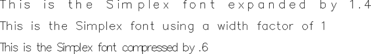
You can also set the width factor and oblique angle directly for text using the Width Factor and Oblique Angle tools in the expanded Formatting panel under the Text Editor Ribbon panel. This tab is available when you create new text or double-click existing text.
Exploring Text Formatting in AutoCAD
You’ve seen how you can set up a style and make scale adjustments. AutoCAD also offers a wide range of text-formatting options that are typical of the options in most word-processing programs. You can control fonts, text height, justification, line spacing, and width. You can even include special characters such as degree symbols or stacked fractions. With these additional formatting tools, you can make adjustments to the text style with which you started.
Adjusting the Text Height and Font
To get some experience using the text-formatting tools in AutoCAD, try the following exercise. You’ll use the Multiline Text tool again, but this time you’ll get to try out some of its other features.
In this exercise, you’ll see how you can use the Ribbon tools to adjust the size and font of text:
Figure 10-8 Placing the text-boundary window for the living-room label and the final label
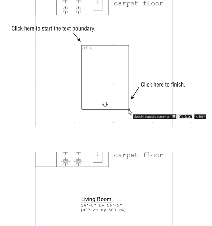

Living Room
14′-0″ by 16′-5″ [427 cm by 500 cm]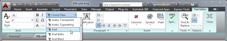

While using the Multiline Text tool, you may have noticed the [Height/Justify/Line spacing/Rotation/Style/Width/Columns]: prompt immediately after you picked the first point of the text boundary. You can use any of these options to make on-the-fly modifications to the height, justification, line spacing, rotation style, or width of the multiline text.
For example, after clicking the first point for the text boundary, you can typeR↵ and then specify a rotation angle for the text window, either graphically with a rubber-banding line or by entering an angle value. After you’ve entered a rotation angle, you can resume selecting the text boundary.
Understanding the Text Editor Tab
You’ve just experimented with a few of the Text Formatting features of the Text Editor tab. A variety of additional formatting tools are available. Figure 10-9 shows where these tools are, and Table 10-1 describes their uses. Note that Figure 10-9 shows the Ribbon with the AutoCAD window at a 1024-pixel width. The Style panel will display the text styles as a list in large displays. These Ribbon tools are fairly straightforward, and if you’ve used other word-processing programs, you should find them easy to use. Most are common to the majority of word processors, although a few—such as Symbol, Oblique Angle, and Width Factor—are unique to AutoCAD. Look at Table 10-1 and see if there are any tools you think you’ll find useful.
Figure 10-9 Additional features of the Text Editor tab
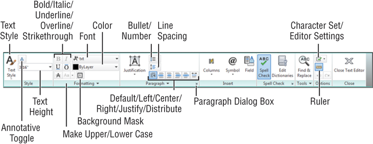
Table 10-1: Text formatting tools
| Tool | Use |
| Text Style (appears when the AutoCAD window is 1024 pixels wide or smaller) | Select a text style. |
| Annotative | Turn the Annotative feature on or off. |
| Text Height | Set the paper text height of text currently being entered or edited. |
| Bold/Italic/Underline/Overline/Strikethrough | Select text, and then select one of these options to add bold, italic, underline, overline, or strikethrough to the text. |
| Text Editor Color Gallery | Select text, and then choose a color from this drop-down list. |
| Font | Select a font different from the font for the current text style. |
| Background Mask | This tool gives you control over the background mask feature, which places a background behind text to make it more readable when placed over hatch patterns. |
| Make Lower/Upper Case | Change the case of text. |
| Line Spacing | Set the line spacing in paragraphs. You can also set line spacing in the Properties palette for an Mtext object or by using the Paragraph dialog box. (See “Setting Indents and Tabs” later in this chapter.) |
| Bullets And Numbering | Select a text list, click this tool, and then select Lettered, Numbered, or Bulleted to add letters, numbers, or bullets to the list. |
| Default/Left/Center/Right/Justify/Distribute | Click the appropriate tool to align the text to the left, center, or right side of the text boundary. Justify adds space between words to force left and right alignment. Distribute adds space between letters to force left and right alignment. |
| Paragraph | Paragraph opens a dialog box that lets you set up paragraph formatting, including tabs, indents, and paragraph spacing. |
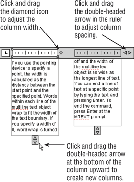
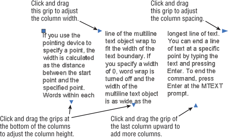
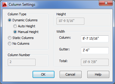
| Columns | Indicate the number of columns and how the columns are set up. |
| Symbol | Place the cursor at a location for the symbol, and then click the Symbol tool to find and add a symbol. (See Figure 10-10 later in this chapter for the available symbols.) |
| Field | Click to open the Field dialog box where you can add a text field. See “Adding Formulas to Cells” in Chapter 11, “Using Fields and Tables,” for more about fields. |
| Character Set/Editor Settings | Character Set offers foreign language characters such as Cyrillic or Greek, for example. Editor Settings offers settings for the text editor. |
| Ruler | Click to turn the ruler at the top of the Text panel on or off. |
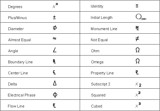
Adding Symbols and Special Characters
The Text Editor tab also offers a tool called Symbol. This tool lets you add special symbols common to technical drawing and drafting. Figure 10-10 shows the symbols that are offered in the Symbol tool in the form of a drop-down list.
Figure 10-10 Symbols available in AutoCAD
At the bottom of the Symbol drop-down list is an option called Other. By clicking the Other option, you open the Windows Character Map dialog box (see Figure 10-11). Characters such as the trademark (™) and copyright (©) symbols are often available in the fonts offered in the Character Map. The contents of the Character Map depend on the font currently selected.
Figure 10-11 The Character Map
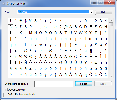
The Character Map is a Windows accessory. If it doesn’t appear when you choose Other from the Symbol tool menu, you may need to install the Character Map from your Windows installation CD.
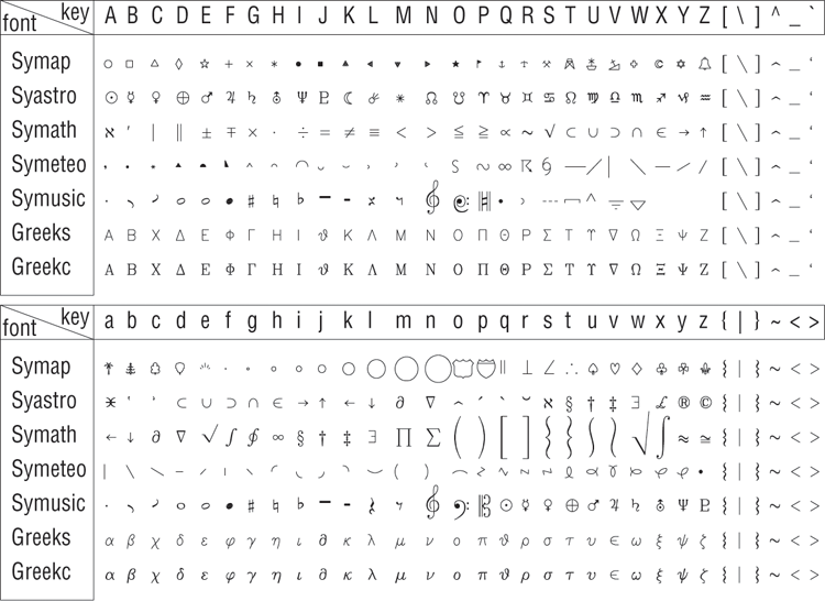
Finally, if your application requires music, math, astronomy, Greek, or other symbols, AutoCAD offers a set of fonts with special symbols. Figure 10-17, later in the chapter, shows these fonts and the symbols they contain. You can set up text styles with these fonts or call them up directly from the Formatting panel’s Font option.
Text Justification and Osnaps
You may have noticed that the object-justification list offers three center options: Top Center, Middle Center, and Bottom Center. All three of these options have the same effect on the text’s appearance, but they each have a different effect on how osnaps act on the text. Figure 10-12 shows where the osnap point occurs on a text boundary depending on which justification option is selected. A multiline text object has only one insertion point on its boundary, which you can access with the Insert osnap.
Figure 10-12 The location of the Insert osnap point on a text boundary, based on its justification setting
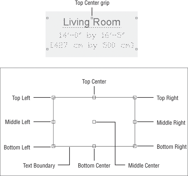
The osnap point also appears as an extra grip point on the text boundary when you click the text. If you click the text you just entered, you’ll see that a grip point now appears at the top center of the text boundary.
Knowing where the osnap points occur can be helpful when you want to align the text with other objects in your drawing. In most cases, you can use the grips to align your text boundary, but the Top Center and Middle Center justification options enable you to use the center and middle portions of your text to align the text with other objects.
Changing Justification of Multiple Text Objects
You’ve seen how you can change the justification of an individual text object, but you’ll often find that you need to change the justification of several text objects at one time. AutoCAD offers the Justifytext command for this purpose. To use it, click the Justify tool in the Annotate tab’s expanded Text panel, or type Justifytext↵ at the Command prompt. At the Select objects: prompt, select the text you want to change and then press ↵ to confirm your selection. You’ll see the following prompt in the command line (or at the cursor if Dynamic Input is on):
[Left/Align/Fit/Center/Middle/Right/TL/TC/TR/ML/MC/MR/BL/BC/BR] <Left>:Enter the letters corresponding to the type of justification you want to use for the text. (See the section “Justifying Single-Line Text Objects”later in this chapter for a description of these options.) After you enter an option, the selected text changes to conform to the selected justification option.
Setting Indents and Tabs
You should also know about the indent and tab features of the text editor. You may have noticed the ruler at the top of the text editor. Figure 10-13 shows that ruler, including tabs and indent markers.
Figure 10-13 The ruler at the top of the text editor lets you quickly set tabs and indents for text.
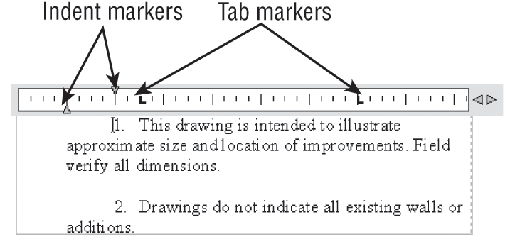
The indent markers let you control the indention of the first line and the rest of the paragraph. The tab markers give you control over tab spacing. For new text, the tab markers don’t appear until you add them by clicking the ruler. The following exercises will demonstrate the use of these markers.
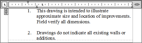
Start by practicing with the indent markers:

Here you see how you can control the indents of the selected text with the indent markers. You can set paragraphs of a single Mtext object differently, giving you a wide range of indent-formatting possibilities. Just select the text you want to set, and then adjust the indent markers.
Now try the tab markers. For this exercise, you’ll try the text-import feature to import a tab-delimited text file:

The file you just imported was generated from the Attribute Extraction Wizard in AutoCAD. You’ll learn more about this feature in Chapter 13, “Using Attributes.” This file contains tabs to align the columns of information. You can adjust those tabs in the Text Formatting toolbar, as you’ll see in the next set of steps.
Now use the tab markers to adjust the tab spacing of the columns of text:
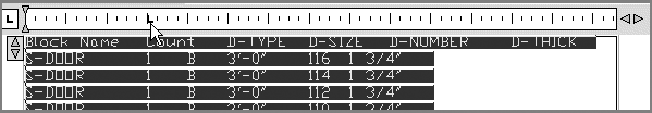
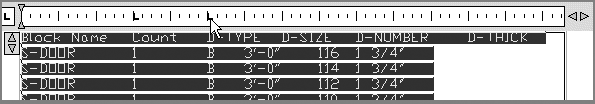
Figure 10-14 Add tab markers so your text looks similar to this figure.
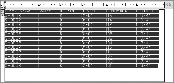
Here you saw how you can create a table or a schedule from an imported text file. You can also create a schedule from scratch by composing it directly in the text editor of the Multiline Text command. AutoCAD also offers the Table feature, which is specifically designed for creating tables (see Chapter 11). Still, the previous example offers a way to demonstrate the tab feature in the Multiline Text tool, and you may encounter a file in which a table is formatted in the way described here.
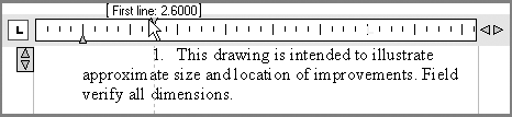
In addition to using the indent and tab markers on the ruler, you can control indents and tabs through the Paragraph dialog box. Do the following to get a firsthand look:
Figure 10-15 The Paragraph dialog box
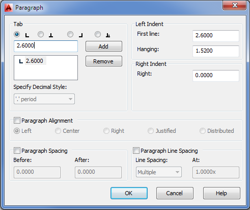
In this exercise, you used the Paragraph dialog box to set the paragraph indent and the first tab marker to be the same value. This causes the text portion of the list to be aligned at a distance of 2.2 drawing units from the left text boundary, leaving the list number extended farther to the left. This gives the list a more professional appearance.
The Paragraph dialog box gives you fine control over the formatting of your text. It lets you delete tabs by highlighting them in the list and clicking the Remove button. You can also add tabs at specific distances from the left margin of the text boundary by entering new tab locations in the Tab box and clicking the Add button.
You specify distances in drawing units. If your drawing is set up to use architectural units, for example, you can enter values in feet and inches or just inches. In the First Line and Hanging boxes, you enter a numeric value for paragraph indents. As you’ve just seen, you can use the First Line and Hanging boxes to create a numbered list by setting the Hanging box value to be the same as the first tab stop position.
What Do the Fonts Look Like?
You’ve already seen a few of the fonts available in AutoCAD. Chances are that you’re familiar with the TrueType fonts available in Windows. You have some additional AutoCAD fonts from which to choose. You may want to stick with the AutoCAD fonts for all but your presentation drawings because other fonts can consume more memory.
Figure 10-16 shows the basic AutoCAD text fonts. The Romans font is perhaps the most widely used because it offers a reasonable appearance while consuming little memory. Figure 10-17 lists some of the symbols and Greek fonts.
Figure 10-16 Some of the standard AutoCAD text fonts

Figure 10-17 Some of the AutoCAD symbols and Greek fonts
In the following sections, you’ll work with some of the AutoCAD fonts. You can see samples of all the fonts, including TrueType fonts, in the preview window of the Text Style dialog box. If you use a word processor, you’re probably familiar with at least some of the TrueType fonts available in Windows and AutoCAD.
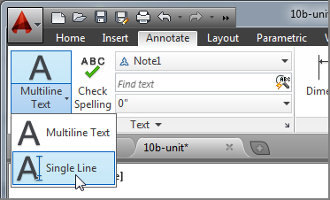
Adding Simple Single-Line Text Objects
You might find that you’re entering a lot of single words or simple labels that don’t require all the bells and whistles of the multiline text editor. AutoCAD offers the single-line text object, which is simpler to use and can speed text entry if you’re adding only small pieces of text.
Continue the tutorial on the Unit.dwg or the 10b-unit.dwg sample file by trying the following exercise:
Figure 10-18 Adding simple labels to the kitchen and bath by using the Text command
Here you were able to add two single lines of text in different parts of your drawing fairly quickly. Text uses the current default text style settings. If you want to create a column of single-line text, you can press ↵ to move the cursor down to start a new line below the one you just entered.
To edit single-line text, you can double-click the text. The text is highlighted, and you can begin typing to replace it all, or you can click a location in the text to make single word or character changes.
This is the end of the tutorial section of this chapter. The rest of this chapter offers additional information about text.
Justifying Single-Line Text Objects
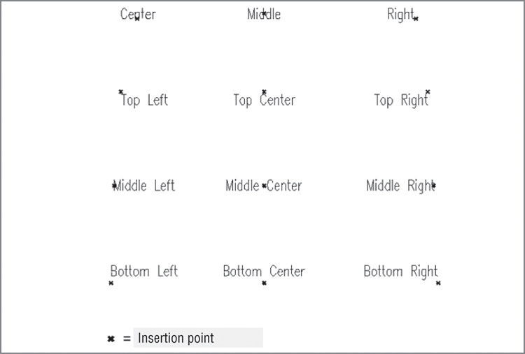
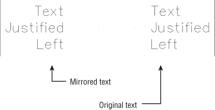
Justifying single-line text objects is slightly different than justifying multiline text. For example, if you change the justification setting to Center, the text moves so that the center is placed at the text-insertion point. In other words, the insertion point stays in place while the text location adjusts to the new justification setting. Figure 10-19 shows the relationship between single-line text and the insertion point based on different justification settings.
Figure 10-19 Text inserted using the various justification options
To set the justification of text as you enter it, you must enter J↵ at the Specify start point of text or [Justify/Style]: prompt after issuing the Text command. You can also change the current default style by entering S↵ and then the name of the style at the Specify start point of text or [Justify/Style]: prompt.
After you’ve issued Text’s Justify option, you get the following prompt:
Enter an option
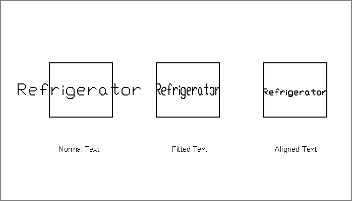
[Align/Fit/Center/Middle/Right/TL/TC/TR/ML/MC/MR/BL/BC/BR]:Here are descriptions of each of these options. (We’ve left Fit and Align until last because they require more explanation.)
Figure 10-20 The word Refrigerator as it appears normally and with the Fit and Align options selected
You can change the justification of single-line text by using the Properties palette, but the text moves from its original location while maintaining its insertion point. If you want to change the justification of text without moving the text, you can use the Justifytext command. Click the Justify tool in the Annotate tab’s expanded Text panel, or type Justifytext at the Command prompt, and then select the text you want to change. Justifytext works on both multiline and single-line text.
Using Special Characters with Single-Line Text Objects
Just as with multiline text, you can add a limited set of special characters to single-line text objects. For example, you can place the degree symbol (°) after a number, or you can underscore (underline) text. To accomplish this, you use double percent signs (%%) in conjunction with a special code. For example, to underscore text, you enclose that text with %% followed by the letter u, which is the underscore code. So to create the text “This is underscored text,” you enter the following at the prompt:
This is %%uunderscored%%u text.Overscoring (putting a line above the text) operates in the same manner. To insert codes for symbols, you place the codes in the correct positions for the symbols they represent. For example, to enter 100.5°, you type 100.5%%d. Table 10-2 shows some other examples of special character codes.
Table 10-2: Special character codes
| Code | What it does |
| %%o | Toggles overscore on and off. |
| %%u | Toggles underscore on and off. |
| %%c | Places a diameter symbol where the code occurs. |
| %%d | Places a degree sign (°) where the code occurs. |
| %%p | Places a plus/minus sign where the code occurs. |
| %%% | Forces a single percent sign. This is useful when you want a percent sign in conjunction with another code. |
| %%nnn | Allows the use of extended characters or Unicode characters when these characters are available for a given font. nnn is the three-digit value representing the ASCII extended character code. |
Using the Character Map Dialog Box to Add Special Characters
You can add special characters to a single line of text in the same way you add special characters to multiline text. You may recall that to access special characters, you use the Character Map dialog box.
To open the Character Map dialog box, choose Start ⇒ All Programs ⇒ Accessories ⇒ System Tools ⇒ Character Map. You can then use the procedure discussed in the section “Adding Symbols and Special Characters” earlier in this chapter to cut and paste a character from the Character Map dialog box. If you use the Character Map dialog box often, create a shortcut for it and place the shortcut in your Start menu or on your Desktop.
Using the Check Spelling Feature
Although AutoCAD is primarily a drawing program, you’ll find that some of your drawings contain more text than graphics, and so AutoCAD does include a spell checking tool. If you’ve ever used the spelling checker in a typical word processor, such as Microsoft Word, the operation in AutoCAD will be familiar to you.
How Check Spelling Works
The hardest part to using the Check Spelling tool is locating it in the Ribbon. Try the following to see how it works:
Figure 10-21 The Check Spelling dialog box
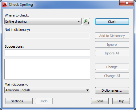
When the spelling checker finds a word it doesn’t recognize, the Check Spelling dialog box shows you the word along with a suggested spelling. If the spelling checker finds more than one spelling, a list of suggested alternate words appears below the box. You can then highlight the desired replacement and click the Change button to change the misspelled word, or you can click Change All to change all occurrences of the word in the selected text. If the suggested word is inappropriate, choose another word from the replacement list (if any) or enter your own spelling in the Suggestions box. Then click Change or Change All.
Here is a list of the options available in the Check Spelling dialog box:
The Check Spelling feature includes types of notations that are more likely to be found in technical drawings. It also checks the spelling of text that is included in block definitions, externally referenced files, and dimensions.
Choosing a Dictionary
Clicking the Dictionaries button in the Check Spelling dialog box opens the Dictionaries dialog box (see Figure 10-22), where you can select a particular main dictionary for foreign languages or create or choose a custom dictionary. The names of main dictionary files have the .dct extension. The main dictionary for the US version of AutoCAD is Enu.dct.
Figure 10-22 Choosing a dictionary
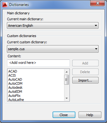
In the Dictionaries dialog box, you can also add or delete words from a custom dictionary. Custom dictionary files are ASCII files with names that end with the .cus extension. Because they’re ASCII files, you can edit them outside of AutoCAD. Click the Current Custom Dictionary drop-down list to view a list of existing custom dictionaries.
If you prefer, you can select a main or custom dictionary by using the Dctmain system variable. Click the Help button and then, in the Autodesk® Exchange window, select the Search tab. Enter Dctmain to learn more about the Dctmain system variable.
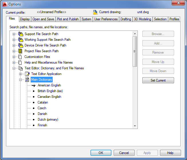
You can also select a dictionary from the Files tab of the Options dialog box (see Figure 10-23; choose Options from the Application menu). You can find the dictionary list under Text Editor, Dictionary, And Font File Names. Click the plus sign next to this item, and then click the plus sign next to the Main Dictionary item to display the dictionary options. From here, you can double-click the dictionary you prefer.
Figure 10-23 Choosing a dictionary via the Options dialog box
Substituting Fonts
At times, you’ll want to change all the fonts in a drawing quickly. For instance, you might need to convert the font of a drawing received from another office to a font that conforms to your own office standards. The Fontmap system variable works in conjunction with a font-mapping table, enabling you to substitute fonts in a drawing easily.
The font-mapping table is an ASCII file called Acad.fmp, which is located in the C:UsersUser NameAppDataRoamingAutodeskAutoCAD 2014R19.1enuSupport folder. You can also use a file you create yourself. You can give this file any name you choose, as long as it has the .fmp extension.
This font-mapping table contains one line for each font substitution you want AutoCAD to make. A typical line in this file reads as follows:
romant; C:Program FilesAutodeskAutoCAD 2014Fonts xt.shxIn this example, AutoCAD is directed to use the txt.shx font in place of the romant.shx font. To execute this substitution, you type Fontmap↵Fontmap_filename↵.
Fontmap_filename is the font-mapping table you created. This tells AutoCAD where to look for the font-mapping information. Then you issue the Regen command to view the font changes. To disable the font-mapping table, type Fontmap↵.
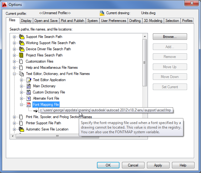
You can also specify a font-mapping file in the Files tab of the Options dialog box. Look for the Text Editor, Dictionary, And Font File Names listing. Click the plus sign next to this listing, and then click the plus sign next to the Font Mapping File listing to display the name and location of the current default font-mapping file. If you hold the cursor over the name, AutoCAD displays the full location of the file (see Figure 10-24).
You can double-click this filename to open the Select A File dialog box. From there, you can select a different font-mapping file.
Figure 10-24 AutoCAD shows the full path to the font-mapping file.
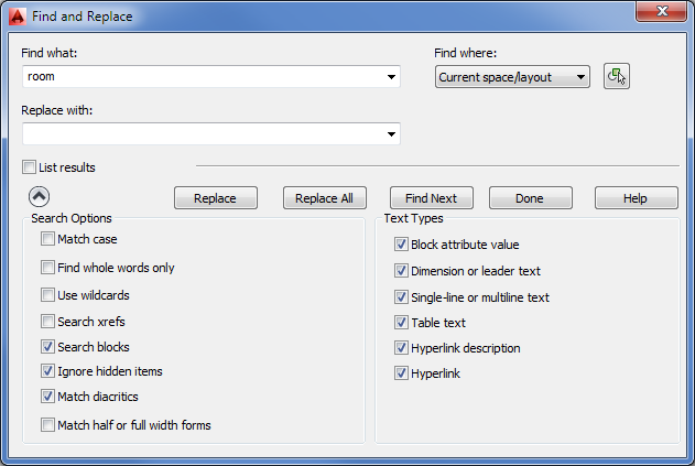
Finding and Replacing Text
One of the most time-consuming tasks in drafting is replacing text that appears repeatedly throughout a drawing. Fortunately, you have a Find And Replace tool to help simplify this task. Find And Replace in AutoCAD works like any other find-and-replace tool in a word-processing program. A few options work specifically with AutoCAD. Here’s how it works:
Figure 10-25 Using Find And Replace
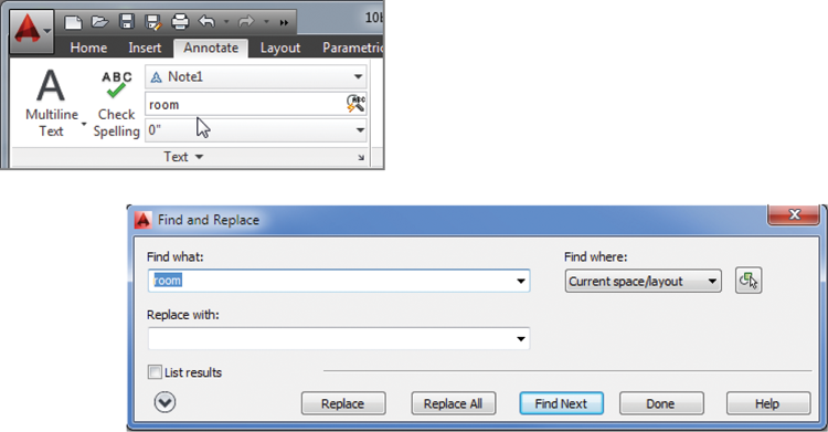
You can also enter Find↵ at the Command prompt to open the Find And Replace dialog box and then enter the text you want in the Find What text box.
You can also limit your find-and-replace operation to a specific set of objects in your drawing by choosing Selected Objects from the Find Where drop-down list. Once you’ve selected this option, click the Select Objects tool in the upper-right corner of the Find And Replace dialog box (see Figure 10-26).
Figure 10-26 The Select Objects tool
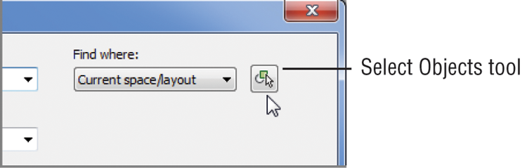
When you click the Select Objects tool, the Find And Replace dialog box closes temporarily to enable you to select a set of objects or a region of your drawing. Find And Replace then limits its search to those objects or the region you select.
You can further control the types of objects that Find And Replace looks for by clicking the More Options tool in the lower-left corner of the Find And Replace dialog box. The dialog box expands to show more options (see Figure 10-27).
With this dialog box, you can refine your search by limiting it to blocks, dimension text, standard text, or hyperlink text. You can also specify whether to match the case and find whole words only.
Figure 10-27 More extensive options for Find And Replace