Chapter 12
Using Dimensions
Before you determine the dimensions of a project, your design is in flux and many questions may be unanswered. After you begin dimensioning, you’ll start to see whether things fit or work together. Dimensioning can be crucial to how well a design works and how quickly it develops. The dimensions answer questions about code conformance if you’re an architect; they answer questions about tolerances, fit, and interference if you’re involved in mechanical applications. After you and your design team reach a design on a schematic level, communicating even tentative dimensions to others on the team can accelerate design development. Dimensions represent a point from which you can develop your ideas further.
With the AutoCAD® 2014 software, you can easily add tentative or final dimensions to any drawing. AutoCAD gives you an accurate dimension without your having to take measurements. You pick the two points to be dimensioned and the dimension line location, and AutoCAD does the rest. The associative dimensioning capability of AutoCAD automatically updates dimensions whenever the size or shape of the dimensioned object changes. These dimensioning features can save you valuable time and reduce the number of dimensional errors in your drawings.
In this chapter, you will learn to:
- Understand the components of a dimension
- Create a dimension style
- Draw linear dimensions
- Edit dimensions
- Dimension nonorthogonal objects
- Add a note with a leader arrow
- Apply ordinate dimensions
- Add tolerance notation
Understanding the Components of a Dimension
Before you start the exercises in this chapter, it will help to know the names of the parts of a dimension. Figure 12-1 shows a sample of a dimension with the parts labeled. The dimension line is the line that represents the distance being dimensioned. It’s the horizontal line with the diagonal tick marks on either end. The extension lines are the lines that originate from the object being dimensioned. They show you the exact location from which the dimension is taken. The dimension text is the dimension value, usually shown inside or above the dimension line.
Figure 12-1 The components of a dimension
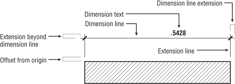
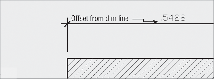
Another component of a dimension line is the dimension line extension. This is the part of the dimension line that extends beyond the extension line. Dimension line extensions are usually used only on architectural dimensions. The extension lines typically extend beyond the dimension lines in all types of dimensions. The extension line offset from origin is the distance from the beginning of the extension line to the object being dimensioned. The extensionbeyond dimension line is the distance the dimension line extends past the extension line.
You can control each of these components by creating or editing dimension styles. Dimension styles are the settings that determine the look of your dimensions. You can store multiple styles in a single drawing. The first exercise in this chapter will show you how to create a dimension style.
- For mechanical drafting in the United States, check the American Society of Mechanical Engineers (ASME) website: www.asme.org.
- For European standards, see the International Organization for Standardization (ISO) website: www.iso.org.
- For architectural standards in the United States, see the American Institute of Architects (AIA) website: www.aia.org.
Creating a Dimension Style
Dimension styles are similar to text styles. They determine the look of your dimensions as well as the size of dimensioning features, such as the dimension text and arrows. You can set up a dimension style to have special types of arrows, for instance, or to position the dimension text above or in line with the dimension line. Dimension styles also make your work easier by enabling you to store and duplicate your most common dimension settings.
AutoCAD gives you one of two default dimension styles, ISO-25 or Standard, depending on whether you use the metric or Imperial (also called English) measurement system. You’ll probably add many other styles to suit the types of drawings you’re creating. You can also create variations of a general style for those situations that call for only minor changes in the dimension’s appearance.
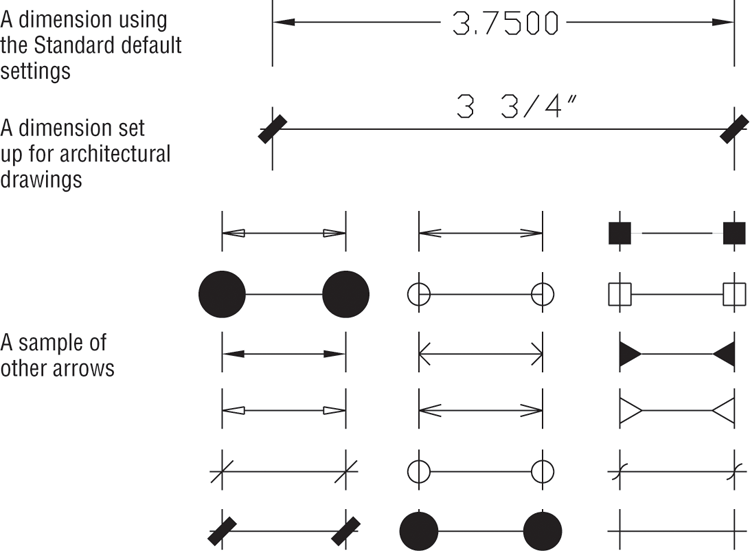
In this section, you’ll learn how to set up your own dimension style based on the Standard dimension style (see Figure 12-2). For metric users, the settings are different, but the overall methods are the same.
Figure 12-2 The AutoCAD Standard dimension style compared with an architectural-style dimension
Follow these steps to create a dimension style:
Figure 12-3 The Dimension Style Manager
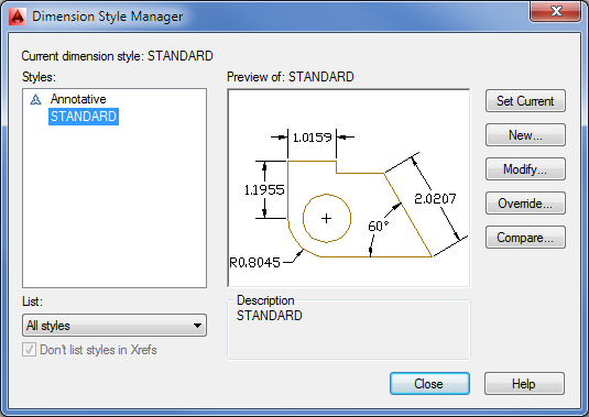
Figure 12-4 The Create New Dimension Style dialog box
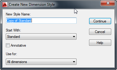
You’ve just created a dimension style called My Architectural, but at this point it’s identical to the Standard style on which it’s based. Nothing has happened to the Standard style; it’s still available if you need to use it.
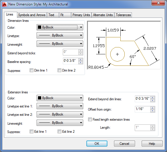
Figure 12-5 The New Dimension Style dialog box
Setting Up the Primary Unit Style
Now you need to set up your new dimension style so that it conforms to the US architectural style of dimensioning. Let’s start by changing the unit style for the dimension text. Just as you changed the overall unit style of AutoCAD to a feet-and-inches style for your bath drawing in Chapter 3, “Setting Up and Using the Drafting Tools,” you must change your dimension styles. Setting the overall unit style doesn’t automatically set the dimension unit style. Follow these steps:
Figure 12-6 The Primary Units options
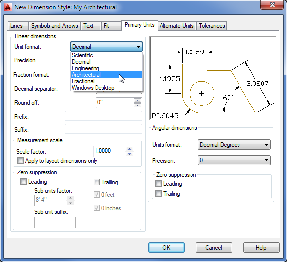
If you use the Imperial measurement system, you’ve set up My Architectural’s dimension unit style to show dimensions in feet and inches, the standard method for US construction documents. Metric users have changed the Precision value and have kept the Decimal unit system.
Setting the Height for Dimension Text
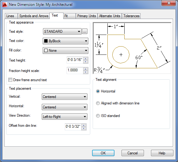
Along with the unit style, you should adjust the size of the dimension text. The Text tab of the New Dimension Style dialog box lets you set a variety of text options, including text location relative to the dimension line, style, and height.
Follow these steps to set the height of your dimension text:
Figure 12-7 The Text options
Unlike with the text you created in Chapter 10, “Adding Text to Drawings,” you specify dimension text height by its final plot size. You then specify an overall dimension scale factor that affects the sizing of all dimensioning settings, such as text and arrows.
If you want to use a specific text style for your dimensions, select a text style in the Text Style drop-down list in the Text tab. If the style you select happens to have a height specification greater than 0, that height will override any text height settings you enter in the Text tab.
Setting the Location and Orientation of Dimension Text
The default AutoCAD setting for the placement of dimension text puts the text in line with the dimension line, as shown in the example at the top of Figure 12-2 earlier in this chapter. Suppose you want the new My Architectural style to put the text above the dimension line instead, as shown in the second example in Figure 12-2. To do that, you’ll use the Text Placement and Text Alignment group options in the Text tab of the New Dimension Style dialog box:
Each time you change a setting, the graphic gives you immediate feedback about how your changes will affect your dimension style.
Choosing an Arrow Style and Setting the Dimension Scale
Next you’ll specify a different type of arrow for your new dimension style. For linear dimensions in architectural drawings, a diagonal line, or tick mark, is typically used instead of an arrow.
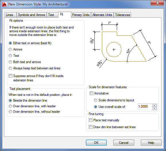
In addition, you want to set the scale for the graphical components of the dimension, such as the arrows and text. Recall from Chapter 10 that text must be scaled up in order to appear at the proper size in the final output of the drawing. Dimensions too must be scaled so that they look correct when the drawing is plotted. The arrows are controlled by settings in the Symbols And Arrows tab, and the overall scale of the dimension style is set in the Fit tab.
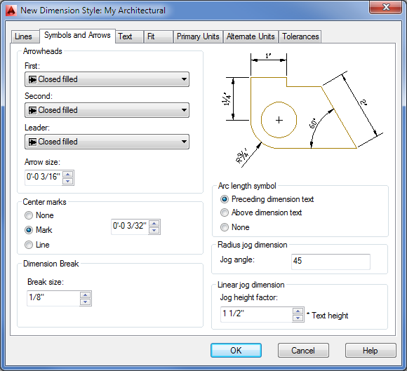
Here are the steps for specifying the arrow type and scale:
Figure 12-8 The Symbols And Arrows options
Next you need to set the behavior of the dimension line and extension lines:
Figure 12-9 The options for controlling the dimension and extension lines
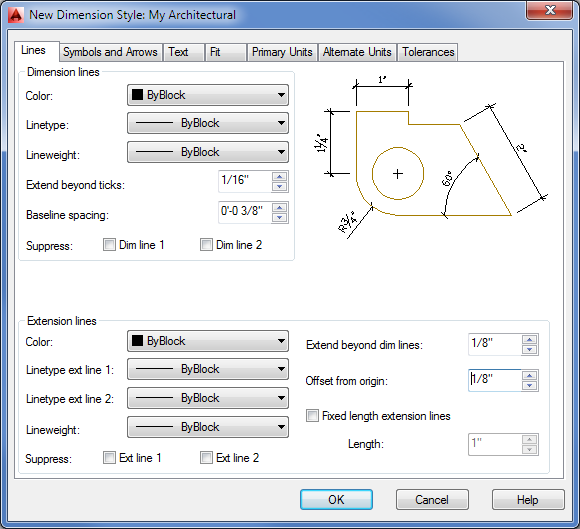
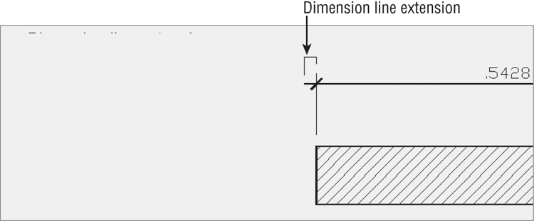

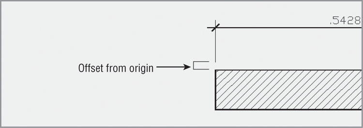
Figure 12-10 The Fit options
Setting Up Alternate Units
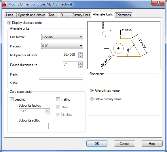
You can use the Alternate Units tab of the New Dimension Style dialog box to set up AutoCAD to display a second dimension in centimeters or millimeters. Likewise, if you’re a metric user, you can set up a second dimension to display feet and inches. The following exercise shows you how to set up alternate dimensions. You don’t have to do this exercise now; it’s here for your information. If you like, come back later and try it to see how it affects your dimensions. You can pick up the tutorial in the next section, “Setting the Current Dimension Style.”
If you decide later that you don’t want the alternate units to be displayed, you can turn them off by returning to the Modify Dimension Style dialog box and removing the check mark from the Display Alternate Units check box.
Here are the steps for setting up alternate dimensions:
Figure 12-11 The Alternate Units options
Setting the Current Dimension Style
Before you can begin to use your new dimension style, you must make it the current default:
You can also select a dimension style from the drop-down list in the Annotate tab’s Dimensions panel or the Home tab’s expanded Annotation panel. You’re now ready to use your new dimension style.
In the next set of exercises, you’ll use the My Architectural style you just created. To switch to another style, open the Dimension Style Manager again, select the style you want from the Styles list, and click Set Current, as you did in the previous exercise.
Modifying a Dimension Style
To modify an existing dimension style, open the Dimension Style Manager dialog box, highlight the style you want to edit, and then click Modify to open the Modify Dimension Style dialog box. You can then make changes to the different components of the selected dimension style. When you’ve finished making changes and closed both dialog boxes, all the dimensions associated with the edited style update automatically in your drawing. For example, if you’re not using the Annotative Scale feature and you decide you need to change the dimension scale of a style, you can open the Modify Dimension Style dialog box and change the Use Overall Scale Of value in the Scale For Dimension Features group of the Fit tab.
So far, you’ve been introduced to the various settings that let you determine the appearance of a dimension style. We haven’t discussed every option; to learn more about the other dimension style options, consult Bonus Chapter 4. There you’ll find descriptions of all the items in the New Dimension Style and Modify Dimension Style dialog boxes, plus reference material covering the system variables associated with each option.
If your application is strictly architectural, you may want to make these same dimension-style changes to the acad.dwt template file or create a set of template files specifically for architectural drawings of different scales.
Drawing Linear Dimensions
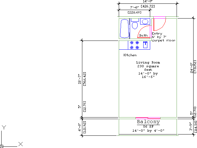
The most common type of dimension you’ll be using is the linear dimension. The linear dimension is an orthogonal dimension measuring the width and length of an object. AutoCAD provides three dimensioning tools for this purpose: Linear (Dimlinear), Continue (Dimcont), and Baseline (Dimbase). These options are readily accessible from the Annotate tab’s Dimensions panel.
In the following set of exercises, you’ll see figures displaying dimensions in both Imperial and metric units. We’ve included both measurements so that both Imperial and metric users can more easily follow the tutorial. But in your own drawing, you’ll see only one dimension value displayed above the dimension line.
Understanding the Dimensions Panel
Before you apply any dimension, you should study the Annotate tab’s Dimensions panel (see Figure 12-12). This panel contains nearly all the tools necessary to draw and edit your dimensions.
Figure 12-12 The Annotate tab’s Dimensions panel
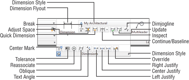
Many of the dimensioning tools discussed in this chapter can be found in the Home tab’s Annotation panel. However, since the focus of this chapter is on dimensioning, unless otherwise noted, use the panels on the Annotate tab.
Placing Horizontal and Vertical Dimensions
Let’s start by looking at the basic dimensioning tool, Linear. The Linear button (the Dimlinear command) on the Annotate tab’s Dimensions panel accommodates both the horizontal and vertical dimensions.
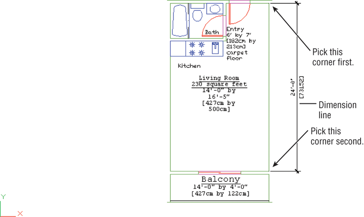
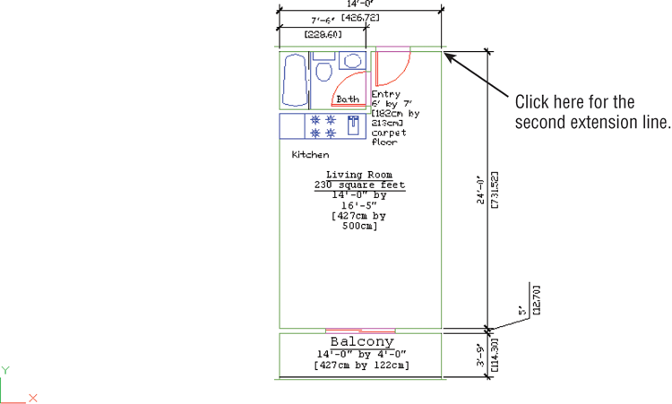
In this exercise, you’ll add a vertical dimension to the right side of the Unit plan:
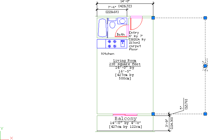
Figure 12-13 The dimension line added to the Unit drawing
Continuing a Dimension
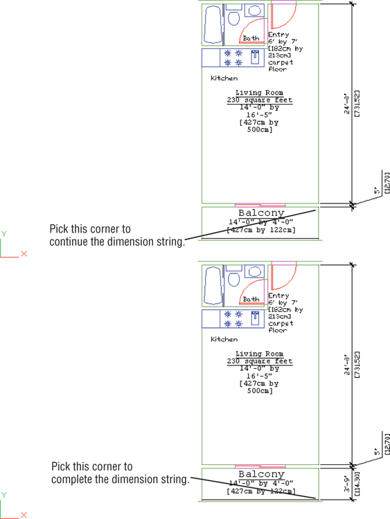
You’ll often want to enter a group of dimensions strung together in a line. For example, you may want to continue dimensioning the balcony and align the continued dimension with the dimension you just entered.
To do this, use the Continue option found in the Dimensions panel’s Continue/Baseline flyout:
If you select the wrong location for a continued dimension, you can click the Undo tool or press U↵ to undo the last dimension.
The Continue option adds a dimension from where you left off. The last-drawn extension line is used as the first extension line for the continued dimension. AutoCAD keeps adding dimensions as you continue to pick points, until you press ↵.
You probably noticed that the 5″ dimension is placed away from the dimension line with a leader line pointing to it. This is the result of the 5″ dimension’s text not having enough space to fit between the dimension extension lines. You’ll learn about dimension style settings that can remedy this problem. For now, let’s continue adding dimensions to the plan.
Figure 12-14 The dimension string, continued and completed
Continuing a Dimension from a Previous Dimension
If you need to continue a string of dimensions from an older linear dimension instead of the most recently added one, press ↵ at the Specify a second extension line origin or [Undo/Select] <Select>: prompt you saw in step 2 of the previous exercise. Then, at the Select continued dimension: prompt, click the extension line from which you want to continue.
Drawing Dimensions from a Common Base Extension Line
Another way to dimension objects is to have several dimensions originate from the same extension line. To accommodate this, AutoCAD provides the Baseline option on the Dimensions control panel and the Dimension drop-down menu.
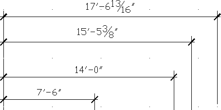
To see how this works, you’ll start another dimension—this time a horizontal one—across the top of the plan:

Figure 12-15 The bathroom with horizontal dimensions
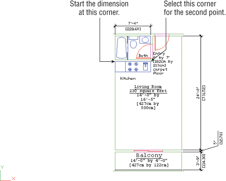
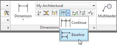
Figure 12-16 The overall width dimension
In this example, you see that the Baseline option is similar to the Continue option except that the Baseline option enables you to use the first extension line of the previous dimension as the base for a second dimension. The distance between the two horizontal dimension lines is controlled by the Baseline Spacing setting in the Lines tab of the New Dimension Style and Modify Dimension Style dialog boxes.
Continuing from an Older Dimension
You may have noticed in step 7 that you had to press ↵ twice to exit the command. As with Continue, you can draw the baseline dimension from an older dimension by pressing ↵ at the Specify a second extension line origin [Undo/Select] <Select>: prompt. You then get the Select base dimension: prompt, at which you can either select another dimension or press ↵ again to exit the command.
Adjusting the Distance Between Dimensions
As you work toward a deadline, you may find that you cut a few corners, or someone else does, when adding dimensions, and a set of parallel dimension lines isn’t accurately placed.
You can quickly adjust the spacing between dimension lines using the Adjust Space tool in the Dimensions panel:
Select dimensions to space:
Enter value or [Auto] <Auto>:Editing Dimensions
As you add more dimensions to your drawings, you’ll find that AutoCAD occasionally places the dimension text or line in an inappropriate location or that you may need to modify the dimension text. In the following sections, you’ll take an in-depth look at how you can modify dimensions to suit those special circumstances that always crop up.
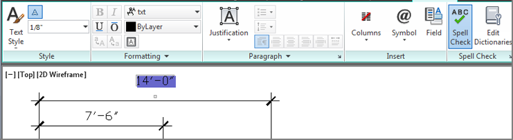
Appending Data to Dimension Text
So far in this chapter, you’ve been accepting the default dimension text. You can append information to the default dimension value or change it entirely if you need to. At the point when you see the temporary dimension dragging with your cursor, enter T↵. Then, using the less-than and greater-than (< and >) symbols, you can add text either before or after the default dimension or replace the symbols entirely to replace the default text. The Properties palette lets you modify the existing dimension text in a similar way (see Chapter 2, “Creating Your First Drawing,” for more on the Properties palette). You can open the Properties palette for a dimension by selecting the dimension and then right-clicking to open the context menu. Select Properties from there.
Let’s see how this works by changing an existing dimension’s text in your drawing:
Figure 12-17 The Text Editor tab
If you need to restore the original dimension text for a dimension whose value has been completely replaced, you can use the steps shown in the previous exercise. However, in step 3, replace the text with the <> bracket symbols.
You can also have AutoCAD automatically add a dimension suffix or prefix to all dimensions instead of just a chosen few by using the Suffix or Prefix option in the Primary Units tab of the New Dimension Style or Modify Dimension Style dialog box. See Bonus Chapter 4, “System Variables and Dimension Styles,” for more on this feature.
AutoCAD provides the associative dimensioning capability to update dimension text automatically when a drawing is edited. Objects called definition points determine how edited dimensions are updated.
The definition points are located at the same points you pick when you determine the dimension location. For example, the definition points for linear dimensions are the extension line origins. The definition points for a circle diameter are the points used to pick the circle and the opposite side of the circle. The definition points for a radius are the points used to pick the circle plus the center of the circle.
Definition points are point objects. They’re difficult to see because they’re usually covered by the feature they define. You can, however, see them indirectly by using grips. The definition points of a dimension are the same as the dimension’s grip points. You can see them by clicking a dimension. Try the following:
Figure 12-18 The grip points are the same as the definition points on a dimension.
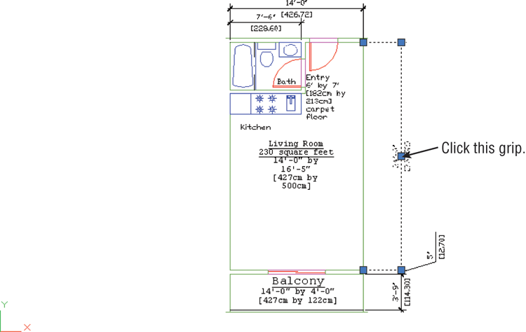
Using Grips to Make Minor Adjustments to Dimensions
The definition points, whose location you can see through their grips, are located on their own unique layer called defpoints. Definition points are displayed regardless of whether the Defpoints layer is on or off.
To give you an idea of how these definition points work, the following exercises show you how to manipulate the definition points directly.
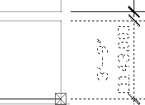
In this exercise, you’ll use coordinates to move a dimension line:
Figure 12-19 Moving the dimension line by using its grip
Enter type of dimension editing [Home/New/Rotate/Oblique]<Home>:In step 3 of the previous exercise, you saw that you could specify an exact distance for the dimension line’s new location by entering a relative polar coordinate. Cartesian coordinates work just as well. You can even use object snaps to relocate dimension lines.
Next, try moving the dimension line back by using the Perpendicular osnap:
The selected dimension line moves to align with the other vertical dimension, back to its original location.
Changing Style Settings of Individual Dimensions
In some cases, you have to change an individual dimension’s style settings in order to edit it. For example, if you try to move the text of a typical linear dimension, you may find that the text and dimension lines are inseparable. You need to make a change to the dimension style setting that controls how AutoCAD locates dimension text in relation to the dimension line. The following section describes how you can change the style settings of individual dimensions to facilitate changes in the dimension.
Moving Fixed Dimension Text
You’ve seen how dimension text is attached to the dimension line so that when the text is moved, the dimension line follows. You may encounter situations in which you want to move the text independently of the dimension line. The following steps show how you can separate dimension text from its dimension line. These steps also show how you can change a single dimension’s style settings:
Figure 12-20 The multifunction grip menu for a dimension text
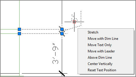
As you saw in Figure 12-20, you have a number of options for moving dimension text. The multifunction grip options are self-explanatory, but you might want to experiment with them to see how each one behaves.
When you use some of the dimension text multifunction grip options, you are changing the property of that dimension. In fact, the old way of moving dimension text involved changing a setting in the Properties palette for a selected dimension. The Move Text, Add Leader option in the Text Movement listing of the Fit category of the Properties palette lets you move the dimension text independently of the dimension line. This option is similar to the Move With Leader option in the multifunction grip menu. It also draws a leader from the dimension line to the text. Another option—Move Text, No Leader—does the same thing but doesn’t include a leader. This option has the same effect as the Move Text Only option in the multifunction grip menu. You can also set these options for a dimension style by using the Text Placement options in the Fit tab of the New Dimension Style or Modify Dimension Style dialog box.
The Properties palette gives you access to many of the settings you saw for setting up dimension styles. The main difference here is that the Properties palette affects only the dimensions you’ve selected.
In a previous exercise, you changed the format setting of a single dimension after it was placed. These settings can be made a standard part of your Architectural dimension style by using the Modify button in the Dimension Style Manager.
If you have multiple dimension styles and you want to change an existing dimension to the current dimension style, use the Update tool. Choose Update on the Dimensions panel or type Dimstyle↵A↵. Then select the dimensions you want to change and press ↵. The selected dimensions will be converted to the current style.
Editing Dimensions and Other Objects Together
It’s helpful to be able to edit a dimension directly by using its grips. But the key feature of dimensions in AutoCAD is their ability to adjust themselves automatically to changes in the drawing.
To see how this works, try moving the living room closer to the bathroom wall. You can move a group of lines and vertices by using the Stretch command and the Crossing option:
At the Select objects to stretch
by crossing-window or crossing-polygon...
Select objects: C
Specify first corner:Figure 12-21 The Stretch crossing window
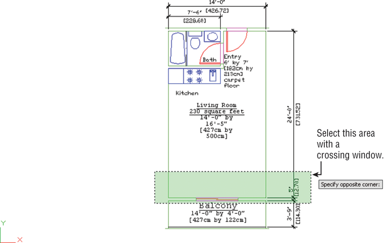
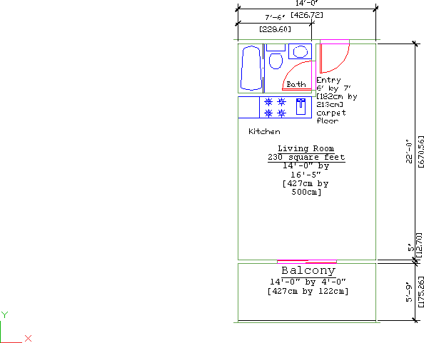
Figure 12-22 The moved wall, with the updated dimensions
You can also use the Mirror, Rotate, and Stretch commands with dimensions. The polar arrays also work, and you can use Extend and Trim with linear dimensions.
When you’re editing dimensioned objects, be sure to select the dimension associated with the object being edited. As you select objects, using the crossing window (C) or crossing polygon (CP) selection option helps you include the dimensions. For more on these selection options, see Chapter 2.
Enter dimension variable name to override or [Clear overrides]:Associating Dimensions with Objects
You’ve seen how dimensions and the objects with which they’re associated can move together so that the dimension remains connected to the object. When you’re in the process of editing a drawing, dimensions may lose their association with objects, so you may need to re-create an association between a dimension and an object. The following steps show you how this is done:
Select dimensions to reassociate
Select Objects or [Disassociated]: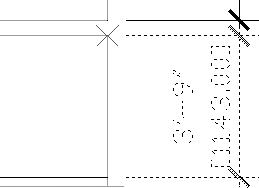
In step 3, you see an X at the location of a dimension definition point. If the definition point is already associated with an object, the X appears with a box around it. The box is a reminder that the definition point is already associated with an object and that you’ll be changing its association. In this situation, you can press ↵ to switch to the dimension’s other definition point.
Also in step 3, you have the option to select an object. This option enables you to associate the dimension with an entire object instead of with just one endpoint. If you type S↵ at that prompt in step 3, you can then select the object you want to associate with the dimension. The dimension changes so that its definition points coincide with the endpoints of the object. The dimension remains in its original orientation. For example, a vertical dimension remains vertical even if you associate the dimension with a horizontal line. In this situation, the dimension dutifully dimensions the endpoints of the line but shows a distance of 0.
Adding a String of Dimensions with a Single Operation
AutoCAD provides a method for creating a string of dimensions by using a single operation. The Qdim command lets you select a set of objects instead of having to select points. The following exercise demonstrates how the Qdim command works:
Specify dimension line position, or
[Continuous/Staggered/Baseline/Ordinate/Radius/Diameter/
datumPoint/Edit/seTtings] <Continuous>:The prompt in step 4 indicates several types of dimensions from which you can choose. For example, if you want the dimensions to originate from a single baseline, you can enter B↵ in step 4 to select the Baseline option.
The Qdim command can be a time-saver when you want to dimension a wall quickly. It may not work in all situations, but if the object you’re dimensioning is fairly simple, it can be all you need.
In this exercise, you used a simple window to select the wall. For more complex shapes, try using a crossing polygon selection window. See Chapter 2 for more on crossing polygons.
Figure 12-23 The dimensions for the wall
Adding or Removing the Alternate Dimensions
You may eventually encounter a drawing that contains alternate dimensions, as shown in some of the figures earlier in this chapter. You can remove those alternate dimensions by turning off the alternate dimension features. Here’s how it’s done:
The dimensions that use the style you just edited change to remove the alternate dimensions. You can also perform the reverse operation and add alternate dimensions to an existing set of dimensions. Follow the steps shown here, but instead of removing the check mark in step 4, add the check mark and make the appropriate setting changes to the rest of the Alternate Units tab.
Dimensioning Nonorthogonal Objects
So far, you’ve been reading about how to work with linear dimensions. You can also dimension nonorthogonal objects, such as circles, arcs, triangles, and trapezoids. In the following sections, you’ll practice dimensioning a nonorthogonal object.
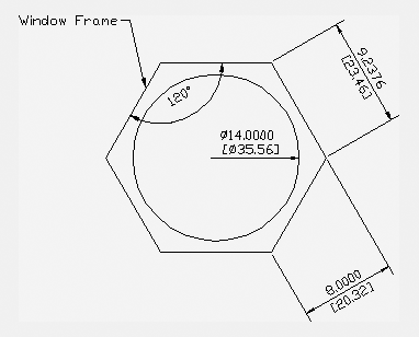
For the following exercises, you’ll use a drawing of a hexagonal-shaped window. Open the 12a-wind.dwg file from the sample files; metric users should open the 12a-wind-metric.dwg file. You can use this file to follow along.
Dimensioning Nonorthogonal Linear Distances
Now you’ll dimension the window. The unusual shape of the window prevents you from using the horizontal or vertical dimensions you’ve used already. However, choosing Aligned from the Dimension flyout in the Dimensions panel enables you to dimension at an angle:
Figure 12-24 The aligned dimension of a nonorthogonal line
Just as with linear dimensions, you can enter T↵ in step 4 to enter alternate text for the dimension.
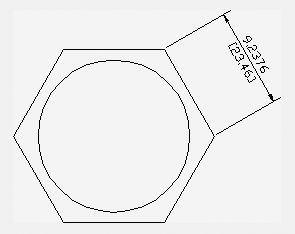
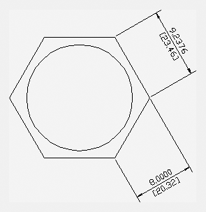
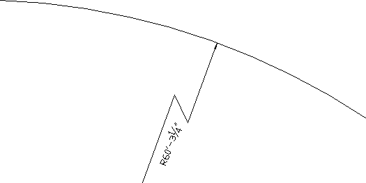
Next, you’ll dimension a face of the hexagon. Instead of its actual length, however, you’ll dimension a distance at a specified angle—the distance from the center of the face:
Figure 12-25 A linear dimension using the Rotated option
The Dimrotate command accomplishes the same thing with a slight change in the sequence of steps.
Dimensioning Radii, Diameters, and Arcs
To dimension circular objects, you use another set of options from the Dimension menu:
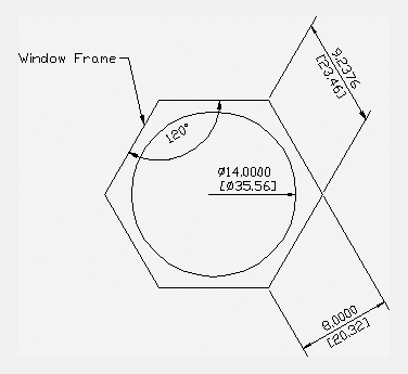
Figure 12-26 The angular dimension added to the window frame
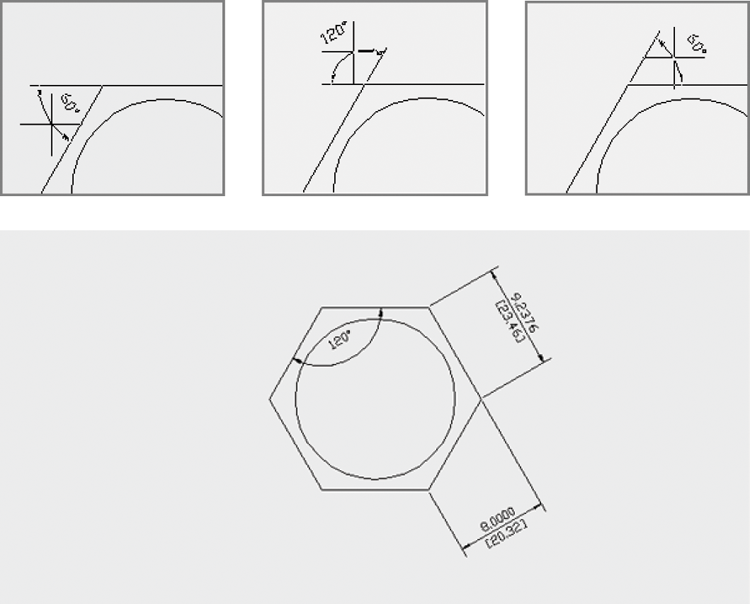
If you need to make subtle adjustments to the dimension line or text location, you can do so using grips after you place the angular dimension.
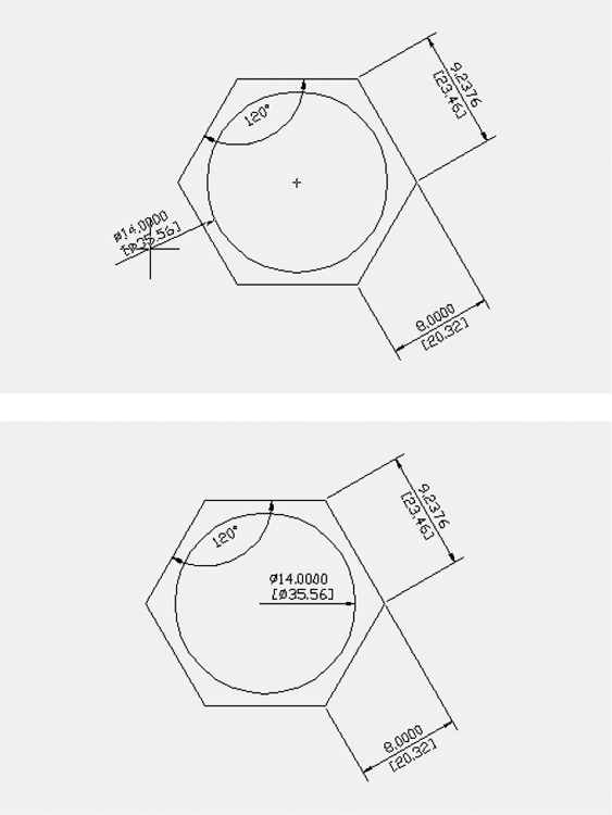
Now try the Diameter option, which shows the diameter of a circle:
Figure 12-27 Dimension showing the diameter of a circle
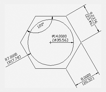
The Radius tool in the Dimension flyout on the Dimensions panel gives you a radius dimension, just as the Diameter tool provides a circle’s diameter. Figure 12-28 shows a radius dimension on the outside of the circle, but you can place it inside in a manner similar to how you place the diameter dimension. The Center Mark tool on the expanded Dimensions panel places a cross mark in the center of the selected arc or circle.
Figure 12-28 A radius dimension shown on the outside of the circle
If you need to dimension an arc or a circle whose center isn’t in the drawing area, you can use the jogged dimension. Here are the steps:
Figure 12-29 The jogged dimension in the drawing
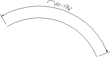
Arc lengths can also be given a dimension using the Arc Length tool. Choose the Arc Length tool from the Dimension flyout on the Dimensions panel, or enter DAR↵ at the Command prompt. At the Select Arc or polyline arc segment: prompt, select the arc you want to dimension. It can be either a plain arc or a polyline arc. Once you’ve selected the arc, the arc dimension appears and moves with the cursor. You can then select the location for the dimension.
Skewing Dimension Lines
At times, you may need to force the extension lines to take on an angle other than 90° to the dimension line. This is a common requirement of isometric drawings, in which most lines are at 30° or 60° angles instead of 90°. To facilitate nonorthogonal dimensions like these, AutoCAD offers the Oblique option:
Figure 12-30 The extension lines at 60°
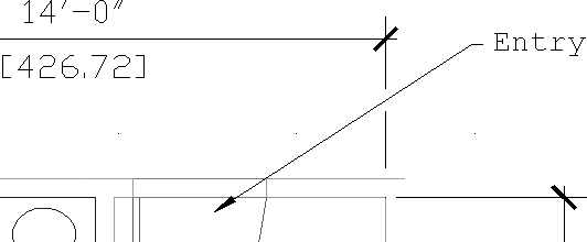
Adding a Note with a Leader Arrow
One type of dimension is something like a text-dimension hybrid. The AutoCAD Multileader tool lets you add a text note combined with an arrow that points to an object in your drawing. Multileaders are easy to use and offer the same text-formatting tools as the Mtext tool. Try the following exercise to get familiar with multileaders:

Figure 12-31 The Leaders panel
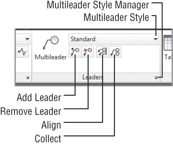
Figure 12-32 The leader with a note added
The text in the note is in the current text style unless you specify another style in the Text tab of the New Dimension Style or Modify Dimension Style dialog box. (See the section “The Text Tab” in Bonus Chapter 4 for more information.)
The Multileader tool offers a lot of options that aren’t obvious when you’re using it. In step 1 of the previous example, after choosing Multileader, you can press ↵ to modify the behavior of the Multileader tool. You’ll see the following prompt:
Enter an option [Leader type/leader lAnding/Content
 type/Maxpoints/First angle/Second angle/eXit options]
 <eXit options>:
Table 12-1 gives you a rundown of these options and their functions.
Table 12-1: The Multileader options
| Option | Function |
| Leader type | Allows you to choose between straight-line leaders, curved leaders, or no leaders. |
| leader lAnding | Determines whether a leader landing is used. The leader landing is the short line that connects the arrow to the note. Also lets you set landing distance. |
| Content type | Lets you select between Mtext or a block for the leader note. You also have the option to choose None. |
| Maxpoints | Lets you set the number of points you select for the leader. The default is 2. |
| First angle | Lets you constrain the angle of the leader line to a fixed value. |
| Second angle | Lets you constrain the angle of the arrow’s second line segment if you’re using more than two points for the Maxpoints option. |
| eXit options | Lets you return to the main part of the Multileader command to draw the leader. |
Creating Multileader Styles
Besides using the options shown in Table 12-1, you can create multileader styles to control the appearance of multileaders. Multileader styles are similar in concept to text and dimension styles. They allow you to set up the appearance of the leader under a name that you can call up anytime. For example, you may want to have one type of leader that uses a block instead of text for the note and another leader that uses a dot in place of an arrow. Alternatively, you may want to set up a style that uses curved lines instead of straight ones for the leader line. You can create a multileader style for each of these types of leader features and then switch between the leader styles, depending on the requirements of your leader note.
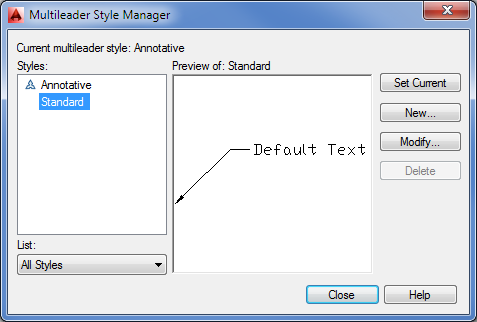
To set up or modify a multileader style, click the Multileader Style Manager tool in the Annotate tab’s Leaders panel title bar. You can also enter MLS↵ at the Command prompt. Doing so opens the Multileader Style Manager, shown in Figure 12-33. From here, you can select an existing style from the list on the left and click Modify to edit it, or you can click New to create a new one. If you click New, you’re asked to select an existing style as a basis for your new style.
Figure 12-33 The Multileader Style Manager
When you click Modify or New, the Modify Multileader Style (see Figure 12-34) or New Multileader Style dialog box opens.
Figure 12-34 The Modify Multileader Style dialog box
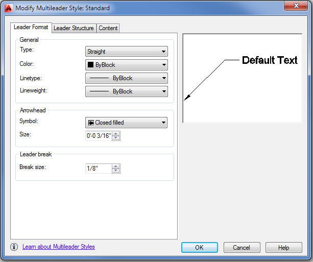
Table 12-2 describes the options in each of the tabs of the Modify Multileader Style dialog box. Some of these options are the same as those for the Multileader command.
Table 12-2: The Modify Multileader Style dialog box options
| Tab and group | Function | |
| Leader Format tab | ||
| General | Lets you set the leader line to straight or curved. You can also set the color, lineweight, and linetype for the leader line. | |
| Arrowhead | Controls the size and shape of the arrowheads. | |
| Leader Break | Controls the size of the gap in a leader line when the Leaderbreak command is applied. Leaderbreak places a break on a leader line where two leader lines cross. | |
| Leader Structure tab | ||
| Constraints | Determines the number of line segments in the leader line. You can also apply angle constraints to the leader-line segments. | |
| Landing Settings | Controls the leader-line landing segment. This is the last line segment that points to the note. | |
| Scale | Lets you control the scale of the leader components. You can either apply a fixed scale or use the Annotative option to have the drawing annotation scale apply to the leader. | |
| Content tab | ||
| Multileader Type | Lets you select the type of object that will be used for the leader note. The options are Mtext, Block, and None. | |
| Text Options | Gives you control over the way the leader note appears. You can control color, text style, size, justification, and orientation. | |
| Leader Connection | Determines the position between the leader line and the note. | |
Once you’ve set up a multileader style, you can make it the default style by selecting it from the Multileader Style drop-down list on the Annotate tab’s Leaders panel.
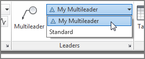
The selected style will be applied to any new multileader you add to your drawing. You can also change the style of an existing multileader. To do this, click the multileader to select it, and then select the multileader style you want from the Leaders panel drop-down list.
Editing Multileader Notes
If you need to make changes to the note portion of a multileader, you can do so by double-clicking the note. Doing so brings up the Text Editor tab in the Ribbon, allowing you to make changes as you would in a word processor.
At other times, you may want to change the leader line, arrows, or other graphic features of the multileader. For example, you may want to have all the notes aligned vertically for a neater appearance. As another option, you may want to add more leader arrows so that the note points to several objects in the drawing instead of just one.
The Leaders panel offers several tools that let you make these types of changes to your leader notes (refer back to Figure 12-31). The Add Leader and Remove Leader tools let you add or remove leaders from a multileader. Add Leader is a handy tool if you want a single note to point to several objects. The Align tool lets you align the note portion of several multileaders. Finally, the Collect tool lets you collect several multileaders that use blocks for notes into a single note.
Breaking a Dimension Line for a Leader
In a crowded drawing, your multileader arrow may have to cross over a dimension line. In many drafting conventions, when a leader line crosses over a dimension line, the dimension line must be shown with a gap.
You can apply a gap to a dimension line using the Dimbreak tool. Here’s how it works:
If you prefer to indicate a break manually, enter M↵ at the prompt in step 4. Doing so allows you to select two points on the dimension, indicating where the gap is to occur. If additional dimension or leader lines are added that cross over the dimension line, repeat your use of the Dimbreak tool. To remove an existing break, use the Remove option in step 4 by entering R↵.
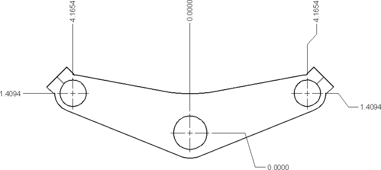
Applying Ordinate Dimensions
In mechanical drafting, ordinate dimensions are used to maintain the accuracy of machined parts by establishing an origin on the part. All major dimensions are described as x-coordinates or y-coordinates of that origin. The origin is usually an easy-to-locate feature of the part, such as a machined bore or two machined surfaces.
Figure 12-35 shows a typical application of ordinate dimensions. In the lower-right corner, note the two dimensions whose leaders are jogged. Also note the origin location in the center circle.
Figure 12-35 A drawing using ordinate dimensions
To use the Ordinate command, perform the following steps:
In steps 1 and 2, you used the UCS feature to establish a second origin in the drawing. The Ordinate Dimension tool then uses that origin to determine the ordinate dimensions. You’ll get a chance to work with the UCS feature in Chapter 22, “Using Advanced 3D Features.”
You may have noticed options in the Command window for the Ordinate Dimension tool. The Xdatum and Ydatum options force the dimension to be of the x- or y-coordinate no matter what direction the leader takes. The Mtext option opens the Text Editor tab in the Ribbon, enabling you to append or replace the ordinate dimension text. The Text option lets you enter replacement text directly through the Command window.
If you turn off Ortho mode, the dimension leader is drawn with a jog to maintain the orthogonal line segment to the dimension text (look back at Figure 12-35).
Adding Tolerance Notation
In mechanical drafting, tolerances are a key part of a drawing’s notation. They specify the allowable variation in size and shape that a mechanical part can have. To help facilitate tolerance notation, AutoCAD provides the Tolerance command, which offers common ISO tolerance symbols together with a quick way to build a standard feature-control symbol. Feature-control symbols are industry-standard symbols used to specify tolerances. If you’re a mechanical engineer or drafter, the AutoCAD tolerance notation options will be a valuable tool. However, a full discussion of tolerances requires a basic understanding of mechanical design and drafting, and it is beyond the scope of this book.
Inserting Tolerance and Datum Values
To use the Tolerance command, choose Tolerance from the expanded Dimensions panel, or type TOL↵ at the Command prompt to open the Geometric Tolerance dialog box (see Figure 12-36).
Figure 12-36 The Geometric Tolerance dialog box
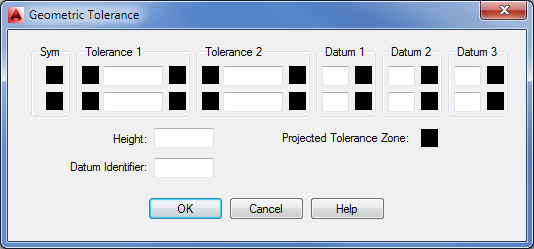
This is where you enter tolerance and datum values for the feature-control symbol. You can enter two tolerance values and three datum values. In addition, you can stack values in a two-tiered fashion.
Click a box in the Sym group to open the Symbol dialog box.
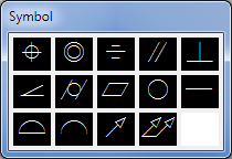
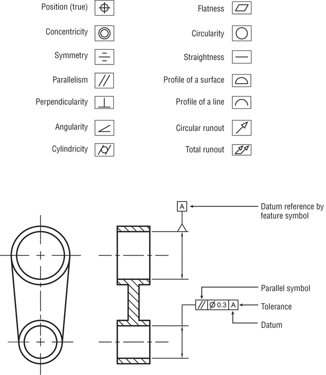
The top section of Figure 12-37 shows what each symbol in the Symbol dialog box represents. The bottom image shows a sample drawing with a feature symbol used on a cylindrical object. The symbols in the sample drawing show that the upper cylinder needs to be parallel within 0.003″ of the lower cylinder. Note that mechanical drawings often use measurements in thousandths, so 0.3 means 0.003.
Figure 12-37 The tolerance symbols
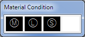
In the Geometric Tolerance dialog box, you can click a box in any of the Datum groups or a box in the right side of the Tolerance groups to open the Material Condition dialog box. This dialog box contains standard symbols relating to the maximum and minimum material conditions of a feature on the part being dimensioned.
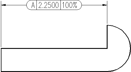
Adding Inspection Dimensions
Another type of dimension related to tolerances is the inspection dimension. This is a type of dimension notation that indicates how often the tolerances of a dimension should be checked.
To add an inspection dimension, first add a regular linear dimension as described in the early part of this chapter. Next, follow these steps:
Figure 12-38 The Inspection Dimension dialog box
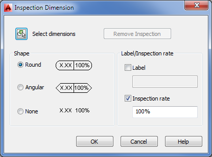
The dimension appears with the additional changes from the dialog box (see Figure 12-39).
Figure 12-39 The dimension with the additional changes