
Chapter 16
Laying Out Your Printer Output
Your set of drawings for the studio apartment building would probably include a larger-scale, more detailed drawing of the typical unit plan. You already have the beginnings of this drawing in the form of the Unit file.
As you’ve seen, the notes and dimensions you entered into the Unit file can be turned off or frozen in the Plan file so that they don’t interfere with the graphics of the drawing. The Unit file can be part of another drawing file that contains more detailed information about the typical unit plan at a larger scale. To this new drawing, you can add notes, symbols, and dimensions. Whenever the Unit file is altered, you update its occurrence in the large-scale drawing of the typical unit as well as in the Plan file. The units are thus quickly updated, and good coordination is ensured among all the drawings for your project.
Now, suppose you want to combine drawings that have different scales in the same drawing file—for example, the overall plan of one floor plus an enlarged view of one typical unit. You can do so using the layout views and a feature called Paper Space.
In this chapter, you will learn to:
- Understand Model Space and Paper Space
- Work with Paper Space viewports
- Create odd-shaped viewports
- Understand lineweights, linetypes, and dimensions in Paper Space
Understanding Model Space and Paper Space
So far, you’ve explored ways to get around in your drawing while using a single view. This single-view representation of your AutoCAD® drawing is called Model Space display mode. You can also set up multiple views of your drawing by using what are called floating viewports. You create floating viewports in layout views in what is called Paper Space mode.
To get a clear understanding of the Model Space and Paper Space modes, imagine that your drawing is actually a full-sized replica or model of the object you’re drawing. Your computer screen is your window into a “room” where this model is being constructed, and the keyboard and mouse are your means of access to this room. You can control your window’s position in relation to the object through the use of Pan, Zoom, View, and other display-related commands. You can also construct or modify the model by using drawing and editing commands. Think of this room as your Model Space.
You’ve been working on your drawings by looking through a single window into Model Space. Now, suppose you have the ability to step back and add windows with different views looking into your Model Space. The effect is as if you have several video cameras in your Model Space room, each connected to a different monitor. You can view all your windows at once on your computer screen or enlarge a single window to fill the entire screen. Further, you can control the shape of your windows and easily switch from one window to another. This is what Paper Space is like.
Paper Space lets you create and display multiple views of Model Space. Each view window, called a viewport, acts like an individual virtual screen. One viewport can have an overall view of your drawing while another can be a close-up. You can also control layer visibility individually for each viewport and display different versions of the same area of your drawing. You can move, copy, and stretch viewports and even overlap them. You can set up another type of viewport, called the tiled viewport, in Model Space. Chapter 22, “Using Advanced 3D Features,” discusses this type of viewport.
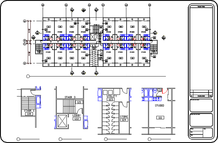
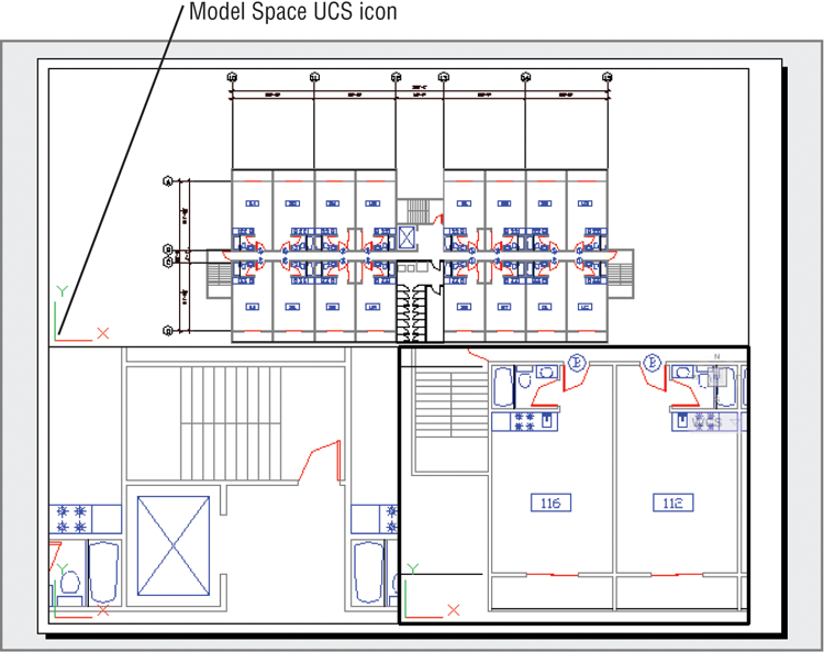
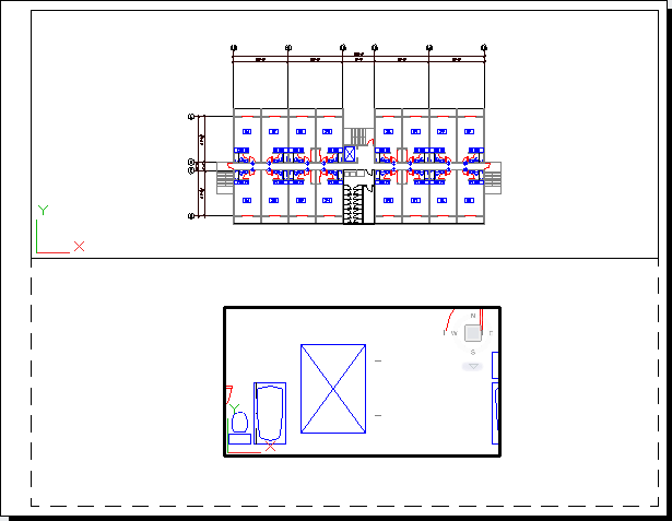
One of the more powerful features of Paper Space is the ability to plot several views of the same drawing on one sheet of paper. You can also include graphic objects such as borders and notes that appear only in Paper Space. In this function, Paper Space acts much like a page-layout program such as QuarkXPress or Adobe InDesign. You can paste up different views of your drawing and then add borders, title blocks, general notes, and other types of graphic and textual data. Figure 16-1 shows the Plan drawing set up in Paper Space mode to display several views.
Figure 16-1 Different views of the same drawing in Paper Space
Switching from Model Space to Paper Space
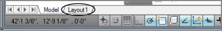
You can get to Paper Space by clicking any of the Layout tabs below the drawing area. You can also use the Quick View Layouts tool in the status bar.
If you don’t see the Model, Layout1, or Quick View Layouts tool, right-click in a blank area of the status bar and click the name of the missing tool from the context menu.
Let’s start with the basics of switching between Model and Paper Space:
Figure 16-2 Your drawing in a page preview view
This brief exercise shows you how quickly you can shift between Model Space and Paper Space by using the Model and Layout1 tabs. If you like to use the keyboard, use Ctrl+PgUp and Ctrl+PgDn to switch between tabs. The Quick View Layouts tool lets you do the same thing but offers a little more help. Try the following to see how the Quick View Layouts tool works:
Figure 16-3 The Quick View Layouts tool
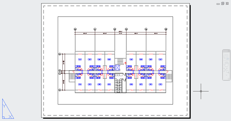
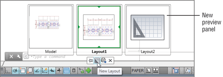
A third option is to use the preview images available from the Drawing tab at the top of the drawing area. Hover over the drawing tab and you’ll see preview images of the Model and Paper Space layouts (See Figure 16-4). The current layout is highlighted with a blue border. If you point to one of the preview images, the drawing area will temporarily display a full view of the layout. Click on the preview image to go to that layout.
Figure 16-4 The Drawing tab’s Model and Paper Space preview
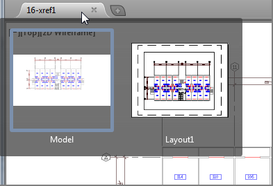
Note that when you hover over a preview image, the Plot and Publish icons appear in the top corners of the image, just as they do in the Quick View Layouts tool.
If you prefer, you can use keyboard shortcuts to switch between Model and Paper Space. Press Ctrl+PgDn to go from Model Space to Paper Space. Press Ctrl+PgUp to go from Paper Space to Model Space. If there are several Paper Space layout tabs, Ctrl+PgDn opens the next layout tab to the right and Ctrl+PgUp opens the next layout tab to the left.
Setting the Size of a Paper Space Layout
We mentioned that Paper Space is like a page-layout program, and you saw how a Paper Space layout looks like a print preview. You can set up your layout for a specific set of printer settings, including the paper size and printer.
Let’s continue with our look at Paper Space by seeing how a Paper Space layout can be set up for your printer:
Figure 16-5 The Page Setup Manager
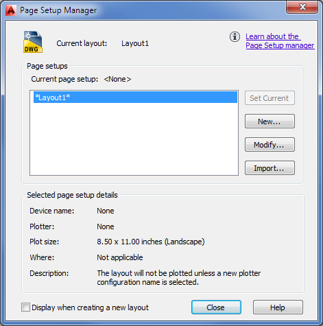
AutoCAD bases the Paper Space layout on the paper size and printer you specify in steps 4 and 5. The area shown in Paper Space reflects the area of the paper size you selected in step 4, and the paper margin shown by a dashed line is determined by the printer. If for some reason you need to change the paper size, repeat steps 2 through 5. You can also store the way you’ve set up your Paper Space layout using the Page Setup Manager you saw in step 2. See Chapter 8, “Introducing Printing, Plotting, and Layouts,” for more on this feature.
Creating New Paper Space Viewports
As you saw in Chapter 8, the different look of the layout view tells you that you’re in Paper Space. You also learned that a viewport is automatically created when you first open a layout view. The layout viewport displays an overall view of your drawing to no particular scale.
In this section, you’ll work with multiple viewports in Paper Space instead of just the default single viewport you get when you open the layout view.
This first exercise shows you how to create three new viewports at once:
Figure 16-6 The Viewports dialog box
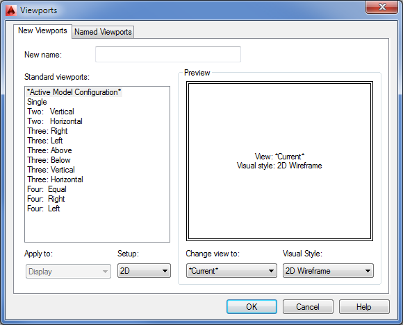
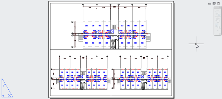
Figure 16-7 The newly created viewports
When you create new viewports, AutoCAD automatically fills them with the extents of your Model Space drawing. You can specify an exact scale for each viewport, as you’ll see later.
Notice that the dashed line representing your paper margin has disappeared. That’s because the viewports are pushed to the margin limits, thereby covering the dashed line.
You could have kept the original viewport that appeared when you first opened the Layout1 view and then added two new viewports. Completely replacing the single viewport is a bit simpler because the Viewports dialog box fits the viewports in the allowed space for you.
After you’ve set up a Paper Space layout, it remains part of the drawing. You may prefer to use Model Space for doing most of your drawing and then use Paper Space layouts for setting up views for printing. Changes that you make to your drawing in Model Space will automatically appear in your Paper Space layout viewports.
Reaching Inside Viewports
Now, suppose you need access to the objects in the viewports in order to adjust their display and edit your drawing. Try these steps:
You can move from viewport to viewport even while you’re in the middle of most commands. For example, you can issue the Line command, pick the start point in one viewport, go to a different viewport to pick the next point, and so on. To activate a different viewport, you click inside the viewport (see Figure 16-8).
You’ve seen how you can zoom into a viewport view, but what happens when you use the Zoom command while in Paper Space? Try the following exercise to find out:
This brief exercise showed that you can use the Zoom tool in Paper Space just as you would in Model Space. All the display-related commands are available, including the Pan Realtime command.
Figure 16-8 The three viewports, each with a different view of the plan
Working with Paper Space Viewports
Paper Space is intended as a page-layout or composition tool. You can manipulate viewports’ sizes, scale their views independently of one another, and even set layering and linetype scales independently.
Let’s try manipulating the shape and location of viewports by using the Home tab’s Modify panel options:
In this exercise, you clicked the viewport edge to select it for editing. If while in Paper Space you attempt to click the image in the viewport, you won’t select anything. Later, you’ll see that you can use the osnap modes to snap to parts of the drawing image in a viewport.
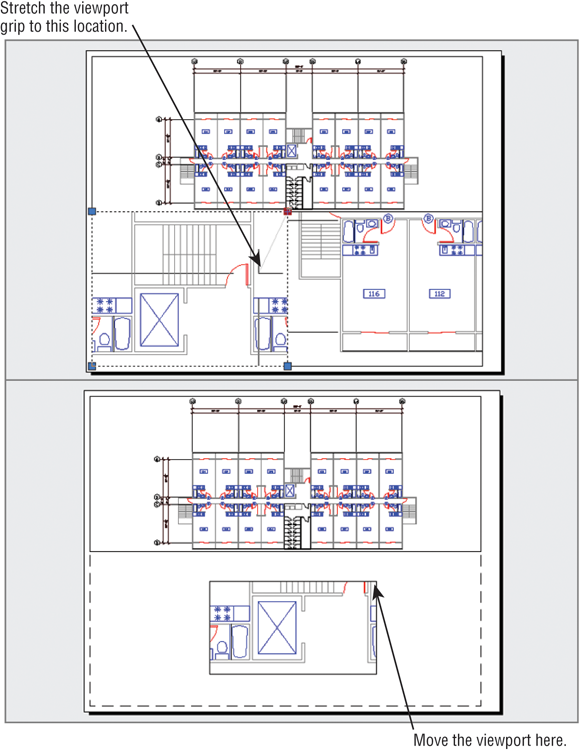
Because viewports are recognized as AutoCAD objects, you can manipulate them by using all the editing commands just as you would manipulate any other object. In the previous exercise, you moved, stretched, and erased viewports.
Figure 16-9 Stretching, erasing, and moving viewports
Next, you’ll see how layers affect viewports:
You can assign a layer, a color, a linetype, and even a lineweight to a viewport’s outline. If you put the viewport on a layer that has been turned off or frozen, that outline becomes invisible, just like any other object on such a layer. Or you can put the viewport on a nonprinting layer so that the outline will be visible while you’re editing. Making a viewport’s outlines invisible or putting them on a nonprinting layer is helpful when you want to compose a final sheet for printing. Even when turned off, the active viewport has a heavy outline around it when you switch to Floating Model Space, and all the viewports still display their views.
Scaling Views in Paper Space
Paper Space has its own unit of measure. You’ve already seen how you’re required to specify a paper size when opening a layout view to a Paper Space view. When you first enter Paper Space, regardless of the area your drawing occupies in Model Space, you’re given limits that are set by the paper size you specify in the Page Setup dialog box. If you keep in mind that Paper Space is like a paste-up area that is dependent on the printer you configured for AutoCAD, this difference of scale becomes easier to comprehend. Just as you might paste up photographs and maps representing several square miles onto an 11″ × 17″ board, so too can you use Paper Space to paste up views of scale drawings representing city blocks or houses on an 81/2 ″ × 11″ sheet of paper. But in AutoCAD, you have the freedom to change the scale and size of the objects you’re pasting up.
While in Paper Space, you can edit objects in a Model Space viewport, but to do so you must use Floating Model Space. To get to Floating Model Space, double-click inside a viewport. You can then click inside any viewport and edit in that viewport. In this mode, objects that were created in Paper Space can’t be edited. Double-click outside a viewport to go back to the Paper Space environment.
If you want to be able to print your drawing at a specific scale, you must indicate a scale for each viewport. Viewport scales are set in a way similar to the annotation scale in the Model tab. Let’s see how to put together a sheet in Paper Space and still maintain accuracy of scale:
It’s easy to adjust the width, height, and location of the viewports so that they display only the parts of the unit you want to see. While in Paper Space, use the Stretch, Move, Scale, or Rotate command to edit any viewport border, or use the viewport’s grips to edit its size and shape. The view in the viewport remains at the same scale and location while the viewport changes in size. You can move and stretch viewports with no effect on the size and location of the objects in the view. When you rotate the viewport, the view inside the viewport will also rotate.
If you need to overlay one drawing on top of another, you can overlap viewports. Use the osnap overrides to select geometry in each viewport, even while in Paper Space. This enables you to align one viewport on top of another at exact locations.
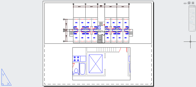
Figure 16-10 Paper Space viewport views scaled to 1⁄32″ = 1′-0″ and 3⁄16″ = 1′-0″ (1:400 and 1:100 for metric users)
You can also add a title block in Paper Space at a 1:1 scale to frame your viewports and then plot this drawing from Paper Space at a scale of 1:1. Your plot appears just as it does in Paper Space at the appropriate scale. Paper Space displays a dashed line to show you where the nonprintable areas occur near the edge of the paper.
While you’re working in Paper Space, pay close attention to whether you’re in Paper Space or Floating Model Space mode. It’s easy to pan or zoom in a Floating Model Space viewport accidentally when you intend to pan or zoom your Paper Space view. This can cause you to lose your viewport scaling or alignment with other parts of the drawing. It’s a good idea to save viewport views in case you happen to change a viewport view accidentally. You can do this by using the following procedure: Double-click inside a viewport whose view you want to save. Select View Manager from the View tab’s Views panel, and then, in the View Manager, click the New button (see “Saving Views” in Chapter 7, “Mastering Viewing Tools, Hatches, and External References,” for a description of the View Manager dialog box).
Another way to prevent your viewport view from being accidentally altered is to turn on View Lock. To do this, while in Paper Space click a viewport’s outline. Right-click to open the context menu, and then choose Display Locked ⇒ Yes. After the view is locked, you can’t pan or zoom within a viewport. This setting is also available in the viewport’s Properties palette and in the status bar to the left of the Viewport Scale tool when a viewport is selected or when you are in Floating Model Space.
Setting Layers in Individual Viewports
Another unique feature of Paper Space viewports is their ability to freeze layers independently. You can, for example, display the usual plan information in the overall view of a floor but show only the walls in the enlarged view of one unit.
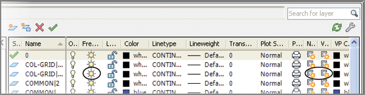
You control viewport layer visibility through the Layer Properties Manager. You may have noticed that there are three sun icons for each layer listing.
To see all of the layer options, you may need to widen the Layer Properties Manager to view all the columns. To do so, click and drag the right border of the dialog box to the right.
You’re already familiar with the sun icon farthest to the left. This is the Freeze/Thaw icon that controls the freezing and thawing of layers globally. Several columns to the right of that icon are two sun icons with transparent rectangles. These icons control the freezing and thawing of layers in individual viewports. Of this pair, the one on the left controls existing viewports and the one on the right controls settings for newly created viewports.
This exercise shows you firsthand how the sun icon for existing viewports works:
Figure 16-11 Select the VP Freeze option for the COMMON|WALL layer.
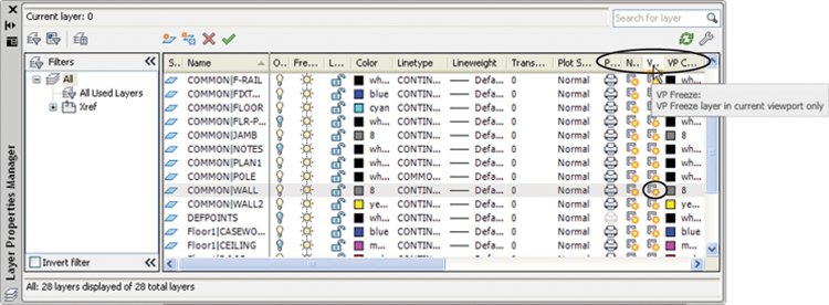
Figure 16-12 The drawing with the COMMON|WALL layer turned off in the active viewport
You may have noticed another, identical sun icon next to the one you used in the previous exercise. This icon controls layer visibility in any new viewports you create next rather than in existing viewports.
If you prefer, you can use the layer drop-down list in the Layers panel to freeze layers in individual viewports. Double-click in the viewport you want to modify, select the layer from the list, and then click the same sun icon with the small rectangle behind it.
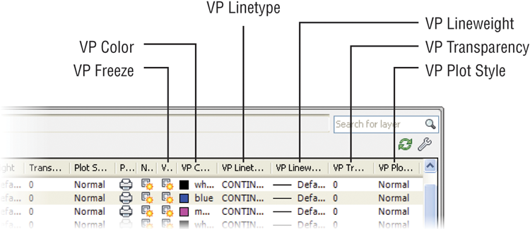
In addition to setting the visibility of layers, you can set the other layer properties—such as color, linetype, and lineweight—for each viewport. First, make sure you’re in Floating Model Space for the viewport whose layers you want to set up, and then open the Layer Properties Manager. You can set the properties for the current viewport using the VP Freeze, VP Color, VP Linetype, VP Lineweight, VP Transparency, and VP Plot Style settings for each layer (see Figure 16-13).
Figure 16-13 The VP Freeze, VP Color, VP Linetype, VP Lineweight, VP Transparency, and VP Plot Style columns in the Layer Properties Manager
This section concludes the apartment building tutorial. Although you haven’t drawn the complete building, you’ve learned all the commands and techniques you need to do so. Figure 16-14 shows you a completed plan of the first floor. To complete your floor plans and get some practice using AutoCAD, you may want to add the symbols shown in this figure to your Plan file.
Figure 16-14 A completed floor of the apartment building
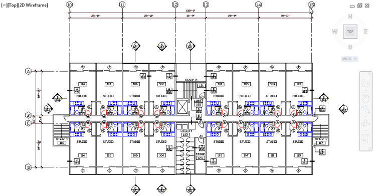
Because buildings like this one often have the same plans for several floors, the plan for the second floor can also represent the third floor. Combined with the first floor, this gives you a three-level apartment building. This project might also have a ground-level garage, which would be a separate file. You can use the Col-grid.dwg or Col-grid-metric.dwg file in the garage file as a reference for dimensions. The other symbols can be blocks stored as files that you can retrieve in other files.
Creating and Using Multiple Paper Space Layouts
You’re not limited to just one or two Paper Space layouts. You can have as many as you want, with each layout set up for a different sheet size containing different views of your drawing. You can use this feature to set up multiple drawing sheets based on a single AutoCAD drawing file. For example, suppose a client requires full sets of plans in both 1⁄8″ = 1′ scale and 1⁄16″ = 1′ scale. You can set up two Layout tabs, each with a different sheet size and viewport scale.
You can also set up different Paper Space layouts for the various types of drawings. A single drawing can contain the data for mechanical layout, equipment and furnishing, floor plans, and reflected ceiling plans. Although a project can require a file for each floor plan, a single file with multiple layout views can serve the same purpose in AutoCAD 2014.
To create new layout views, do the following:
Figure 16-15 The New Layout tool
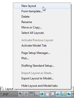
You’ve just seen how you can create a new layout using the Quick View Layouts tool. You can also right-click the Quick View Layouts tool to open a context menu that offers a New Layout option (see Figure 16-16). This option also creates a new layout, though you won’t get any feedback that a new layout has been created.
Figure 16-16 The New Layout context menu option
The Quick View Layouts context menu also includes the From Template option. The From Template option lets you create a Paper Space layout based on an AutoCAD template file. AutoCAD provides several standard layouts that include title blocks based on common sheet sizes.
The Quick View Layouts tool context menu also includes an option that enables you to move or copy tabs and to select the entire layout. Finally, if you want to delete or rename a layout, click the Quick View Layouts tool and then right-click in the preview panel for the layout you want to edit. You can then select Delete or Rename from the context menu that appears. If you select Delete, you’ll see a warning message telling you that AutoCAD will permanently delete the layout you have chosen to delete. Click OK to confirm your deletion.
Creating Odd-Shaped Viewports
In many situations, a rectangular viewport doesn’t provide a view appropriate for what you want to accomplish. For example, you might want to isolate part of a floor plan that is L shaped or circular. You can create viewports for virtually any shape you need. You can grip-edit a typical rectangular viewport to change its shape into a trapezoid or other irregular four-sided polygon. You can also use the Clip tool to create more complex viewport shapes, as the following exercise demonstrates.
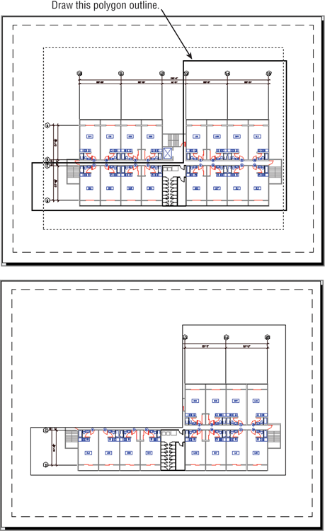
Follow these steps to set up a layout view that shows only the lower apartment units and the elevators and stairs:
The new viewport shape gives you more flexibility in isolating portions of a drawing. This can be especially useful if you have a large project that is divided into smaller sheets. You can set up several layout views, each displaying a different portion of the plan.
Figure 16-17 Drawing a polygon outline for a viewport
What if you want a viewport that isn’t rectilinear? This exercise shows you how to create a circular viewport:
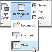
Figure 16-18 A circular viewpoint
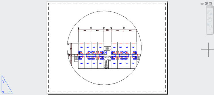
To simplify this exercise, you were asked to draw a circle as the basis for a new viewport. However, you aren’t limited to circles; you can use a closed polyline or spline of any shape. (See Chapter 19, “Drawing Curves,” for a detailed discussion of polylines and splines.) You can also use the Polygon tool on the Home tab’s Draw panel to create a shape and then turn it into a viewport.
If you look carefully at the series of prompts for the previous exercise, you’ll notice that the Layout Viewports Object tool invokes a command-line version of the Vports command (-vports), which offers some options that the standard Vports command doesn’t. The following options are available with the command-line version of Vports:
_-VPORTS
Specify corner of viewport or
[ON/OFF/Fit/Shadeplot/Lock/Object/Polygonal/Restore/LAyer/2/3/4] <Fit>:
You used two of the options—Polygonal and Object—in the two previous exercises.
Understanding Lineweights, Linetypes, and Dimensions in Paper Space
The behavior of several AutoCAD features depends on whether you’re in Paper Space or Model Space. The most visible of these features are lineweights, linetypes, and dimensions. In the following sections, you’ll take a closer look at these features and see how to use them in conjunction with Paper Space.
Controlling and Viewing Lineweights in Paper Space
Lineweights can greatly improve the readability of technical drawings. You can make important features stand out with bold lineweights while keeping the noise of smaller details from overpowering a drawing. In architectural floor plans, walls are traditionally drawn with heavier lines so that the outline of a plan can be easily read. Other features exist in a drawing for reference only, so they’re drawn in a lighter weight than normal.
In Chapter 9, “Understanding Plot Styles,” you saw how to control lineweights in AutoCAD by using plot style tables. You can apply either a named plot style table or a color plot style table to a drawing. If you already have a library of AutoCAD drawings, you may want to use color plot style tables for backward compatibility. AutoCAD also enables you to assign lineweights directly to layers or objects and to view the results of your lineweight settings in Paper Space.
Here’s an exercise that demonstrates how to set lineweights directly:
Figure 16-19 The Lineweight dialog box
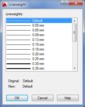
Although you set the lineweights for the layers in the drawing, you need to make a few more changes to the file settings before they’re visible in Paper Space:
Figure 16-20 The Lineweight Settings dialog box
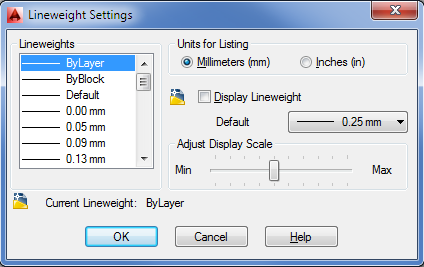
Figure 16-21 An enlarged view of the plan with lineweights displayed
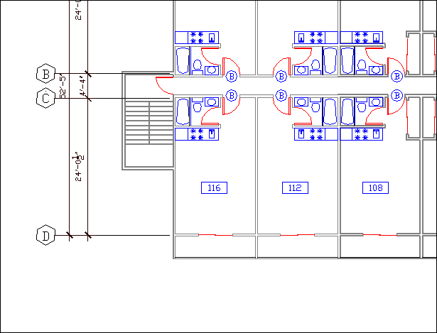
With the ability to display lineweights in Paper Space, you have better control over your output. Instead of using a trial-and-error method to print your drawing and then checking your printout to see whether the lineweights are correct, you can see the lineweights on your screen.
This exercise showed you how to set lineweights so that they appear in Paper Space as they will when you plot your drawing. If you normally plot your drawings in black, you can go one step further and set all your layer colors to black to see how your plots will look. But you’ll need to save your layer settings so you can restore the layers to their original colors. Another way to view your drawing in black and white without affecting your layer settings is to use the color plot style table described in Chapter 9.
The Lineweight Settings Dialog Box
The Lineweight Settings dialog box includes a few other settings that you didn’t use in the previous exercise. Here is a description of those settings for your reference:
Linetype Scales and Paper Space
As you’ve seen in previous exercises, you must carefully control drawing scales when creating viewports. Fortunately, this is easily done through the Properties palette. Although Paper Space offers the flexibility of combining images of different scale in one display, it also adds to the complexity of your task in controlling that display. Your drawing’s linetype scale in particular needs careful attention.
In Chapter 5, “Keeping Track of Layers and Blocks,” you saw that you had to set the linetype scale to the scale factor of the drawing in order to make the linetype visible. If you intend to plot that same drawing from Paper Space, you have to set the linetype scale back to 1 to get the linetypes to appear correctly. This is because AutoCAD faithfully scales linetypes to the current unit system. Remember that Paper Space units are different from Model Space units. When you scale a Model Space image down to fit in the smaller Paper Space area, the linetypes remain scaled to the increased linetype scale settings. In the Chapter 5 example, linetypes are scaled up by a factor of 24. This causes noncontinuous lines to appear as continuous in Paper Space because you see only a small portion of a greatly enlarged noncontinuous linetype.
The Psltscale system variable enables you to determine how linetype scales are applied to Paper Space views. You can set Psltscale so that the linetypes appear the same regardless of whether you view them directly in Model Space or through a viewport in Paper Space. By default, this system variable is set to 1. This causes AutoCAD to scale all the linetypes uniformly across all the viewports in Paper Space. You can set Psltscale to 0 to force the viewports to display linetypes exactly as they appear in Model Space. Psltscale is not a global setting. You must set Psltscale for each layout view that you create; otherwise, the default value of 1 will be used.
You can also control this setting in the Linetype Manager dialog box (type LT↵). When you click the Show Details button, you see a setting called Use Paper Space Units For Scaling in the lower-left corner. When this check box is selected, Psltscale is set to 1. When it isn’t selected, Psltscale is set to 0.
Dimensioning in Paper Space Layouts
At times, you may find it more convenient to add dimensions to your drawing in Paper Space rather than directly on your objects in Model Space. This can be useful if you have a small project with several viewports in a layout and you want to keep dimensions aligned between viewports. You have two basic options when dimensioning Model Space objects in Paper Space. The Associative Dimensioning feature can make quick work of dimensions for layout views containing drawings of differing scales. Alternatively, if you prefer not to use Associative Dimensioning, you can adjust settings for individual dimension styles.
Using Associative Dimensioning in Paper Space
Perhaps the simplest way to dimension in Paper Space is to use the Associative Dimensioning feature. With this feature turned on, you can dimension Model Space objects while in a Paper Space layout. Furthermore, Paper Space dimensions of Model Space objects are automatically updated if the Model Space object is edited.
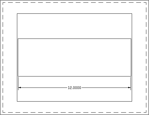
Try the following exercise to see how Associative Dimensioning works:
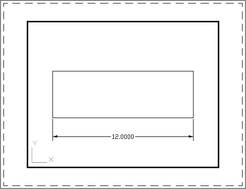
Next, you’ll use the rectangle you drew in Model Space to test the Associative Dimensioning feature in the Layout1 view:
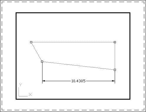
You’ve just seen how you can dimension an object in Model Space while in Paper Space. You can dimension Model Space Xrefs in Paper Space in much the same way. The only difference is that changes to the Xref file don’t automatically update dimensions made in Paper Space. You need to employ the Dimregen command to refresh Paper Space dimensions of Xref objects.
Updating Associative Dimensions
If you use a wheel mouse to pan and zoom in a Floating Model Space viewport, you may need to use the Dimregen command to refresh an associative dimension. To do so, type Dimregen↵ at the command line. You can also use Dimregen to refresh dimensions from drawings that have been edited in earlier versions of AutoCAD or, as mentioned already, to refresh dimensions of objects contained in external references.
Paper Space Dimensioning Without Associative Dimensioning
In some situations, you may not want to use Associative Dimensioning although you still want to dimension Model Space objects in Paper Space. For example, you might be in an office that has different versions of AutoCAD, or you might be sharing your drawings with other offices that aren’t using AutoCAD 2014 and the use of Associative Dimensioning creates confusion.
To dimension Model Space objects in Paper Space without Associative Dimensioning, you need to have AutoCAD adjust the dimension text to the scale of the viewport from which you’re dimensioning. You can have AutoCAD scale dimension values in Paper Space so that they correspond to a viewport zoom-scale factor. The following steps show you how this setting is made:
Remember that you can snap to objects in a floating viewport so you can add dimensions as you normally would in Model Space. If you’re dimensioning objects in viewports of different scales, you need to set up multiple dimension styles, one for each viewport scale.
Other Uses for Paper Space
The exercises in the preceding sections should give you a sense of how you work in Paper Space and layout views. We’ve given examples that reflect common uses of Paper Space. Remember that Paper Space is like a page-layout portion of AutoCAD—separate yet connected to Model Space through viewports.
You needn’t limit your applications to floor plans. You can take advantage of Paper Space with interior and exterior elevations, 3D models, and detail sheets. When used in conjunction with the raster-import capabilities in AutoCAD, Paper Space can be a powerful tool for creating large-format presentations.