
Chapter 20
Getting and Exchanging Data from Drawings
Drawings in Autodesk® AutoCAD® software contain a wealth of data—graphic information such as distances and angles between objects as well as precise areas and the properties of objects. However, as you become more experienced with AutoCAD, you’ll also need data of a different nature. For example, as you begin to work in groups, the various settings in a drawing become important. You’ll need statistics on the amount of time you spend on a drawing when you’re billing computer time. As your projects become more complex, file maintenance requires a greater degree of attention. To take full advantage of AutoCAD, you’ll want to exchange information about your drawing with other people and other programs.
In this chapter, you’ll explore the ways in which all types of data can be extracted from AutoCAD and made available to you, to your coworkers, and to other programs. First you’ll learn how to obtain specific data about your drawings. Then you’ll look at ways to exchange data with other programs—such as word processors, desktop publishing software, and even other CAD programs.
In this chapter, you will learn to:
- Find the area of closed boundaries
- Get general information
- Use the DXF file format to exchange CAD data with other programs
- Use AutoCAD drawings in page layout programs
- Use OLE to import data
Finding the Area of Closed Boundaries
One of the most frequently sought pieces of data you can extract from an AutoCAD drawing is the area of a closed boundary. In architecture, you often need to find the area of a room or the footprint of a building. In civil engineering, you may want to determine the area covered by the boundary of a property line or the area of cut for a roadway. In the following sections, you’ll learn how to use AutoCAD to obtain exact area information from your drawings.
Finding the Area of an Object
Architects, engineers, and facilities planners often need to know the square footage of a room or a section of a building. A structural engineer might want to find the cross-sectional area of a beam. In this section, you’ll practice determining the areas of regular objects.
First you’ll determine the square-footage area of the living room and entry of your studio unit plan:
Figure 20-1 Selecting the points to determine the area of the living room and entry
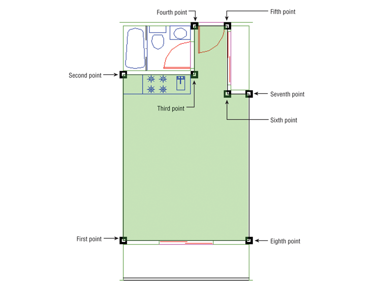
Area = 39570.00 square in. (274.7917 square ft), Perimeter = 76′-0″The number of points you can pick to define an area is limitless, which means you can obtain the areas of complex shapes.
Using Hatch Patterns to Find Areas
Hatch patterns are used primarily to add graphics to your drawing, but they can also serve as a means for finding areas. You can use any hatch pattern you want because you’re interested only in the area it reports back to you. You can also set up a special layer devoted to area calculations and then add to this layer the hatch patterns you use to find areas. That way, you can turn off the hatch patterns so that they don’t plot, or you can turn off the Plot setting for that layer to ensure that it doesn’t appear in your final output.
To practice using hatch patterns to find an area, do the following:
Figure 20-2 After you click a point on the interior of the plan to place a hatch pattern, an outline of the area is highlighted by a dotted line and the hatch appears.
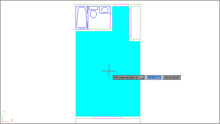
Area = 39570.00 square in. (274.7917 square ft), Perimeter = 76′-0″If you need to recall the last area calculation value you received, enter 'Setvar↵Area↵. The area is displayed in the prompt. Enter 'Perimeter↵ to get the last perimeter calculated.
The Hatch command creates a hatch pattern that conforms to the boundary of an area. This feature, combined with the ability of the Measuregeom command to find the area of a hatch pattern, makes short work of area calculations. Another advantage of using hatch patterns is that, by default, hatch patterns avoid islands within the boundary of the area you’re trying to find.
The area of a hatch pattern is also reported by the Properties palette. Select the hatch pattern whose area you want to find, and then right-click and select Properties. Scroll down to the bottom of the Geometry group and you’ll see the Area listing for the hatch pattern you selected. You can select more than one hatch pattern and find the cumulative area of the selected hatch patterns in the Properties palette.
Adding and Subtracting Areas with the Area Command
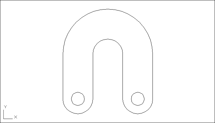
Hatch patterns work extremely well for finding areas, but if you find that you can’t use hatch patterns for some reason, you have another alternative. You can still use a command called Boundary to generate a polyline outline of an enclosed boundary and then obtain the area of the outline using the Measuregeom command (Measure on the Home tab’s Utilities panel). If islands are present within the boundary, you have to use the Subtract feature of the Measuregeom command to remove their area from the overall boundary area. In this section, you’ll use the example of the flange part, which contains two islands, in the form of the two circles, at the lower end (see Figure 20-3).
Figure 20-3 A flange to a mechanical device
By using the Add and Subtract options of the Measuregeom command, you can maintain a running total of several separate areas being calculated, a capability that gives you flexibility in finding areas of complex shapes. This section guides you through the use of these options.
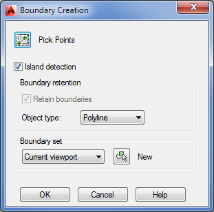
For the following exercise, you’ll use a flange shape that contains circles. This shape is composed of simple arcs, lines, and circles. Use these steps to see how you can keep a running tally of areas:
Figure 20-4 The Boundary Creation dialog box
Area = 27.7080, Perimeter = 30.8496
Total area = 27.7080Total area = 0.6070, Circumference = 2.7618
Total area = 27.1010Total area = 0.6070, Perimeter = 2.7618
Total area = 26.4940In this exercise, you first selected the main object outline and then subtracted the island objects. You don’t have to follow this order; you can start by subtracting areas to get negative area values and then add other areas to come up with a total. You can also alternate between Add and Subtract modes, in case you forget to add or subtract areas.
You may have noticed that the Measuregeom Command prompt offered Specify first corner point or [Object/Add area/Subtract area/eXit]: as the default option for both the Add Area and Subtract Area modes. Instead of using the Object option to pick the circles, you can start selecting points to indicate a rectangular area as you did in the first exercise in this chapter.
Whenever you press ↵ while selecting points for an area calculation, AutoCAD automatically connects the first and last points and returns the calculated area. If you’re in Add or Subtract mode, you can then continue to select points, but the additional areas are calculated from the next point you pick.
As you can see from these exercises, it’s simpler to outline an area first with a polyline wherever possible and then use the Object option to add and subtract area values of polylines.
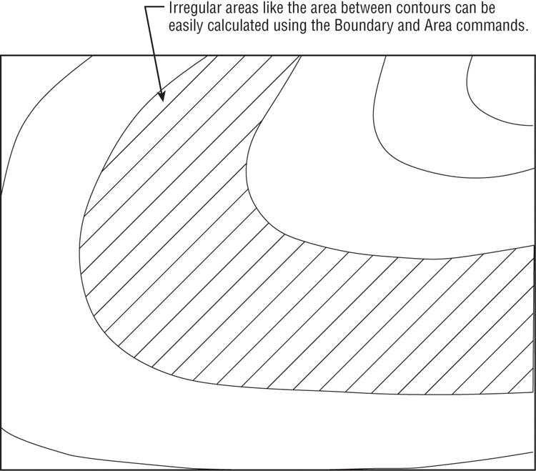
In this example, you obtained the area of a mechanical object. However, the same process works for any type of area you want to calculate. It can be the area of a piece of property on a topographical map or the area of a floor plan. For example, you can use the Object option to find an irregular shape such as the one shown in Figure 20-5, as long as it’s a closed polyline.
Figure 20-5 The site plan with an area to be calculated
When issued through the keyboard as MEA↵, the Measuregeom command offers a number of other options for measuring your drawing. The options appear in the Command window as [Distance/Radius/Angle/ARea/Volume]<Distance> or at the cursor as a Dynamic Input option. These options are automatically selected when you click the related tool from the Measure flyout on the Utilities panel. Remember that to use an option, type the capitalized letter or letters of the option shown in the list. Table 20-1 gives you descriptions of the options and how they are used.
Table 20-1: The Measuregeom command options
| Option | Use |
| Distance | Returns the distance between two points. Type D↵ and select two points. You can also measure cumulative distances by typing M↵ after selecting the first point. |
| Radius | Returns the radius of an arc or circle. Type R↵ and select an arc or circle. |
| Angle | Returns the angle of an arc or the angle between two lines. Type A↵ and select the arc or two nonparallel lines. |
| ARea | Returns the area of a set of points or boundary. Type AR↵ to use this option. See previous exercises for instruction on the use of this option. |
| Volume | Returns the 3D volume based on an area times height. |
| eXit | Exits the current option. You can also press the Esc key. |
Getting General Information
So far in this book, you’ve seen how to get data about the geometry of your drawings. AutoCAD also includes a set of tools that you can use to access the general state of your drawings. You can gather information about the status of current settings in a file or the time at which a drawing was created and last edited.
In the following sections, you’ll practice extracting this type of information from your drawing, using the tools found in the Tools tab’s Inquiry panel.
Determining the Drawing’s Status
When you work with a group of people on a large project, keeping track of a drawing’s setup becomes crucial. You can use the Status command to obtain general information about the drawing on which you’re working, such as the base point, current mode settings, and workspace or computer memory use. The Status command is especially helpful when you’re editing a drawing on which someone else has worked because you may want to identify and change settings for your own style of working. Click Drawing Utilities ⇒ Status from the Application menu to display a list like the one shown in Figure 20-6.
Figure 20-6 The Status screen of the AutoCAD command-line interface
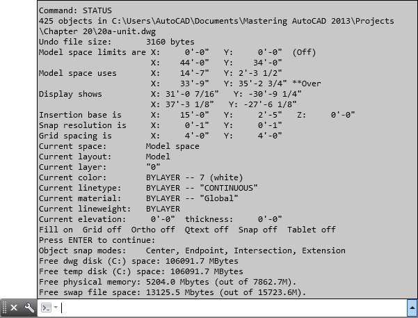
Here is a brief description of each item on the Status command’s display in the expanded command line. Note that some of the items you see on the screen will vary somewhat from what we’ve shown here, but the information applies to virtually all situations except where noted:
When you’re in Paper Space, the Status command displays information regarding the Paper Space limits. See Chapter 16, “Laying Out Your Printer Output,” for more on Model Space and Paper Space.
In addition to being useful in understanding a drawing file, the Status command is an invaluable tool for troubleshooting. Frequently, a technical support person can isolate problems by using the information provided by the Status command.
Keeping Track of Time
The Time command enables you to keep track of the time spent on a drawing for billing or analysis purposes. You can also use the Time command to check the current time and find out when the drawing was created and most recently edited. Because the AutoCAD timer uses your computer’s time, be sure the time is set correctly in Windows.
To access the Time command, enter Time↵ at the Command prompt. You get a message like the one shown in Figure 20-7.
Figure 20-7 The Time screen in the AutoCAD command-line interface
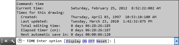
The first four lines of this message tell you the current date and time, the date and time the drawing was created, and the last time the drawing was saved.
The fifth line shows the total time spent on the drawing from the point at which the file was opened. This elapsed timer lets you time a particular activity, such as changing the width of all the walls in a floor plan or redesigning a piece of machinery. The last line tells you the timing of the next automatic save.
You can turn the elapsed timer on or off or reset it by entering ON, OFF, or Reset at the prompt shown at the bottom of the message, or you can press ↵ to exit the Time command.
Getting Information from System Variables
If you’ve been working through this book’s ongoing studio apartment building tutorial, you’ll have noticed that we’ve occasionally mentioned a system variable in conjunction with a command. You can check the status or change the setting of any system variable while you’re in the middle of another command. To do this, you type an apostrophe (') followed by the name of the system variable at the Command prompt.
For example, if you start to draw a line and suddenly decide you need to restrict your cursor movement to 45°, you can do the following:
You can also recall information such as the last area or distance calculated by AutoCAD. Type Setvar↵Area↵ to read the last area calculation. The Setvar command also lets you list all the system variables and their status as well as access each system variable individually by entering 'Setvar↵?↵. You can then indicate which variables to list using wildcard characters such as the asterisk or question mark. For example, you can enterg*↵ to list all the system variables that start with the letter G.
Many system variables give you direct access to detailed information about your drawing. They also let you fine-tune your drawing and editing activities. In Bonus Chapter 4, “System Variables and Dimension Styles,” you’ll find all the information you need to familiarize yourself with the system variables. Don’t feel that you have to memorize them all at once; just be aware that they’re available.
Keeping a Log of Your Activity
At times, you may find it helpful to keep a log of your activity in an AutoCAD session. A log is a text file containing a record of your activities. It can also contain notes to yourself or others about how a drawing is set up. Such a log can help you determine how frequently you use a particular command, or it can help you construct a macro for a commonly used sequence of commands.
The following exercise demonstrates how to save and view a detailed record of an AutoCAD session by using the Log feature:
C:Documents and SettingsUser NameLocal SettingsApplication
DataAutodeskAutoCAD 2014R19.1enuYou can quickly turn the Maintain A Log File feature on and off by typing Logfileon↵ and Logfileoff↵, respectively, at the Command prompt. As you can see in step 7, the log file is given the name of the drawing file from which the log is derived, with some additional numeric values. Because the Flange log file is a standard text file, you can easily send it to other members of your workgroup or print it for a permanent record.
Capturing and Saving Text Data from the AutoCAD Text Window
If you’re working in groups, it’s often helpful to have a record of the status, editing time, and system variables for particular files readily available to other group members. It’s also convenient to keep records of block and layer information so you can see whether a specific block is included in a drawing or what layers are normally on or off.
You can use the Windows Clipboard to capture and save such data from the AutoCAD Text Window. The following steps show you how it’s done:
If you want to copy only a portion of the command-line data to the Clipboard, perform the following steps:
You may notice other options on the context menu: Recent Commands, AutoComplete, Paste, Paste To Command Line, Transparency, and Options. Choosing Recent Commands displays a list of the most recent commands. For most activities, you’ll use a handful of commands repeatedly; the Recent Commands option can save you time by giving you a shortcut to those commands that you use the most.
The AutoComplete feature automatically completes a command name as you type it. For example, if you start to type cha for the Change command, the AutoComplete feature will display a list of commands and system variables that begin with cha in a drop-down menu. As you continue to type, the list will also change to narrow down the options based on what you type. See Chapter 26, “Customizing Toolbars, Menus, Linetypes, and Hatch Patterns,” for more on the AutoComplete options.
The Paste options paste the first line of the contents of the Clipboard into the command line or input box of a dialog box. This can be useful for entering repetitive text or for storing and retrieving a frequently used command. Choosing Options opens the Options dialog box.
Items copied to the Clipboard from the command-line interface or the AutoCAD Text Window can be pasted into dialog box input boxes. This can be a quick way to transfer layers, linetypes, or other named items into dialog boxes. You can even paste text into the drawing area.
Storing Searchable Information in AutoCAD Files
As you start to build a library of AutoCAD files, you’ll have to start thinking about how to manage them. Keeping track of AutoCAD files can be a daunting task. Most AutoCAD users start to name files by their job number to keep things organized. But even the best organization schemes don’t help if you need to find that one special file among thousands of files in your library. In this section, you’ll learn how to include information in an AutoCAD file that you can use later to locate the file with the Windows Search utility.
AutoCAD includes DesignCenter™ and the Content Explorer™, which are tools that can help you locate a file more easily based on a keyword or description. Chapter 27, “Managing and Sharing Your Drawings,” provides a complete discussion of DesignCenter and the Content Explorer.
To add general, searchable information about your drawing file, use the drawing’s Properties dialog box (see Figure 20-8). Choose Drawing Utilities ⇒ Drawing Properties from the Application menu.
Figure 20-8 A drawing’s properties
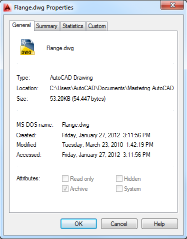
Here are descriptions of the four tabs in this dialog box:
Searching for AutoCAD Files
After you’ve included information in a file’s Properties palette, you can use the AutoCAD DesignCenter, Content Explorer, the File dialog box, or the Windows Search function to locate your file.
A Find option is also located in the Tools menu in the upper-right corner of the AutoCAD Select File dialog box. To access it, click the Open tool from the Quick Access toolbar; then, in the Select File dialog box, choose Tools ⇒ Find.
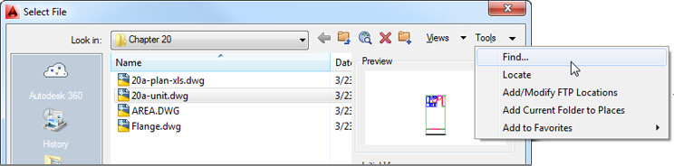
This option opens a Find dialog box that works just like the Windows Search Results window.
Recovering Corrupted Files
No system is perfect. Eventually, you’ll encounter a file that is corrupted in some way. Two AutoCAD tools can frequently salvage a corrupted file:
You can access these tools from the Drawing Utilities option on the Application menu. More often than not, these tools will do the job, although they aren’t a panacea for all file corruption problems. In the event that you can’t recover a file even with these tools, make sure your computer is running smoothly and that other systems aren’t faulty.
If for some reason your computer shuts down while you’re in the middle of editing a file, you’ll see the Drawing Recovery Manager the next time you start AutoCAD. The Drawing Recovery Manager lets you recover the file on which you were working when AutoCAD unexpectedly shut down. This feature works just like the file recovery feature in Microsoft Office: A panel appears to the left of the AutoCAD Text Window showing you a list of recoverable files. You can then select the filename from the panel to open the file. You can find the Drawing Recovery Manager in the Application menu under Drawing Utilities ⇒ Open The Drawing Recovery Manager.
Using the DXF File Format to Exchange CAD Data with Other Programs
AutoCAD offers many ways to share data with other programs. Perhaps the most common type of data exchange is to share drawing data with other CAD programs. In the following sections, you’ll see how to export and import CAD drawings using the DXF file format.
A Drawing Interchange Format (DXF) file is a plain-text file that contains all the information needed to reconstruct a drawing. It’s often used to exchange drawings created with other programs. Many CAD and technical drawing programs, including some 3D programs, can generate or read files in DXF format. You might want to use a 3D program to view your drawing in a perspective view, or you might have a consultant who uses a different CAD program that accepts DXF files.
Be aware that not all programs that read DXF files accept all the data stored therein. Many programs that claim to read DXF files throw away much of the DXF files’ information. Attributes are perhaps the most commonly ignored objects, followed by many of the 3D objects, such as meshes and 3D faces.
Exporting DXF Files
To export your current drawing as a DXF file, follow these steps:
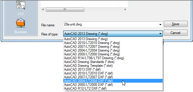
In step 3, you can select from the following DXF file formats:
- AutoCAD 2013 DXF
- AutoCAD 2010 DXF (AutoCAD 2010, 2011, and 2012 share file formats)
- AutoCAD 2007/LT 2007 DXF (AutoCAD 2007, 2008, and 2009 share file formats)
- AutoCAD 2004/LT 2004 DXF
- AutoCAD 2000/LT 2000 DXF
- AutoCAD R12/LT2 DXF
Choose the appropriate format for the program to which you’re exporting. In most cases, the safest choice is AutoCAD R12/LT2 DXF if you’re exporting to another CAD program, although AutoCAD won’t maintain the complete functionality of AutoCAD 2014 for such files.
After you’ve selected a DXF format from the Files Of Type drop-down list, you can set more detailed specifications by choosing Tools ⇒ Options in the upper-right corner of the Save Drawing As dialog box. Doing so opens the Saveas Options dialog box. For DXF files, select the DXF Options tab (see Figure 20-9).
Figure 20-9 The Saveas Options dialog box open to the DXF Options tab
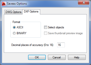
The DXF Options tab contains the following options:
In addition to using the Save Drawing As tool, you can type Dxfout↵ at the Command prompt to open the Save Drawing As dialog box. This is a standard Windows file dialog box that includes the Options button described in the next section.
Opening or Importing DXF Files
Some offices have made the DXF file format their standard for CAD drawings. This is most commonly seen in offices that use a variety of CAD software besides AutoCAD.
AutoCAD can be set up to read and write DXF files instead of the standard DWG file format by default. Here’s how it’s done:
After you do this, all your drawings are automatically saved in the DXF format of your choice.
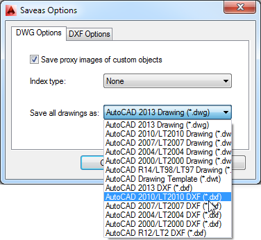
You can also set the default AutoCAD file type by clicking the Tools button in the Save Drawing As dialog box and clicking Options. As you saw in the preceding section, the Saveas Options dialog box includes the DWG Options tab (see Figure 20-10). You can select a default file type from the Save All Drawings As drop-down list.
Figure 20-10 The Saveas Options dialog box open to the DWG Options tab
If you need to open a DXF file only once in a while, you can do so by selecting DXF from the Files Of Type drop-down list in the Select File dialog box. This is the dialog box you see when you click Open from the Quick Access toolbar. You can also use the Dxfin command:
If you want to import a DXF file into the current drawing, you can use the Insert dialog box. (Click Insert on the Home tab’s Block panel.) Click the Browse button to locate and select a file. Make sure the Files Of Type option is set to DXF.
Using AutoCAD Drawings in Page Layout Programs
As you probably know, AutoCAD is a natural for creating line art, and because of its popularity, most page layout programs are designed to import AutoCAD drawings in one form or another. Those of you who employ page layout software to generate user manuals or other technical documents will probably want to use AutoCAD drawings in your work. In this section, you’ll examine ways to output AutoCAD drawings to formats that most page layout programs can accept.
You can export AutoCAD files to page layout software formats in two ways: by using raster export and by using vector file export.
Exporting Raster Files
In some cases, you may need only a rough image of your AutoCAD drawing. You can export your drawing as a raster file that can be read in virtually any page layout or word processing program. To do this, you need to use the PublishToWebJPG.pc3 or PublishToWebPNG.pc3 printer option that comes with AutoCAD, as shown in these steps:
If you don’t see a “paper size” you want to use, you can create a custom size using the Properties button in the Plot dialog box:
Figure 20-11 Editing the plotter configuration
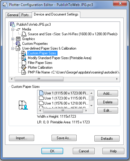
You can edit these settings at any time by opening the PC3 file in the AppDataRoamingAutodeskAutoCAD 2014R19.1enuPlotters subfolder of your profile folder. You can access this file through Windows Explorer or from AutoCAD by clicking Plotter Manager in the Output tab’s Plot panel.
To create a raster file version of your drawing, click Plot on the Quick Access toolbar. Then, in the Plot dialog box select your raster file plotter configuration from the Name drop-down list of the Printer/Plotter group. You can then proceed to plot your drawing, but instead of paper output, you’ll get a raster file. You can specify the filename and location when you click the OK button to plot the file.
If you need to make changes to your raster file configuration, click Plotter Manager in the Output tab’s Plot panel. Then, in the Plotters window double-click your raster file configuration file. You’ll see the same Plotter Configuration Editor you used to set up the raster plotter configuration.
You can set up a different plotter configuration for each type of raster file you use. You can also set up plotter configurations for different resolutions if you choose. To learn more about plotting in general, see Chapter 8, “Introducing Printing, Plotting, and Layouts.” Bonus Chapter 3, “Hardware and Software Tips,” provides detailed information on the Plotter Configuration Editor.
Exporting Vector Files
If you need to preserve the accuracy of your drawing, or if you want to take advantage of TrueType or PostScript fonts, you can use the DXF, Windows Metafile (WMF), or PostScript vector format. You can also export to DGN and SAT file formats. Intergraph’s DGN format is popular in civil engineering, mapping, and other CAD applications. SAT is a 3D modeling format associated with ACIS.
For vector format files, DXF is the easiest to work with, and with TrueType support, DXF can preserve font information between AutoCAD and page layout programs that support the DXF format. The WMF format is also a commonly accepted file format for vector information, and it preserves TrueType fonts and lineweights used in your drawings.
PostScript is a raster/vector hybrid file format that AutoCAD supports. Unfortunately, AutoCAD dropped direct PostScript font support with Release 14. However, you can still use substitute fonts to stand in for PostScript fonts. These substitute fonts are converted to true PostScript fonts when AutoCAD exports the drawing. You don’t see the true results of your PostScript output until you print your drawing on a PostScript printer.
The DXF file export was covered in a previous section of this chapter, so the following sections will concentrate on the WMF and PostScript file formats.
WMF Output
The WMF file type is one of the most popular vector file formats in Windows. It can be opened and edited by most illustration programs, including CorelDRAW and Adobe Illustrator. Most word processing, database, and worksheet programs can also import WMF files. It’s a great option for AutoCAD file export because it preserves TrueType fonts and lineweight settings. You can export WMF files that preserve lineweights as well.
To export WMF files, do the following:
PostScript Output
AutoCAD can export to the Encapsulated PostScript (EPS) file format. If you’re using AutoCAD 2014, you can obtain PostScript output in two ways: You can choose Export ⇒ Other Formats from the Application menu, or you can enter Psout↵ at the Command prompt. If you choose Export ⇒ Other Formats, you can use the Files Of Type drop-down list in the Export Data dialog box to select Encapsulated PS. Another method is to install a PostScript printer driver and plot your drawing to an EPS file. If you’re an AutoCAD LT user, you can’t export to EPS by clicking Export; you must set up a PostScript plotter and use it to plot to a file.
To set up AutoCAD to plot your drawing to an EPS file, follow these steps:
AutoCAD doesn’t preserve font information when creating EPS files from the printer option. It also produces larger files, especially if your drawing contains a lot of area fills and filled fonts. As an alternative to EPS, you can “plot” to an Adobe PDF file. EPS files can often be replaced by PDF files. When you get to the Plotter Model screen, select the Autodesk ePlot (PDF) option from the Manufacturers list. You can also use the full version of Adobe Acrobat or Acrobat Professional to produce PDF files from AutoCAD.
The HPGL plot-file format is another vector format you can use to export your AutoCAD drawings. Use the method described earlier in the section “Exporting Raster Files” to add the HPGL plotter driver to your printer/plotter configuration.
Using OLE to Import Data
To import data from other applications, you use the Cut and Paste features found in virtually all Windows programs. You cut the data from the source document and then paste it into AutoCAD. Typically, you’ll want to paste data into AutoCAD in its native object format, but if you prefer, you can use a Windows feature called Object Linking and Embedding (OLE) to import files.
When you paste data into your AutoCAD file using OLE, you can link it to the source file or you can embed it. If you link it to the source file, the pasted data is updated whenever the source file is modified. This is similar to an AutoCAD Xref file. (See Chapter 15, “Advanced Editing and Organizing,” for more on Xref files.) If you embed data, you’re pasting it into AutoCAD without linking it. You can still open the application associated with the data by double-clicking it, but the data is no longer associated with the source file. Importing files using OLE is similar to other cut-and-paste operations. First, cut the data from the source application. This could be Microsoft Excel or Word. In AutoCAD, click Paste Special from the Paste flyout on the Home tab’s Clipboard panel to open the Paste Special dialog box (see Figure 20-12).
Figure 20-12 Use Paste Special to link your data.
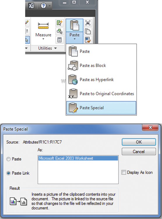
Click the Paste Link radio button to tell AutoCAD that you want this paste to be a link. Notice that the list of source types changes to show only one option. This option will depend on the source document. Click OK. You’re prompted to select an insertion point. Place the cursor in the location for the paste, and click. The imported data appears within the drawing. Depending on the type of data, it may appear in a bounding box. You can adjust the size of the bounding box to fit the scale of the drawing.
In addition to using the Paste Special tool, you can import an OLE object by clicking OLE Object in the Insert tab’s Data panel to open the Insert Object dialog box (see Figure 20-13).
Figure 20-13 Inserting a new object
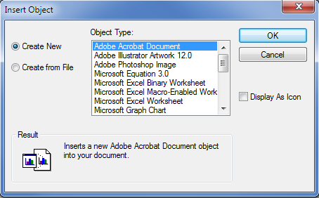
You can then select the type of object you want to import from the Object Type list box. Two radio buttons to the left of the list box let you import an existing object or create a new object of the type listed in the list box. If you choose the Create New radio button, the application associated with the object type will start and open a new file. If you choose the Create From File radio button (see Figure 20-14), the dialog box changes to show a filename and a Browse button.
Figure 20-14 Inserting an existing object
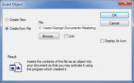
You can then browse for an existing file to import. The Link check box lets you specify whether the imported file is to be linked and needs to be selected in order to use the Olelinks command described in the next section.
Editing OLE Links
After you’ve pasted an object with links, you can control the links by typing Olelinks↵ at the Command prompt. If there are no linked objects in the drawing, the Olelinks command does nothing; otherwise it opens the Links dialog box (see Figure 20-15).
Figure 20-15 Editing links
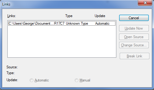
The options available in the Links dialog box are as follows:
Importing Worksheets as AutoCAD Tables
Although it can be beneficial to import worksheets as linked OLE objects, you may prefer to import worksheets as AutoCAD entities. You may not need the direct link to the source material that OLE linking offers. The ability to edit the imported worksheet directly in AutoCAD may have a higher priority for you.
In Chapter 11, you saw how you can create tables in AutoCAD by using the Table tool. You can import an Excel worksheet as an AutoCAD table by using the AutoCAD Entities option in the Paste Special dialog box. By importing worksheets as tables, you have more control over the layout and appearance of the worksheet data.
Try the following exercise to see how you can create a table from a worksheet:
Figure 20-16 The Excel worksheet
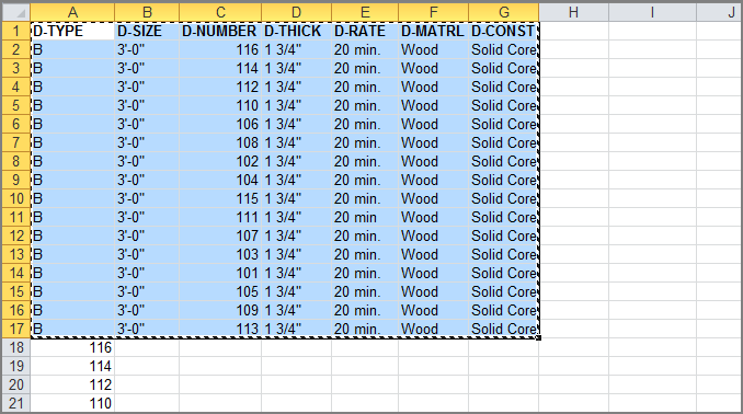
Figure 20-17 The Paste Special tool
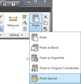
Figure 20-18 Scale and size the table.
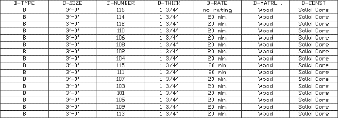
You can edit this imported worksheet using the editing methods for AutoCAD tables described in Chapter 11. In that chapter, you learned that you could edit the text format, the border lineweight and color, and the background of cells. You can add rows and columns and rotate text so that it fits more uniformly in a vertical column.
In this exercise, the worksheet was imported using the default standard table style. This gives you a simple-looking table using the AutoCAD TXT font. You can set up a custom table style with the fonts and borders you want and then import the table for a more custom appearance. Make sure your custom table style is the current style before you import the worksheet.
Understanding Options for Embedding Data
The Paste Special dialog box offers several other options that may better suit your needs. Here is a brief description of each format that is available:
The options you see in the Paste Special dialog box depend on the type of data being imported. You saw how the Microsoft Excel Worksheet option maintains the imported data as an Excel worksheet. If the contents of the Clipboard come from another program, you’re offered that program as a choice in place of Excel.
Using the Clipboard to Export AutoCAD Drawings
Just as you can cut and paste data into AutoCAD from applications that support OLE, you can cut entities from AutoCAD and paste them as images to other applications. This can be useful as a way of including AutoCAD illustrations in word processing documents, worksheets, or page layout program documents. It can also be useful in creating background images for visualization programs such as Autodesk® 3ds Max® and 3ds Max® Design and for paint programs such as Corel Painter.
If you cut and paste an AutoCAD drawing to another file by using OLE and then send the file to someone using another computer, they must also have AutoCAD installed before they can edit the pasted AutoCAD drawing.
The receiving application doesn’t need to support OLE, but if it does, the exported drawing can be edited with AutoCAD and will maintain its accuracy as a CAD drawing. Otherwise, the AutoCAD image will be converted to a bitmap graphic.
To use the Clipboard to export an object or a set of objects from an AutoCAD drawing, click Copy Clip from the Home tab’s Clipboard panel. You’re then prompted to select the objects you want to export. If you want to export and erase objects simultaneously from AutoCAD, click Cut from the Home tab’s Clipboard panel.
In the receiving application, choose Edit ⇒ Paste Special. You’ll see a dialog box similar to the Paste Special dialog box in AutoCAD. Select the method for pasting your AutoCAD image, and then click OK. If the receiving application doesn’t have a Paste Special option, choose Edit ⇒ Paste. The receiving application converts the image into a format it can accept.