
Chapter 23
Rendering 3D Drawings
In this chapter, you’ll learn how to use rendering tools in the Autodesk® AutoCAD® software to produce rendered still images of your 3D models. With these tools, you can add materials, control lighting, and even add landscaping and people to your models. You also have control over the reflectance and transparency of objects, and you can add bitmap backgrounds to help set the mood.

AutoCAD LT® 2014 doesn’t support any of the features described in this chapter.
In this chapter, you will learn to:
- Simulate the sun
- Use materials
- Create effects using materials and lights
- Apply and adjust texture maps
- Understand the rendering options
- Add cameras for better view control
- Print your renderings
- Simulate natural light
Testing the Waters
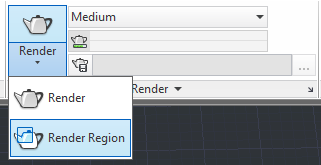
Before we get into the main exercise in this chapter, let’s first take a peek at what’s possible with the AutoCAD rendering tools. This exercise will give you a chance to see how you can quickly obtain a rendered view of a 3D model and how easily you can add materials to objects.
The first file that you’ll work with in this section is simply a collection of primitive shapes in a random arrangement. You’ll use the Render command to view the file without any materials, and then you’ll add a few materials to get familiar with the Materials Browser and see how it can be used to create a more lifelike rendering. Start by opening a sample file and render it as is.
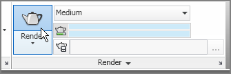
Figure 23-1 The Materials Browser tool and the Render tool
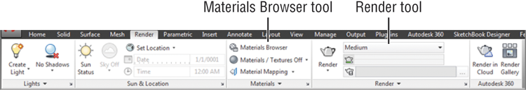
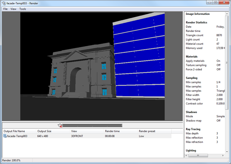
Figure 23-2 The Render window with the rendered view
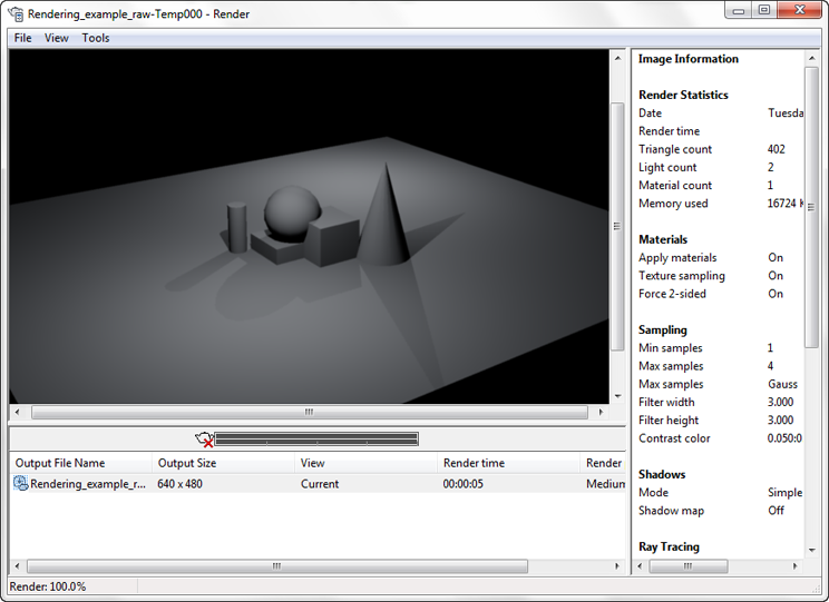
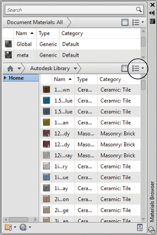
All of the objects in the view are rendered using the default Global material. You can see a sample of this material at the top of the Materials Browser (see Figure 23-3).
Now try adding a material to the sphere:
Figure 23-3 The Materials Browser
You now see that the sphere appears to be made of polished brass in the rendered view. In this exercise, you applied a material by clicking and dragging it to an object.
Now add a few more materials using a slightly different method:
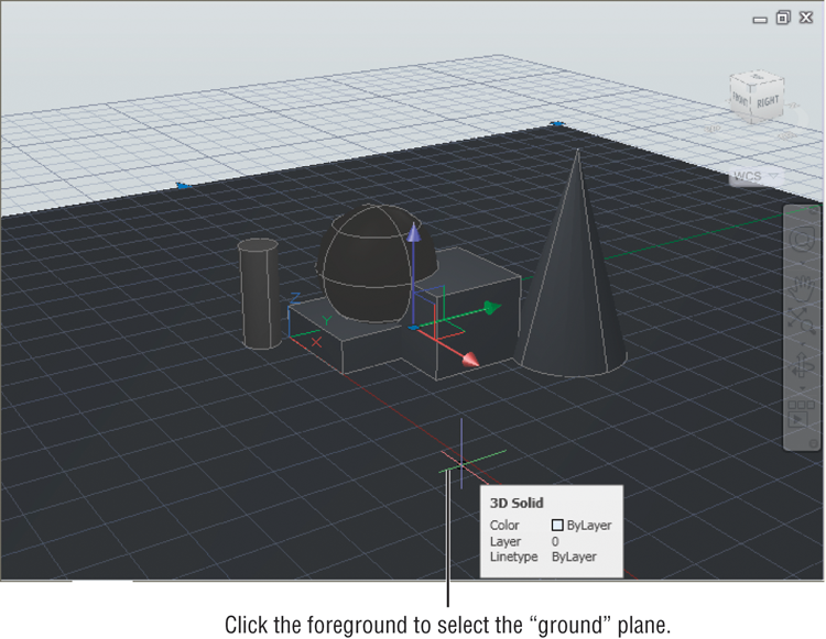
Figure 23-4 Click the foreground surface to select it.
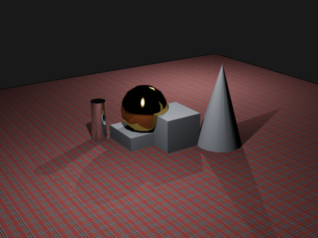
After rendering the view in step 8, you should see the Plaid 1 material of the foreground reflected in the brass sphere and chrome cylinder (see Figure 23-5). The added materials give the rendered view a more realistic appearance.
This brief introduction to materials and rendering shows you some of the potential of these tools. In the rest of the chapter, you’ll get an in-depth view of the many ways you can control the appearance of rendered views from your 3D models.
Figure 23-5 The rendered view with additional materials
Creating a Quick Study Rendering
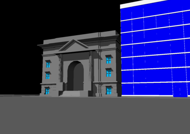
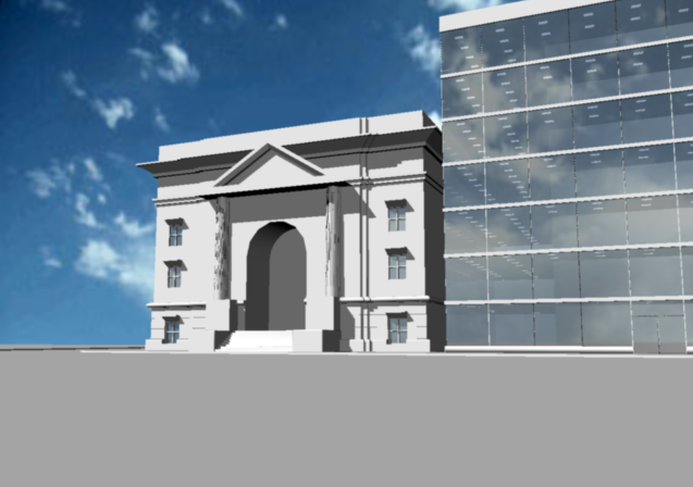
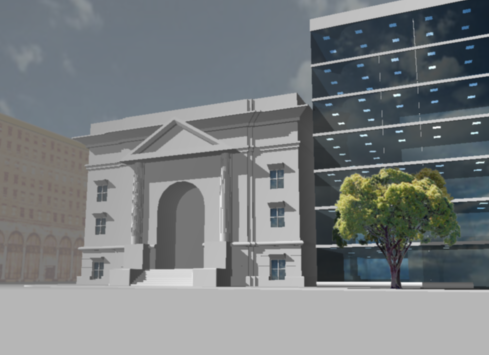
Throughout the rest of this chapter, you’ll work with a 3D model that was created using the 3D modeling tools. The model is of two buildings on a street corner. You’ll start by using the default rendering settings to get a quick view of what you have at the start:
The Render window displays the render settings in a column to the right. At the bottom of the window, you see the name that AutoCAD gives to the rendering as well as the rendering resolution in pixels, the time it took, and the preset that was used for the rendering. You’ll learn more about these options later in this chapter.
Figure 23-6 The Render window with the facade drawing
Simulating the Sun
AutoCAD allows you to create several types of light sources. If you don’t add a light source, AutoCAD uses a default lighting source that has no particular direction or characteristic. The rendering you just did uses the default lighting to show your model.
You can add a point light that behaves like a lightbulb, a spotlight, or a directed light that behaves like a distant light source such as the sun. AutoCAD also offers a sunlight option that can be set for the time of the year and the hour of the day. This sunlight option is especially important for shadow studies in architectural models.
Setting Up the Sun
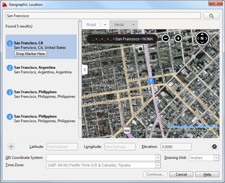
Let’s add the sun to the model to give a better sense of the building’s form and relationship to its site. Setting the location will require you to be logged in to your Autodesk 360 account in order to use the Autodesk Maps Service. Log in by clicking the Sign In button in the information center at the top of the screen. If you don’t have an account, you can create one for free. Let’s make sure the sun is set up for your location:
Figure 23-7 The tools available on the Render tab
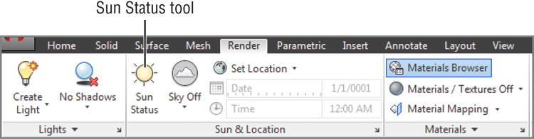
Figure 23-8 Click the Set Location tool in the Sun & Location panel.
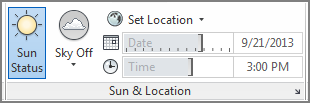
Figure 23-9 Choose your location.
Next, you need to set the date and time of day for the rendering. Once you’ve set the location, you can enter information about the sun’s location in the sky. The sun’s location is dependent on the time of year and the time of day you wish to simulate. Follow these steps:
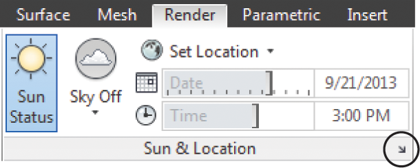
Figure 23-10 Select the time from the drop-down list.
Figure 23-11 The rendering with the sun turned on
Now that you’ve added the sun, you can see the shadows that the sunlight casts. You can turn off the shadows for the sun if you prefer, but they’re on by default.
Setting Polar North
If you’re including the sun as a light source in a drawing in order to run shade studies, it’s essential to orient your drawing accurately. To set the direction of polar north in your drawing, you have to do so when setting up the geographic location. If you need to change where north is, you will have to reset the geographic location. Click Geolocation ⇒ Location ⇒ Edit Location ⇒ From Map. Go through the process of finding your location and inserting the proper coordinates as you did in the previous exercise. The last step of this process is where you will be able to set the north direction (see Figure 23-12).
Figure 23-12 Set the north direction by entering the angle.
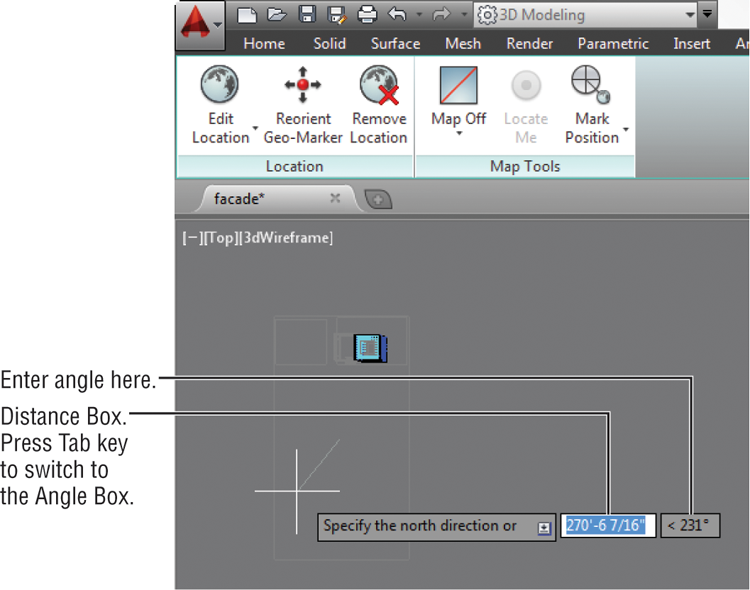
By using this setting, you can set polar north in one of the following ways:
- Directly in the dynamic input box or on the command line, enter a value that indicates an angle away from the horizon line. A positive value sets north counterclockwise from the right side of your screen, whereas a negative value sets it clockwise.
- With Dynamic Input on, press the Tab key to adjust the angle. Use your cursor to indicate the direction based on the insertion point.
Adding a Distant Light
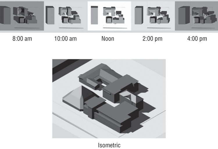
The rendering gives you a fairly accurate idea of how the shadows will fall. This may be all you need if you’re doing a shadow study. For example, you can render a plan view of a 3D model to see where the shadow will fall on a street or a neighboring building, as shown in Figure 23-13.
Figure 23-13 A series of simple renderings showing the way shadows fall from a set of buildings
But the current rendering needs more attention in order to show the building detail. One problem is that the shadows are too dark and hide some of the building’s features. To bring out those features, you’ll add ambient light.
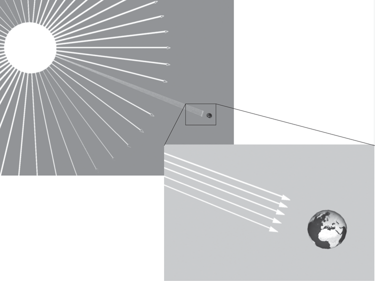
In the real world, a good deal of light is reflected from the ground. You can simulate that reflected light by adding a distant light that shines from below the model. A distant light is like a cross between a point light and a spotlight. The sun is a point source of light, but it’s so far away that its rays are essentially parallel (see Figure 23-14). A distant light behaves in a similar way. It has a point location, yet its light rays are parallel.
Figure 23-14 A distant light is a source whose light rays are parallel, much like the sun’s rays.
A distant light pointing up and toward the buildings can simulate reflected light from the ground; in the following set of exercises, you’ll add a directed light to do just that. In the process, you’ll see how you can quickly switch from a single view to a multiviewport view using tools in the View tab’s Viewports panel:
Figure 23-15 The Left option on the Views flyout
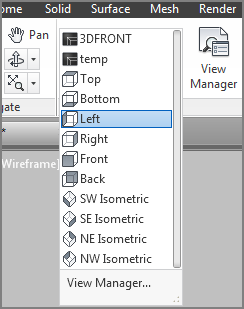
Figure 23-16 Select Distant from the Create Light flyout.
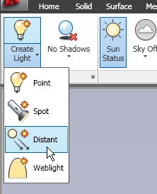
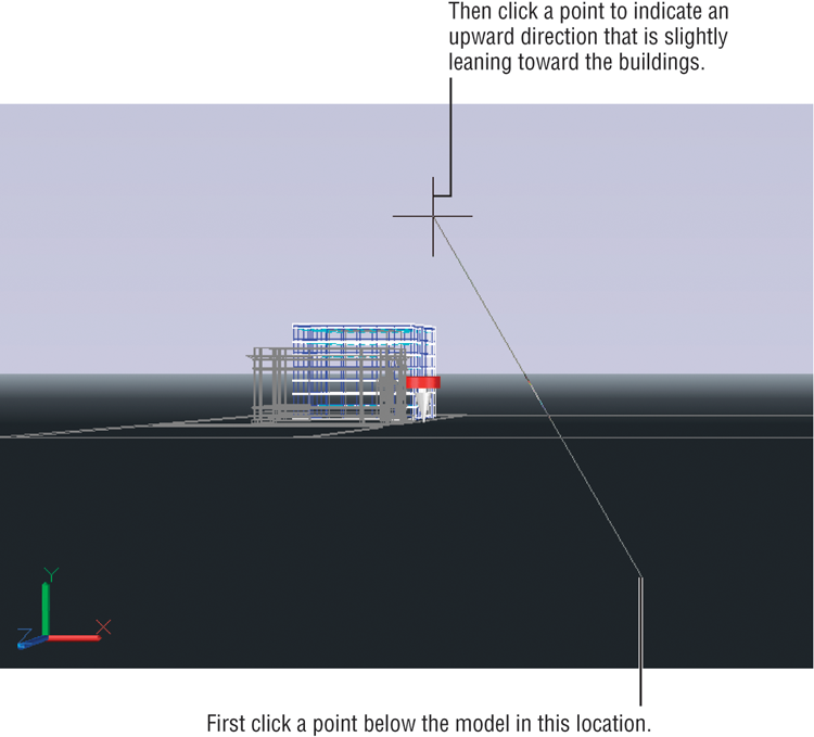
Figure 23-17 Add the distant light as shown in the lower-left viewport.
In step 1, you were directed to select Left from the Views flyout. You could also arrive at the left-side view by using the ViewCube®. The difference is that the Views flyout option also changes the UCS to the plane of the left view, allowing you to place the distant light in the appropriate orientation. In fact, all the orthogonal view options on the Views flyout will change the UCS to the plane of the view. The ViewCube does not affect the UCS.
Now that you’ve added the distant light, go back to the view you want to render. To do so, follow these steps:
You’ve just added a distant light, and even though it isn’t visible, you can access it through the Lights In Model tool. In the next exercise, you’ll see how you can control the intensity of the distant light through the Lights In Model tool:
Figure 23-18 Click the Lights In Model tool to open the Lights In Model palette.
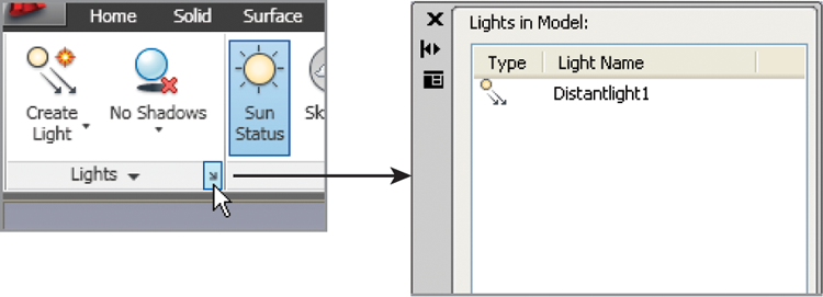
Figure 23-19 The model rendered with the distant light added
Using Materials
The rendering methods you’ve learned so far can be of enormous help in your design effort. Simply being able to see how the sun affects your design can help sell your ideas or move plans through a tough planning-board review. But the look of the building is still somewhat cartoonish. You can further enhance the rendering by adding materials to the objects in your model.
Adjusting the Global Material
AutoCAD uses a default material, called Global, for objects in a drawing that don’t have a specific material assigned to them. The Global material is just like other materials you could use in your drawing, but it’s set up in a way that is as generic as possible to produce simple renderings. For example, the Global material uses the object’s color to determine the rendered color.
As an introduction to materials, try the following exercise. You’ll change the Global material so that it applies a specific color to objects when they’re rendered rather than relying on the object’s color:
Figure 23-20 Double-click the Global material sample swatch.
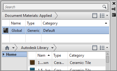
Figure 23-21 The Materials Editor showing a sample image of the Global material
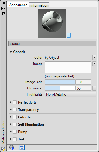
Figure 23-22 Click the flyout icon.
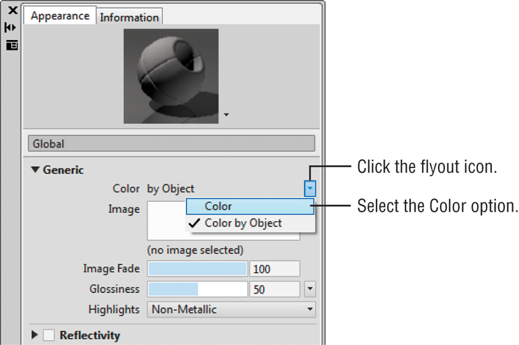
Figure 23-23 Set the Luminance slider to 94.
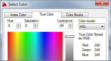
Figure 23-24 Rendering your image in grays
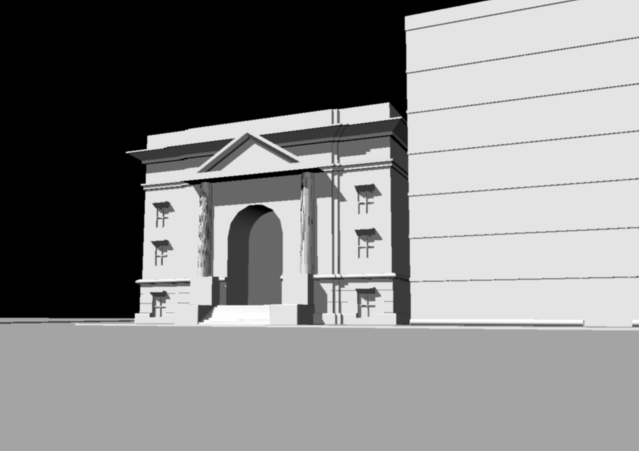
You’ve just changed the color of the global material to off-white. Everything in the model now appears in shades of gray because, so far, the only material in the model is the global one.
Creating a New Material and Changing Its Properties
Two of the most glaring problems in the rendering are the black background and the white glass in the building. You’ll learn how to add a background later. First, you’ll tackle the glass.
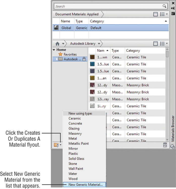
AutoCAD comes with several glass and glazing materials that you could use for this model. However, to get a closer look at how materials work, you’re now going to create a glass material from scratch. This will give you a chance to become familiar with the Materials Editor:
Figure 23-25 The Creates Or Duplicates A Material tool
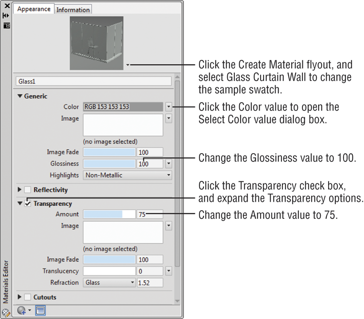
You’ve just created a new material and given it a name. To make this new Glass1 material appear as glass, you need to make some adjustments. You can make a material translucent or transparent, give it color, and even have it glow with self-illumination. You’ll start by giving your new material a set of predefined values that will provide the basis for your glass:
Figure 23-26 The settings for your new Glass1 material
You’ve set up your material. The next step is to apply it to the glass in the model. You might have noticed that when you created the Glass1 material, its sample image appeared in the Materials Browser. You can now add this material to objects in your model just as you did in the first exercise in this chapter.
To add the Glass1 material to the glass curtain wall of the building, do the following:
Figure 23-27 Selecting the glass
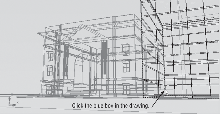
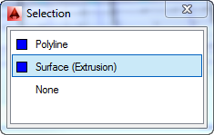
Figure 23-28 Selecting Surface (Extrusion) in the Selection dialog box
Adding a Background
You may have noticed the Reflectivity option in the Materials Editor and guessed that it lets you set how much of the surrounding scene a material will reflect. In this next exercise, you’ll add a background to the model and turn on the Reflectivity option for the glass to add a bit more realism to the rendered view:
Figure 23-29 Select View Manager from the Views panel.
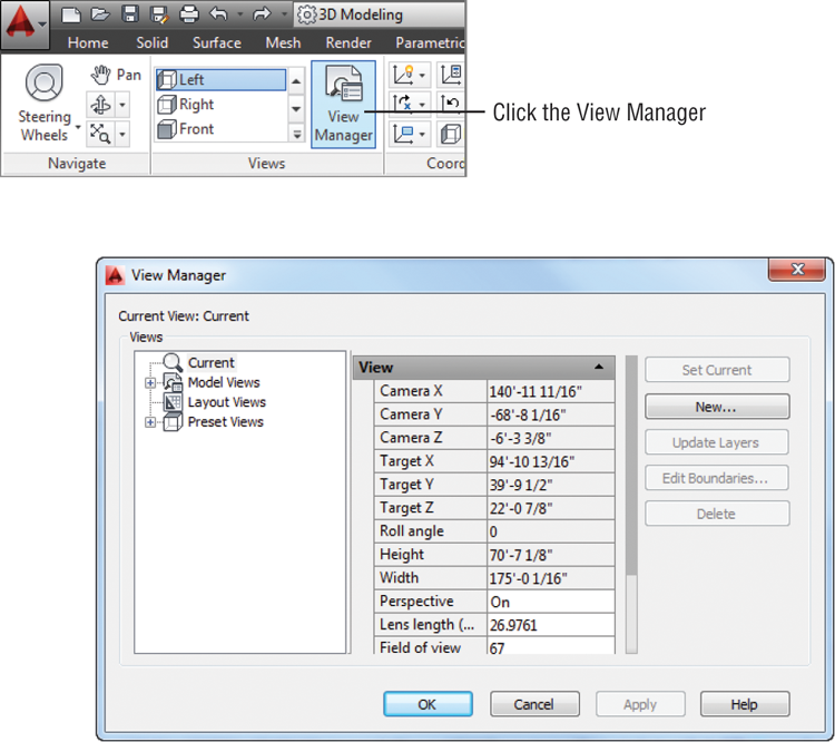
Figure 23-30 The New View / Shot Properties dialog box
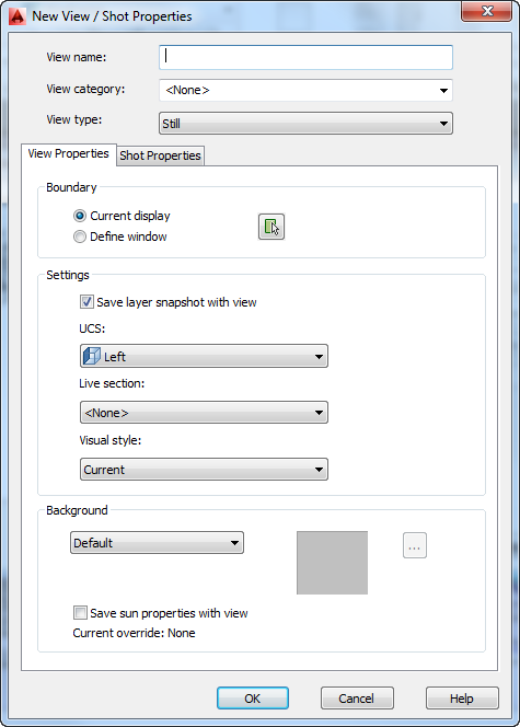
Figure 23-31 Choose your background image.
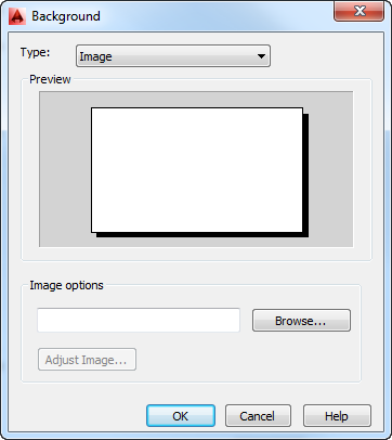
Figure 23-32 Size and position your background.
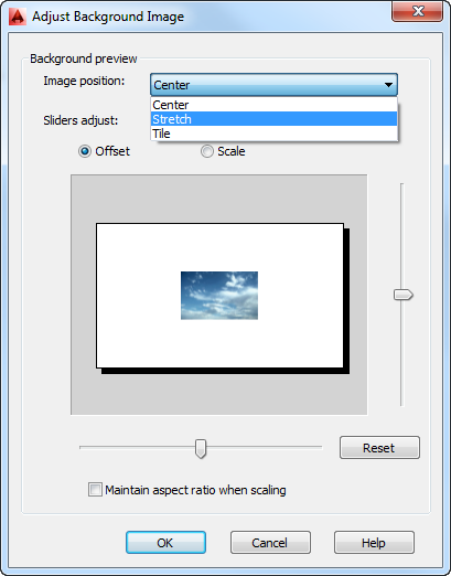
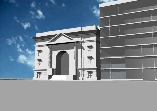
Figure 23-33 The rendered model with a background added
Next, turn on the Reflectivity option for your Glass1 material to have the glass reflect the background that you have just added:
Figure 23-34 The Reflectivity option
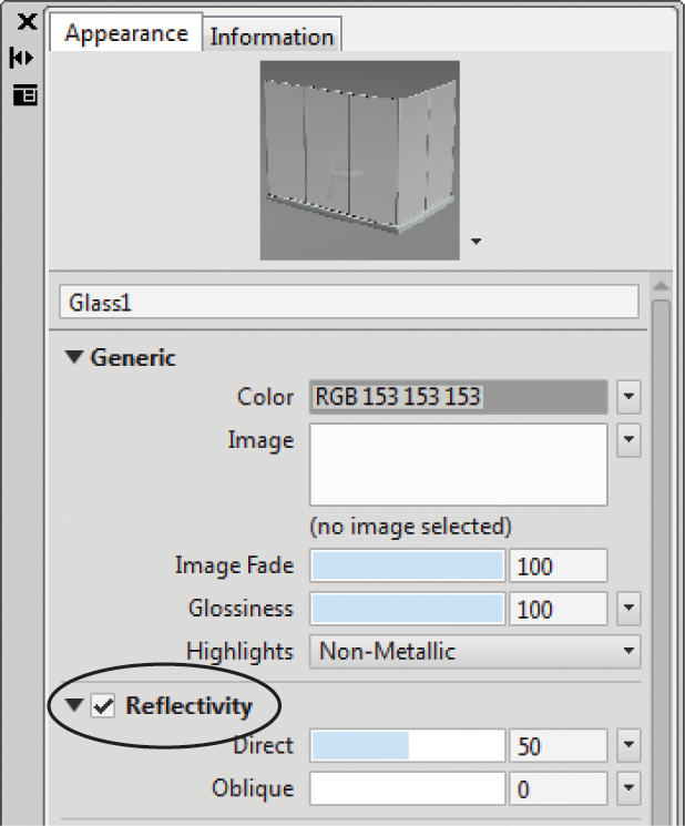
Figure 23-35 The model rendered with the Glass1 Reflectivity setting turned on

As you can see, the glass now reflects the sky background, creating a more realistic appearance. The Direct setting adjusts how much of the surrounding scene the glass reflects when your view is directly in front of the surface. The Oblique setting lets you control the reflection when your view is at a steeper angle to the surface.
Creating Effects Using Materials and Lights
Up to now, you’ve used only two light sources: a distant light and the sun. Two other light sources are available to help simulate light: point-light sources and spotlights. The following sections will show you some examples of how to use these types of light sources—along with some imagination—to perform any number of visual tricks.
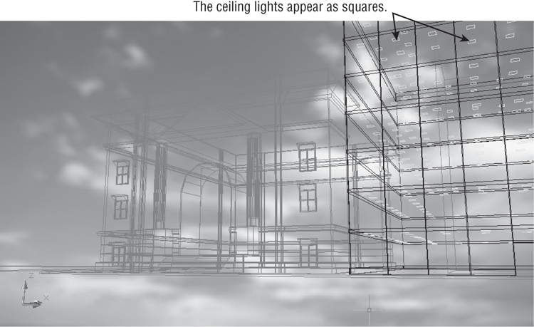
The office building on the right half of the rendering is still a bit cold looking. It’s missing a sense of activity. You may notice that when you look at glass office buildings, you can frequently see the ceiling lights from the exterior of the building—provided the glass isn’t too dark. In a subtle way, those lights lend a sense of life to a building.
Adding a Self-Illuminated Material
To help improve the image, you’ll add some ceiling lights to the office building. We’ve already supplied the lights in the form of square 3D faces arrayed just at the ceiling level of each floor, as shown in Figure 23-36. In this section, you’ll learn how to make the ceiling lights appear illuminated.
Figure 23-36 The 3D Face squares representing ceiling light fixtures
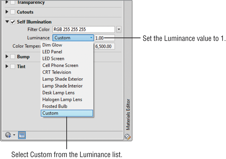
Follow these steps to assign a reflective white material to the ceiling fixtures:
Figure 23-37 Select Custom from the Luminance list.

Assigning Materials by Layer
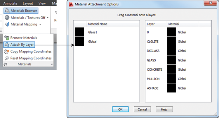
You’ve just created a self-illuminated material. The next step is to assign the material to the ceiling lights in the model. So far, you’ve applied materials to objects one at a time, but it would be too time-consuming to have to select each light individually. You can assign materials to layers, which can save time as long as you’ve organized your model into layers that represent materials.
In the Facade drawing, we’ve already set up some layers for you. The ceiling lights are on a layer called CLGLITE. The next exercise shows you how to apply a material to a layer:
Figure 23-38 Clicking the Attach By Layer tool allows you to assign materials to layers.
In the previous exercise, you created a self-illuminated material that, when assigned to an object, appeared to glow. You then added this material to the ceiling lights in the model. This self-illuminated material doesn’t actually produce light in the model, however. To do that, you’ll have to add light objects such as distant lights or spotlights.
Figure 23-39 The lights appear in the ceilings of the building to the right.
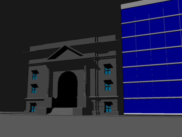
Simulating a Night Scene with Spotlights
Spotlights are lights that can be directed and focused on a specific area. They’re frequently used to provide emphasis and are usually used for interior views or product presentations. In this exercise, you’ll set up a night view of the Facade model by using spotlights to illuminate the facade.
You’ll start by setting up a view to help place the spotlights. You’ll save this view because you’ll be going back to it several times:
Figure 23-40 Select Parallel from the ViewCube’s context menu.
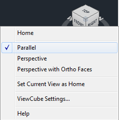
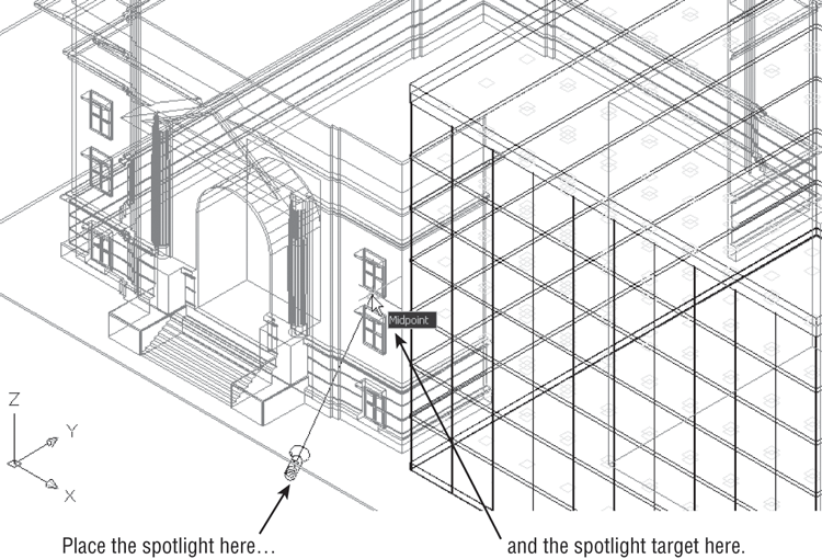
Figure 23-41 Set up your view to look similar to this, and then add the spotlight.
Now you’re ready to add the lights:
Enter an option to change
[Name/Intensity/Status/Hotspot/Falloff/shadoW/Attenuation/Color/eXit] <eXit>:
Figure 23-42 Enter a view name.
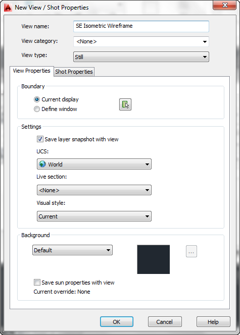
Figure 23-43 Choose Spot from the Create Light flyout.
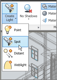
Figure 23-44 Copy the spotlight to this location.
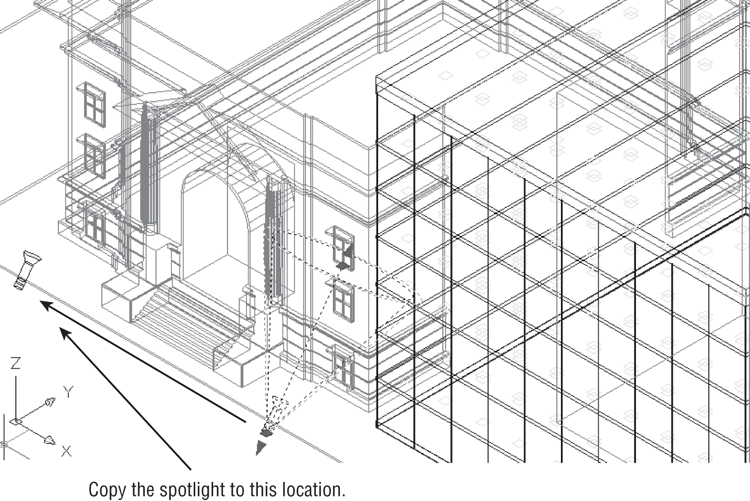
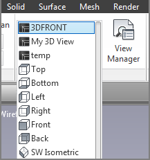
Figure 23-45 Select 3DFRONT from the 3D Navigation drop-down list.
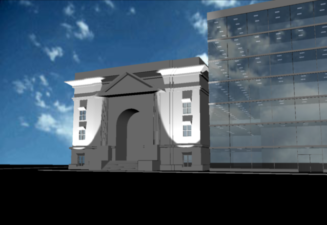
Adding lights to your rendering will enhance it tremendously. Spotlights concentrate the illumination of objects just as a spotlight in the real world would do. Use them as in our exercise to highlight the outside of a building, to brighten up a dark area of a room, or to have an object stand out.
Figure 23-46 The rendered view of the model with the spotlights
Adding a Point Light
A few things still need to be added to improve this rendering. You can adjust the spotlight so that it casts light over a wider area. You can also add a light in the entrance so it isn’t quite so dark. The next section will show you how to make adjustments to your spotlight. First, you’ll add a point light to obtain a different lighting effect:
Figure 23-47 Select the Point tool from the Create Light flyout.
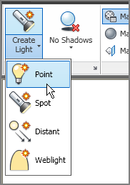
Figure 23-48 Select the center of the arch.
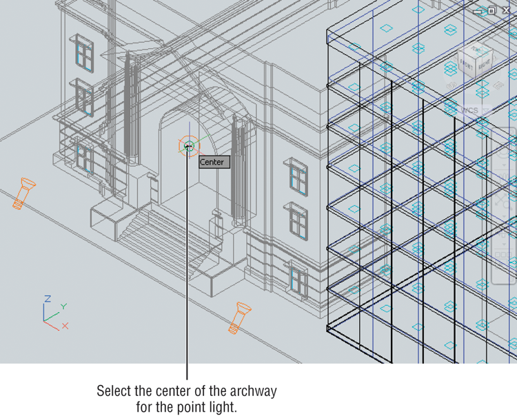
Enter an option to change [Name/Intensity/Status/shadoW/
Attenuation/Color/eXit] <eXit>:A point light doesn’t target an area as a spotlight does. It illuminates everything around it. Placing one here will brighten up the entrance of the building. The glow of the light will look like it is coming from the archway.
Editing Lights
You’ve added the point light. Before you see the results in a rendering, you’ll also change the spread of the spotlights. In this exercise, you’ll edit the properties of the spotlight. Not all lights have the same properties, but the basic process for editing all lights is the same:
Figure 23-49 Adjust the falloff of the spotlight.
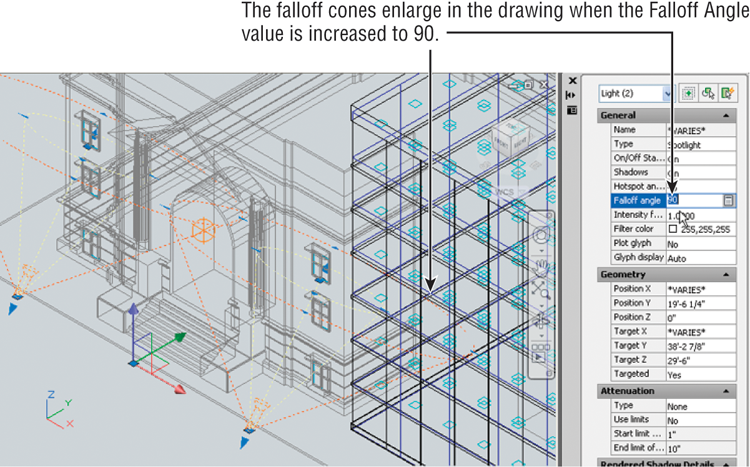
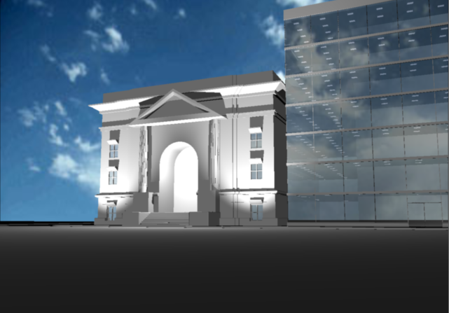
Figure 23-50 The rendered view of the model with the spotlights modified and the point light added
In step 2, you saw a list of options for the spotlight. Many of these options are available when you first insert the light; they appear as command-line options. Often, it’s easier to place the light first and then play with the settings.
In this example, you adjusted the spotlight’s falloff. By increasing the falloff angle, you broadened the spread of the light cast by the spotlight and also made the transition from light to dark appear smoother, as shown in Figure 23-51. The hotspot can also be adjusted to a narrow beam or a wide swath.
Figure 23-51 The hotspot and falloff of a spotlight at the top produce the lighting shown at the bottom.
Many other light properties are available to you in the Properties palette. Table 23-1 describes them.
Table 23-1: Properties available for lights
| Property | What it does | |
| General Properties | ||
| Name | Shows the name of the light | |
| Type | Sets the type of light | |
| On/Off Status | Shows whether light is on or off | |
| Hotspot Angle | Sets the spotlight hotspot angle | |
| Falloff Angle | Sets the spotlight falloff angle | |
| Intensity Factor | Sets the light intensity | |
| Filter Color | Sets the secondary light color simulating a color filter over a lamp | |
| Plot Glyph | Allows the light glyph to be plotted | |
| Glyph Display | Controls the display of the light glyph | |
| Type | Shows the type of attenuation: Inverse Linear, Inverse Square, or None | |
| Use Limits | Lets you turn on attenuation limits | |
| Start Limit Offset | If Use Limits is on, sets the distance to the beginning of attenuation | |
| End Limit Offset | If Use Limits is on, sets the distance to the end of attenuation | |
| Rendered Shadow Details Properties | ||
| Type | Lets you select between Sharp and Soft shadow edges | |
| Map Size | When shadow maps are used, lets you determine the size of the shadow map in pixels | |
| Softness | When shadow maps are used, determines the softness of shadows | |
Applying and Adjusting Texture Maps
You’ve already seen how to assign a material to an object by adding the glass material to the building in the facade.dwg file. You can create other surface textures by using bitmaps in other ways to help enhance your rendering. For example, you can include a photograph of existing buildings that may be in the scene you’re rendering.
Creating a Building from a Box
Figure 23-52 shows a bitmap image that was scanned into the computer and edited using a popular paint program.
Figure 23-52 A bitmap image of a building you’ll use in the model
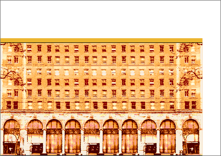
We’ve added some blank white space to the bitmap image of the building so you can get practice fitting an image to an object. Imagine that this building is across the street from the Facade model and you want to include it in the scene to show its relationship to your building. The following exercise will show you how it’s done:
The box you just added represents the building on the next block. Now create the material that you’ll use to give this building some detail:
Figure 23-53 The box representing the building on the next block
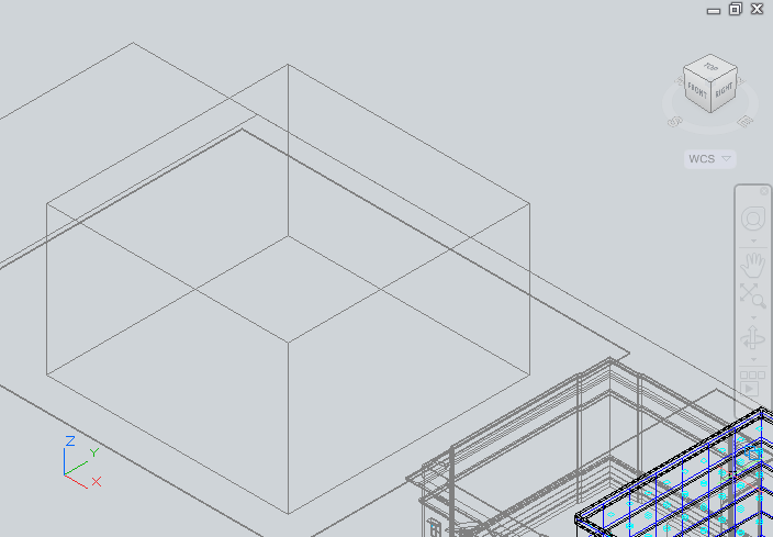
Figure 23-54 The Image flyout
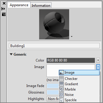
Figure 23-55 The Texture Editor
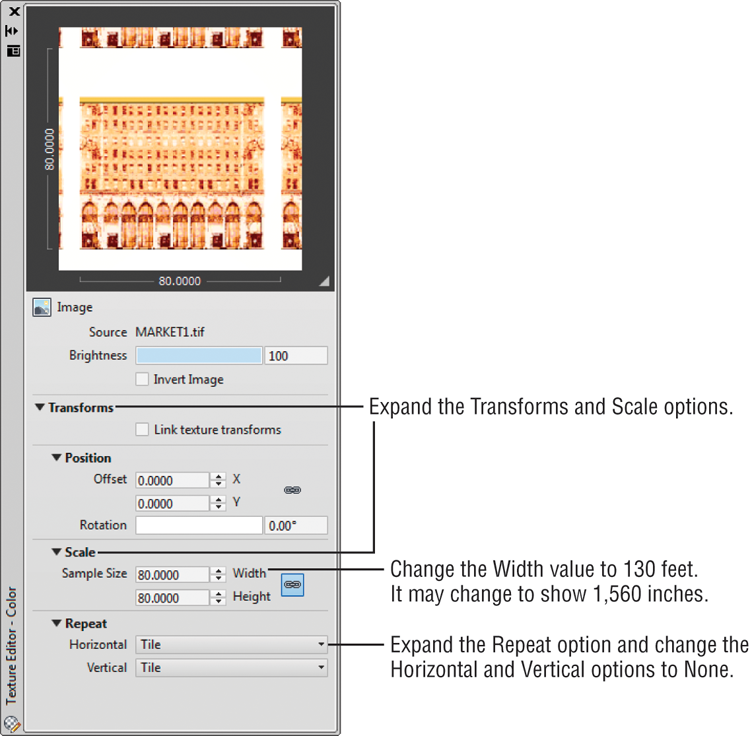
You’ve just set up a material that will apply the MARKET1.tif image to any object in your model. You gave it a size of 130′ (metric users, 49 m) because that is the size of the box representing the building on the next block.
Now continue by adding the material to the box and applying the appropriate mapping style:
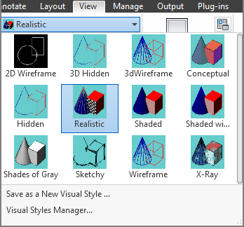
Figure 23-56 Select Realistic from the Visual Styles drop-down list.
Adjusting a Material to Fit an Object
The entire image, including the blank white space, is placed on the box. You even see the image on the rooftop, although you won’t see the rooftop in any of the renderings. (You can hide it with another box or 3D surface if you want an aerial view.) You can adjust the position and scale of the bitmap by using the mapping tools in the Materials panel. The mapping tools make the mapping gizmo visible:
Figure 23-57 Click the Box mapping tool.
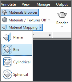
Figure 23-58 The material mapping appears as a yellow outline around the selected box.
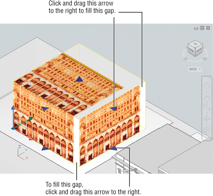
Figure 23-59 The box after adjusting the map
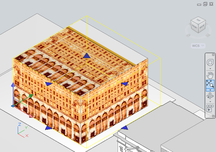
You just added a mapping gizmo to the box and then adjusted the gizmo so that the material fits the box. If you need to make further adjustments to the gizmo, click the Box mapping tool again and click the object you need to adjust.
Now look at the rendered version. First you’ll turn off the spotlights and point light, and then you’ll make sure the sun is on to return to a daylight setting:
You’ve set the lighting for a daylight rendering. Notice that you were able to select several lights to turn them off all at once.
Next, render your view:
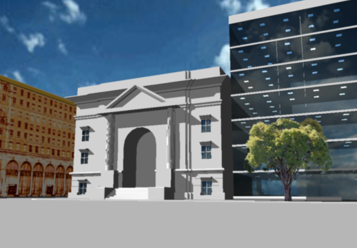
Figure 23-60 The rendering with the new building
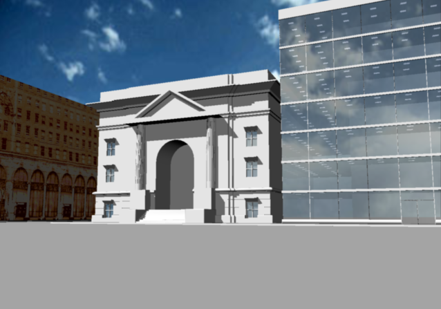
The building is too dark in the shadow. You can lighten it by increasing the Self Illumination setting in the Materials Editor:
Another option is to use a paint program to refine the bitmap image before you use it in AutoCAD. AutoCAD attempts to place the bitmap accurately on a surface, so if the bitmap is fairly clean and doesn’t have any extra blank space around the edges, you can usually place it on an object without having to make any adjustments other than its orientation. We purposely made the spaces in the image so you can practice using the Materialmap feature.
Exploring Your Other Material-Mapping Options
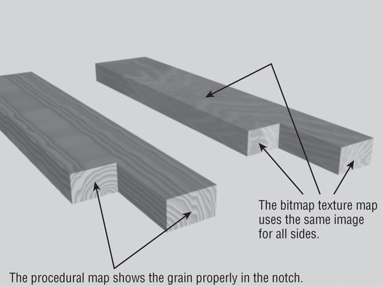
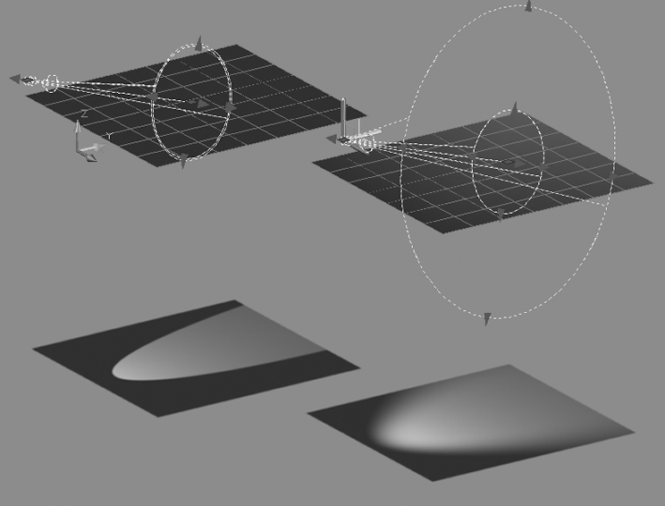
You may have noticed several material-mapping options in the previous exercise. You used the Box option because it was a natural fit for the box you created. But options are offered for a planar surface, a cylinder, and a sphere. Figure 23-61 shows how these other options may be applied to the shapes for which they’re intended.
Figure 23-61 The planar, box, cylinder, and sphere material maps
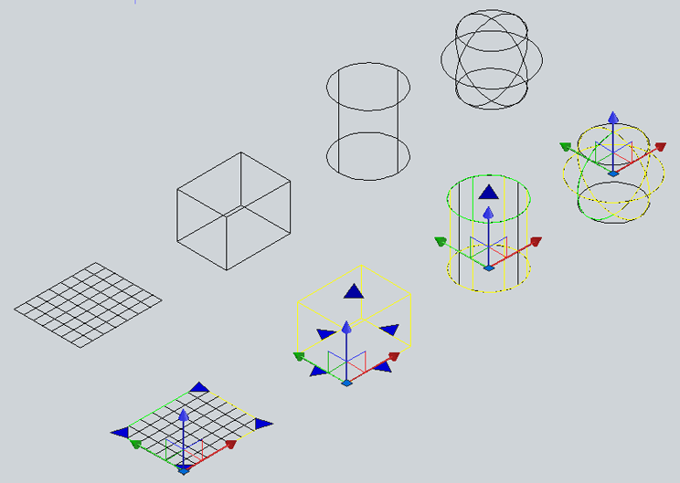
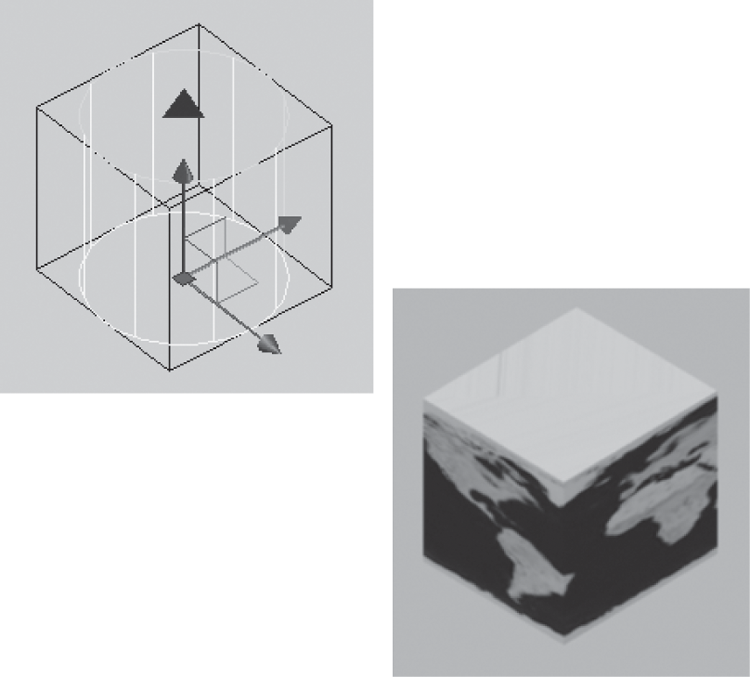
You don’t have to apply the maps to the shapes they describe. Later, you’ll see how you can apply a planar map to a box. You can apply a cylinder map to a thin box to achieve an interesting effect. Also, a spherical map can be applied to a cube (see Figure 23-62).
Figure 23-62 A material map applied to a different shape
Specifying the Size of a Bitmap
As you’ve just seen, the Materialmap feature gives you a quick and intuitive way to set the location of a material map onto an object. There are several other ways to control the appearance of a material on an object. If you have a surface pattern that repeats over the surface, such as a tile pattern, you can set the frequency and size of the pattern. For example, you might have a brick pattern that repeats over a 12′ square area and you want that pattern reproduced accurately on a surface.
Imagine that you need to apply a brick pattern to a wall that is 8′ wide by 4′ tall (approximately 2.4 m by 1.2 m). The blocks are the standard 8″ × 16″ (20.32 cm × 40.64) split-face concrete masonry units, and you have an image that shows four courses of blocks two blocks wide, as shown in Figure 23-63. This is the Masonry.Unit Masonry.CMU.Split-Face.Running.jpg file in the Textures folder that is installed with AutoCAD 2014.
Figure 23-63 The bitmap image of a set of blocks

The following exercise shows you how you can control the size of a material map:
Figure 23-64 The wall with the material applied
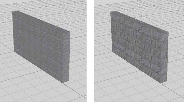
The wall has a concrete block texture. You see the results of a material with the default settings. Although it looks okay, the blocks are too small for the scale of the wall. You need to adjust the bitmap options so the texture appears to the proper scale on the wall object:
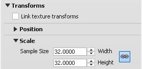
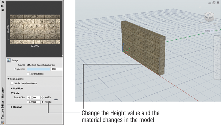
Now, suppose you want the blocks to appear 4″ high instead of 8″ high. You can go back to the Texture Editor and change the Sample Size Height setting to 16 (half the height you specified originally).
Note that to change the width to a value different from the height, you need to click the link icon to the right of the Width and Height input boxes to turn off the link between the height and width values.
The block wall changes to show a 4″ high block, as shown in Figure 23-65.
Figure 23-65 Change the Height setting in the Texture Editor and the wall also changes.
You can use many other settings in the Adjust Bitmap dialog box to fine-tune the appearance of a material over an object. You’ve used the major settings in these exercises.
Simulating Trees and People with Opacity Maps
There’s nothing like adding landscaping and people to a rendering to add a sense of life and scale. Computer images in particular benefit from landscape props because they tend to appear cold and lifeless otherwise.
In the following set of exercises, you’ll create a tree material and apply it to a 3D solid to simulate a tree. In doing so, you’ll get a chance to explore some of the other features of the Materials palette. To create a tree, you’ll use the same image option of the Materials Editor that you’ve been using so far, but you’ll also add something called an opacity map, or cutouts as they are called in AutoCAD.
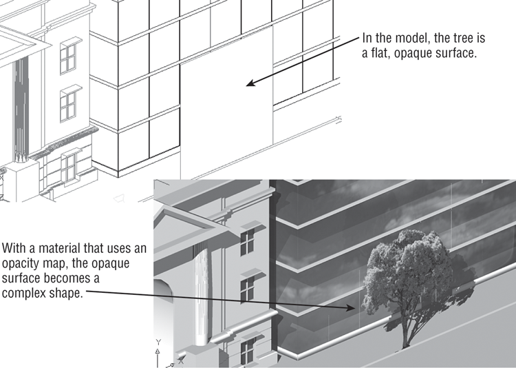
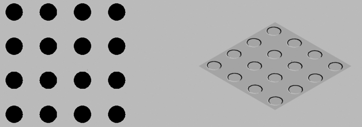
A cutout lets you “cut out” areas of a texture map through a black-and-white image file. For example, in the tree you’ll be creating, you’ll apply a tree material to a simple rectangular region. Since the tree is an irregular shape, you’ll want the area around the tree to be removed, or “cut out,” from the material, creating an illusion of a complex, tree-shaped outline without showing the entire rectangular region.
The opacity map lets you determine which areas are cut out through black-and-white areas of an image. Black areas are cut out, and white areas are opaque. You can use shades of gray to vary transparency. Figure 23-66 shows an example of how an opacity map works.
Figure 23-66 A material using an opacity map can be applied to a 3D solid to create the illusion of a complex outline such as a tree.
In the following exercise, you’ll go back to the Facade model and experiment with opacity maps. To start your tree, create a new material in the Materials palette:
Next, add a texture map of a tree:
Finally, add an opacity map for the tree. The process is basically the same as adding a texture map:
Next, create an object representing a tree in the drawing, and then apply the Tree1 material to the object:
Figure 23-67 Adding a tree
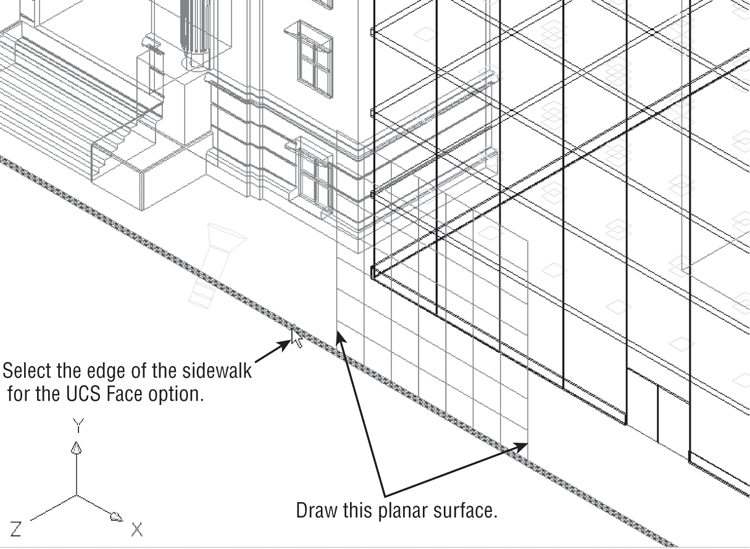
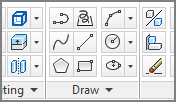
Figure 23-68 The tree added to your rendering
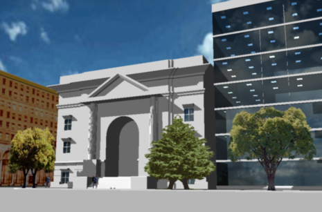
The process of adding people is just the same. You create a material that includes a texture map and an opacity map and then apply the material to a flat box. Make sure you turn on the Fit To Object option in the Adjust Bitmap dialog box for both the texture and the opacity map. Figure 23-69 shows a rendering that includes some additional trees and people.
Figure 23-69 A rendering with more trees and people
Understanding the Rendering Options
Quite a few settings are available to control the quality of your renderings. Take a look at the tools available in the Render tab’s Render panel, shown in Figure 23-70.
Figure 23-70 The expanded Render panel
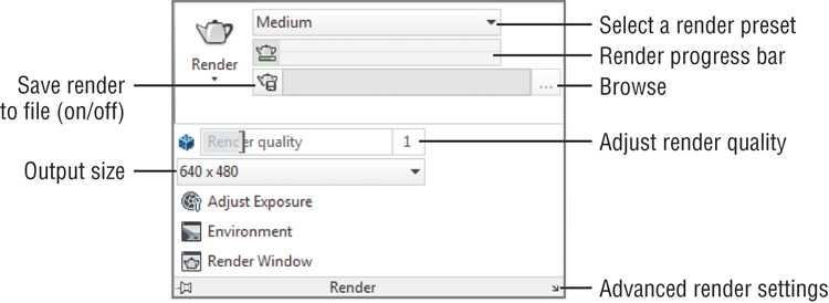
The Save Rendering To File option lets you set up a file to which the renderings will be saved. If you turn on this option, then each time you render your model, the rendering will be saved automatically to the file you designate.
The Render Output Size option lets you set the vertical and horizontal resolution of the rendering in pixels. The default is 640×480. You can choose from a set of predetermined standard sizes or set a custom size.
The Environment option lets you add a fog effect to your rendering (see Figure 23-71). Click this option to open the Render Environment dialog box. This dialog box offers a set of options to control how the fog appears in the rendering. For example, Enable Fog lets you turn the fog effect on or off. Color lets you select a color for the fog. You can experiment with the Render Environment dialog box on your own.
Figure 23-71 The Render Environment option lets you add fog to a rendering.
Render Presets is a drop-down list that gives you a set of options you can use to select the quality of the rendering. The default is Medium, which is the setting you’ve been using. This offers a decent-quality rendering without taking a lot of time. When you want to produce a final, high-quality rendering, select Presentation from this list. The rendering will take longer, but more detail will be brought out. You can also adjust the quality of the rendering with the Render Quality setting. A setting of 0 is the lowest setting where 5 is the highest setting.
Clicking Advanced Render Settings opens the Advanced Render Settings palette. These settings are for the advanced user, and most users won’t need to work with them. Rendering presets are predetermined sets of the advanced render settings. You can make adjustments to these settings if you need to (see “Rendering Interior Views” later in this chapter for more on the advanced render settings).
The Adjust Exposure tool opens the Adjust Rendering Exposure dialog box. Note that a system variable called Lightingunits must be set to 1 or 2 before this option works. The Adjust Rendering Exposure dialog box lets you set the brightness, contrast, and midtones of renderings that use photometric lighting. You’ll see how this works later in this chapter.
Checking and Saving Renderings in the Render Window
All your renderings appear in the Render window, which has a few options you’ll want to know about. At the bottom of the window is a list of all the renderings you’ve done in the current AutoCAD session. If you’ve done several renderings, you can go back to an earlier rendering by clicking it in the list. Right-click an item in the list to display a list of options that you can apply to the selected item. Table 23-2 describes these options.
Table 23-2: Right-click options for image filenames in the Render window
| Option | What it does |
| Render Again | Renders the selected image again. |
| Save | Saves the selected image to a file. AutoCAD offers a choice of monochrome, 8-bit grayscale, 8-bit color, and 24-bit color. You can save your image as a BMP, PCX, TGA, TIFF, JPEG, or PNG file. |
| Save Copy | If you’ve already saved a file once, lets you save it again under a different name. |
| Make Render Settings Current | If you’ve rendered several views and you want to return to the setting of a previous rendering, select the view whose settings you want to restore and select this option. |
| Remove From the List | Removes the selected rendering from the list. |
| Delete Output File | If you’ve saved a rendered view as a file, deletes the file. |
Perhaps the most important of these options are Save and Save Copy. They enable you to keep copies of your rendered views as bitmap images.
If you want to check a detail in the rendering, you can use the Tools menu to zoom in or zoom out of the image. When you zoom in, horizontal and vertical scroll bars are displayed to allow you to pan over the image.
To the right of the window is a listing of the rendering’s statistics. You can make adjustments to many of these settings through system variables and the Advanced Render Settings palette.
Adding Cameras for Better View Control
Throughout this chapter, you’ve seen how you can save and recall views. Views can be real time-savers, especially if you have several views that you save and recall. Views will also save background and visual styles. Typically, you set up a view using the tools you’ve learned about so far, but there’s another tool that can give you that extra level of control you may need for special circumstances: the Camera tool.
What isn’t obvious is that your views are also represented as cameras. Right now, you can’t see the cameras because a setting called Camera Glyph is turned off. Try the following to visualize your My 3D View as a camera:
Figure 23-72 Adding a new camera
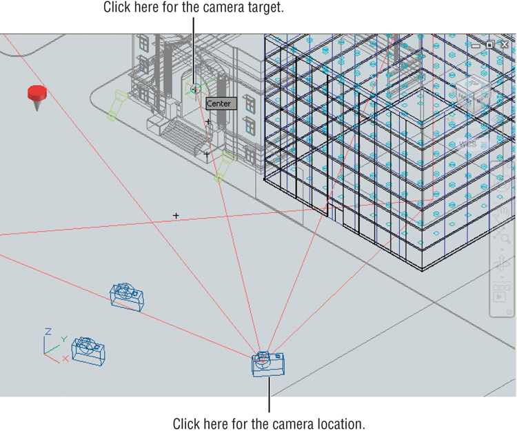
Figure 23-73 Displaying cameras
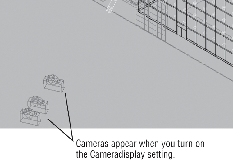
Figure 23-74 Viewing the camera preview
When you select a camera, not only do you see the camera preview, you also see a set of grips for the camera. You’ll get a chance to work with some of those grips a little later. Next, try to create a view using the Camera tool.
The following exercise shows an example of adding a camera to the Facade model. You’ll add a camera, and you’ll apply one of the options available for it:
Current camera settings: Height=0″ Lens Length=50.0000 mm
Specify camera location:Enter an option
[?/Name/LOcation/Height/Target/LEns/Clipping/View/eXit]<eXit>:AutoCAD gives your camera the default name Camera1. You can rename it at any time in the Properties palette or in the View Manager.
You were able to set the height of the camera independent of the location you selected in step 3 by using one of the options in the prompt. Table 23-3 describes the other options that are available.
Table 23-3: Camera prompt options
| Option | What it does |
| ? | Displays a list of cameras in the current drawing |
| Name | Lets you provide a name for your camera (no spaces allowed) |
| LOcation | Lets you change the location of the camera |
| Height | Lets you specify the height of the camera |
| Target | Lets you select a target location |
| LEns | Lets you specify a lens focal length in mm |
| Clipping | Lets you include front and back clipping planes |
| View | Lets you go to the camera’s view |
| eXit | Exits the command |
Making Adjustments to Your Camera
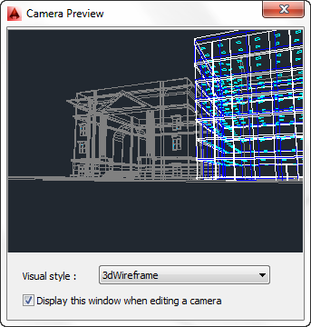
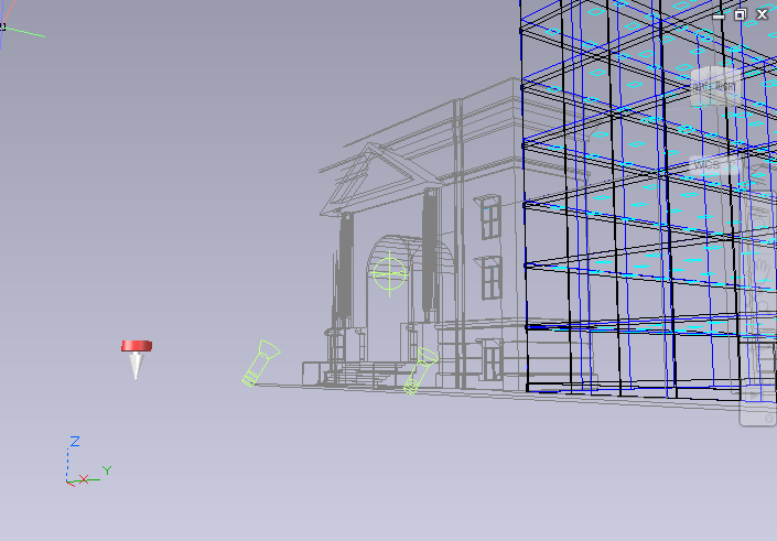
Now that you’ve got the camera in place, you can see what the view looks like. You can use the 3D Navigation drop-down list to display the view from your new camera, or you can click the camera to open the Camera Preview window. Before you do any of that, try making some adjustments to the camera:
Figure 23-75 The Camera Preview dialog box

Now turn on the clipping planes to see how they work:
Figure 23-76 Select the Front And Back On option in the Properties palette.
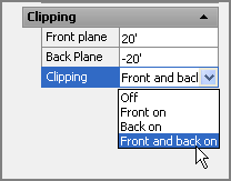
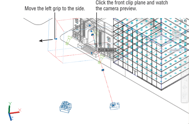
The clipping planes hide objects either behind or in front of the target location. As you’ve just seen, you can indicate the clipping-plane distance from the target in the Properties palette. You can also make adjustments to the clipping plane directly in the drawing using the camera’s grips:
Figure 23-77 Selecting the camera grips
You can adjust the back grip the same way so you can get direct feedback on how much of your view is being clipped.
Next try adjusting one of the other grips:
As you can see in the Properties palette for the camera, you have a number of controls to affect the view. Because cameras and user-created views are basically the same thing, the properties you see for cameras are the same as those you would see for views in the View Manager. (Open the 3D Navigation drop-down list, and select Manage Views at the bottom of the list.) Obviously, the options presented here apply to other views as well.
Let’s see the results of your work: Select Camera1 from the 3D Navigation drop-down list in the Home tab’s View panel. You see the camera view you just set up (see Figure 23-78).
Figure 23-78 The Camera1 view
Creating an Animated Walk-Through
Another feature that is related to the camera is motion path animation, which allows you to create an animated walk-through of your design. Such animations can be a great aid in helping others to visualize your ideas more clearly. Try this exercise:
Figure 23-79 Draw the polyline for the motion path and select the arch center.
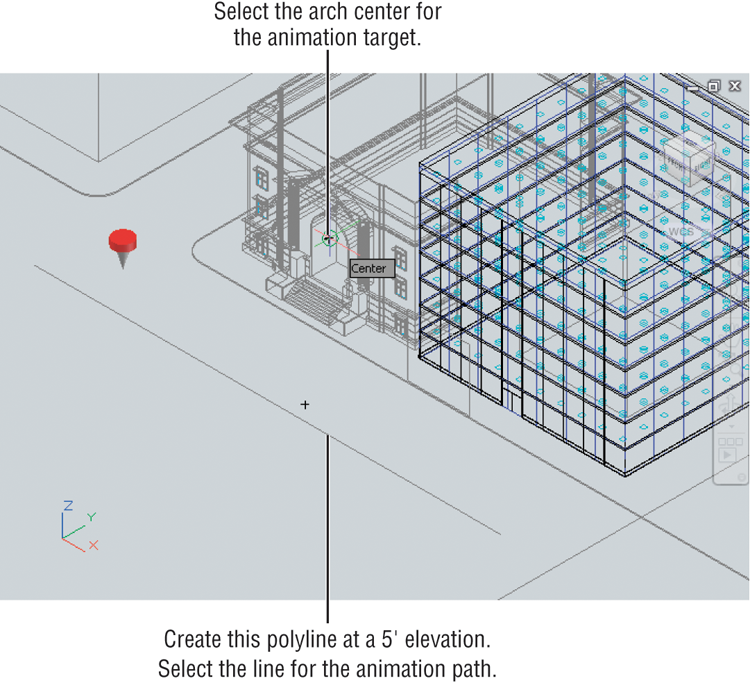

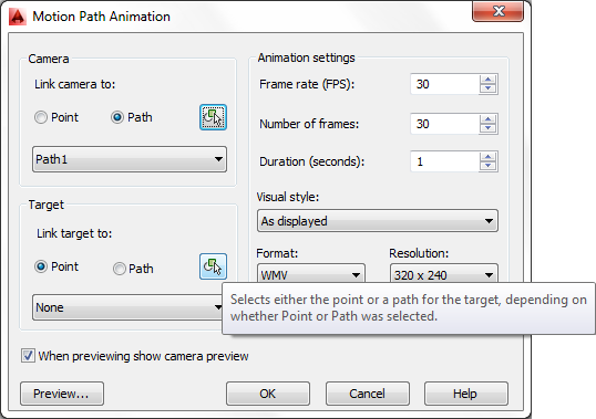
Figure 23-80 The Motion Path Animation dialog
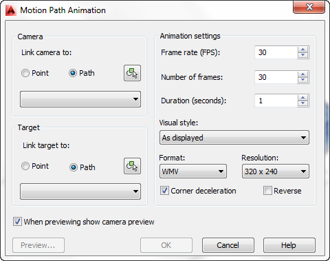
Figure 23-81 Choose the Path option and click the Select Path tool.
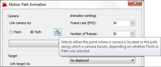
Figure 23-82 Select the Point option and click the Pick Point tool.
You were asked to save the animation even though it was in a fairly crude state and was too fast. The advantage of saving the animation right away is that you then have access to the animation camera.
AutoCAD creates a new camera with default settings when an animation is created. You can then make adjustments to the camera and other animation settings to refine your animation.
Fine-Tuning the Animation
Once you’ve created and saved an animation, no matter how crude, you can edit its camera settings as well as its speed, resolution, and visual style. To get a feel for how to edit an animation, try the following:

This time, AutoCAD takes more time to process the animation because you’ve increased the duration. When it’s done, locate your animation file using Windows Explorer, and double-click it to view the results.
As you saw in step 5, you can use any visual style that is in the drawing. You can even create a fully rendered version of the animation—but be aware that the more complex the animation, the longer AutoCAD will take to process it.
You can also modify the polyline path by adding more segments or changing the location of the path’s vertices.
You’ve seen how a few of the options in the Motion Path Animation dialog box work. If you think you may find this tool useful, you’ll want to experiment with some of the other settings. Table 23-4 describes these options.
Table 23-4: Motion path animation, camera, and target options
| Option | What it does | |
| Camera and Target options | ||
| Point/Path | Selects between a point or a path for the camera or target. | |
| Select Path/Pick Point | Temporarily closes the dialog box to allow you to select a path or a point. | |
| Drop-down list | Lets you choose from a point or a path that has already been selected. | |
| Animation Settings options | ||
| Frame Rate (FPS) | Sets the frame rate in frames per second. The lowest you can go for a smooth animation is 16. TV is usually around 30 fps. | |
| Number Of Frames | Sets the total number of frames in the animation. The lower the number, the faster the animation. This setting is dependent on the Duration and Frame Rate settings. | |
| Duration (Seconds) | Sets the duration of the animation. A typical duration is 10 seconds. | |
| Visual Style | Sets the visual style for the animation. You can also select Rendered for a fully rendered animation. | |
| Format | Lets you choose an animation file format. If you plan to use the Windows Movie Maker application to edit your animation, use WMV. Other options are AVI (Windows), MOV (QuickTime), and MPG (MPEG 1 or 2). | |
| Resolution | Sets the resolution of the animation. 320×240 is typical for computer video and VCD. 640×480 is typical for DVD quality. | |
| Other options | ||
| Corner Deceleration | Automatically decelerates the animation motion at corners for smoother transitions. | |
| Reverse | Reverses the animation. | |
| When Previewing Show Camera Preview | Displays the preview in a window; otherwise, the camera motion is shown along the animation path. | |
| Preview | Shows a preview of your animation. | |
Printing Your Renderings
When you’ve decided that your rendering is perfect, you can print a copy directly from AutoCAD. Through a layout view, you can also put together presentations that include 2D floor plans and elevations with your rendering on a single sheet. Alternatively, you can have several renderings on one sheet.
Try the following to set up a layout view to render the 3D model in both a rendered view and a hidden-line view:
Now you’re ready to set up the viewport to render the views in specific ways. For example, you can set one viewport to render as a fully rendered view while rendering another viewport as a hidden-line view:
Figure 23-83 The preview with duplicate views
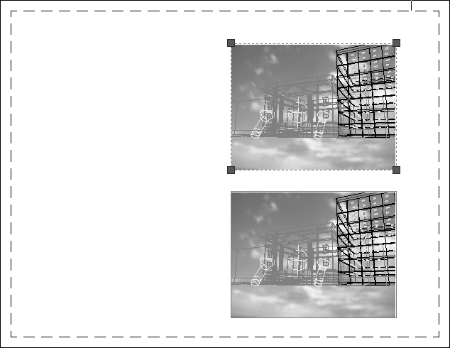
Figure 23-84 The final comparison rendering

You can add viewports to include floor plans and elevations if needed. Another option is to add isometric views with labels that point out drawing features.
You also have control over the quality of the rendered viewport. If you go to the layout view, right-click the Quick View Layout tool in the status bar, and choose Page Setup Manager, the Page Setup Manager dialog box opens. Click the Modify button to open the Page Setup dialog box. You can use the Shaded Viewport Options group to select from a set of viewport-quality settings (see Figure 23-85).
Figure 23-85 Select a quality setting from the Quality drop-down list.
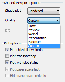
You can choose from Draft, Preview, Normal, Presentation, Maximum, and Custom. These options are described in detail in Chapter 8, “Introducing Printing, Plotting, and Layouts,” so we won’t go into detail here. Just remember that the options are available to help you get the most from your rendered printer output.
Simulating Natural Light
Most of the rendering you’ve done so far relies on fairly simple lighting methods. These methods can give you a decent rendering in a short amount of time, and you’ll probably do 90 percent of your rendering work using these methods. But you may eventually want to see the way your model looks under more realistic lighting conditions.
AutoCAD offers advanced lighting tools that can add impressive realism to your renderings. These tools simulate the way light behaves in the real world by taking into account the effects of light bouncing off nearby surfaces. In the following sections, you’ll get a glimpse of some of the AutoCAD tools that will give your renderings an added level of realism.
Rendering Interior Views
If you’re more interested in rendering interior architectural views, you should know about some of the advanced rendering settings that are available in AutoCAD 2014. Two groups of settings are particularly important to understand when you’re rendering interior views.
Figure 23-86 is a rendering of a simple model using the material techniques described in this chapter. It also includes a sunlight source. As you can see, the rendering is fairly dark and not interesting.
Figure 23-86 An interior rendering using just the sun
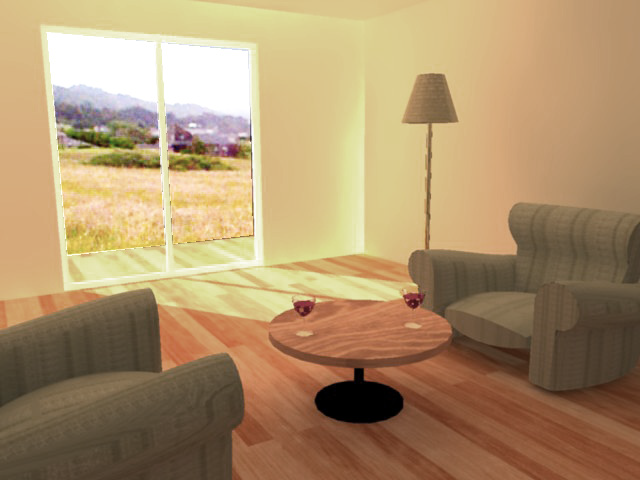
Figure 23-87 is the same model rendered using two advanced rendering features: Global Illumination and Final Gather. Global Illumination simulates the way light bounces off objects in a scene. When you turn on this option, AutoCAD calculates the reflection of light off the various surfaces in the model and applies that reflected light to neighboring objects. For example, the orange hue from the floor is reflected on the walls. The Final Gather feature has the effect of refining the rendering by increasing the amount of detail that Global Illumination produces.
Figure 23-87 The interior rendering shown in Figure 23-86, but with Global Illumination and Final Gather turned on
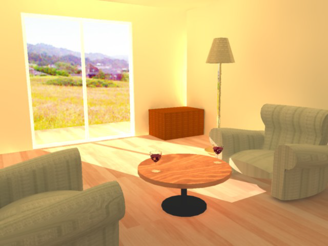
In Figure 23-87, a background image was used to simulate a view out the window. After you’ve rendered your view using Global Illumination, go back to the image you used for a background and adjust its brightness to match the rendering’s brightness.
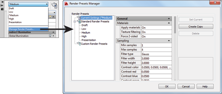
You can turn on and edit these two features using the Advanced Render Settings tool in the title bar of the Render tab’s Render panel. This tool opens the Advanced Render Settings palette, shown in Figure 23-88.
Figure 23-88 The Advanced Render Settings palette
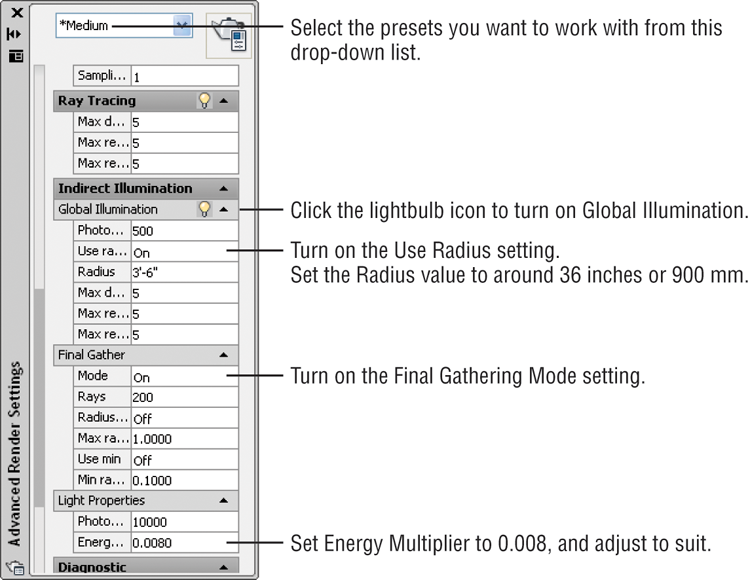
Select the Render preset you want to use from the Select Render Preset drop-down list at the top. You can then turn on the Global Illumination feature by clicking the lightbulb icon in the Global Illumination title bar. To turn on the Final Gather feature, go to the Final Gather Mode option and select On.
Just turning on these features won’t give you great results right away, however. You’ll need to make some careful setting adjustments. First, you must set up your drawing units using the Drawing Units dialog box (choose Drawing Utilities ⇒ Units from the Application menu). Once you’ve done this, you must stick to that unit style. If you choose Architectural, for example, you don’t want to change to Decimal.
After you’ve set your units, turn on the Use Radius setting in the Global Illumination group and then set Radius to 36″. If you’re working in metrics, set Radius to 900 mm or a similar value. If this value is too small, the rendering will appear splotchy.
Next, scroll down to the Light Properties group, and change the Energy Multiplier setting to a value around 0.008.
Once you’ve made these settings, you can render your interior view and see the results. If the direct sunlight is too bright, reduce the sun’s intensity factor by clicking the Sun Properties tool in the title bar of the Render tab’s Sun & Location panel and adjusting the intensity factor in the Sun Properties palette. If the interior appears too dark or too light, adjust the Energy Multiplier value in the Light Properties group of the Advanced Render Settings palette.
You can adjust the sun angle by setting the date and time in the Sun Properties palette. To do quick study renderings, you can turn off Final Gather and increase the Global Lighting Radius setting to 100″ (or 2000 mm). You can also reduce the Global Illumination Photons/Sample setting and the Light Properties Photons/Light setting while making your study rendering. You’ll probably end up making several renderings before you arrive at one that you like.
Although it isn’t perfect, Global Illumination can greatly improve your interior views. You can save time by getting a rendering close to what you want and then using an image-editing program to fine-tune the image.
If you’d like to see how the file used in Figure 23-87 is set up, you can find it as 23-settings.dwg in the projects folder for this chapter. Use the saved view named Scene1 when you render the model.
Using the Sun and Sky Simulation
Just as with the interior view discussed in the preceding section, you can set up AutoCAD to simulate realistic lighting effects in exterior views. Earlier in this chapter, you added a distant light to approximate the light bouncing off the ground. The Sun and Sky Simulation feature in AutoCAD offers a more accurate rendition of reflected light that takes into account the light bouncing off neighboring buildings and surfaces. To see how this feature works, try the following exercise:
If you have a drawing that uses distant lights, you will see a warning message asking if you want to disable distant lights. Leave them enabled by selecting Allow Distant Lights.
By changing the Lightingunits setting, you turn on the Photometric Lighting feature in AutoCAD. The Photometric Lighting feature gives you finer control over the intensity of the lights you add to your model. The Lightingunits system variable can be set to 0 (off), 1 (international units), or 2 (American units). When you are in a perspective view and Lightingunits is set to 1 or 2, you can turn on the Sun and Sky Simulation feature.
This next exercise demonstrates how the Sun and Sky Simulation feature works:
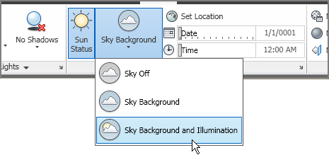
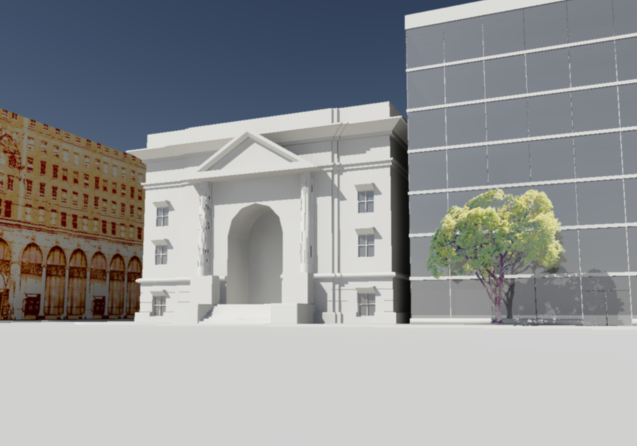
Figure 23-89 The rendering with the Sky Background and Illumination feature turned on
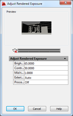
You can further refine your image by adjusting the brightness and contrast. To do this, you use the Adjust Rendered Exposure dialog box:
Figure 23-90 Adjusting exposure in your render
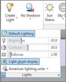
This time, the rendering is brighter and has more contrast. If you prefer, you can also set the Brightness, Contrast, and Midtone settings in the Render tab’s expanded Lights panel (see Figure 23-91).
Figure 23-91 The Lights panel offers Brightness, Contrast, and Midtone settings.
The Sun and Sky Simulation feature causes AutoCAD to take more time to render a view, so you should use it only when you really need the lighting effects it offers.
As mentioned earlier, when the Lightingunits system variable is set to 1 or 2, the Photometric Lighting feature is turned on. Photometric lighting offers additional settings for the sun in the Sun Properties palette. For example, you can set the appearance of the sun disk, the horizon, and the ground color through the Sun Properties palette. You can open the Sun Properties palette by clicking the Sun Properties tool in the title bar of the Sun & Location panel.
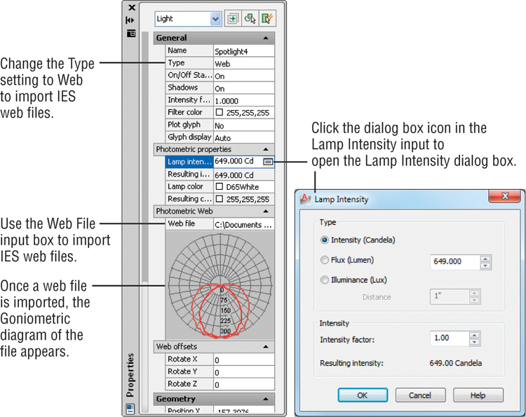
With photometric lighting turned on, you see additional settings in the Properties palette for other types of lights as well. You have finer control over lighting intensity through the Photometric Properties settings area (see Figure 23-92). If you change the Type setting in the General settings area to Web, you can import IES web files that control the way a fixture spreads its light. Once a web file is selected, its goniometric diagram is displayed in the Properties palette, as shown in the figure. A goniometric diagram is a graphic that shows the distribution of light intensity from a light fixture.
Figure 23-92 Photometric lighting offers additional options in the Properties palette for lights.
AutoCAD offers some sample IES web files in the C:ProgramDataAutodeskAutoCAD 2014R19.1enuWebFiles folder. To use these web files, you’ll need to add this location to the Web File Search Path setting in the Files tab of the Options dialog box. See Appendix B, “Installing and Setting Up the Autodesk® AutoCAD® 2014 Software,” for more on the Options dialog box.
This brings us to the end of the chapter. We’ve just scratched the surface of the rendering capabilities in AutoCAD. You’ll want to explore many more features once you get the basics down. To find out more about the Photometric Lighting feature, look up “Photometric and Sky” in the index of the AutoCAD 2014 Help website.