
Chapter 25
Exploring 3D Mesh and Surface Modeling
Autodesk® AutoCAD® software has always offered tools that allow users to construct fairly complex 3D models. With the introduction of the latest solid modeling tools, you can even model some very organic forms. But some types of forms require a type of modeling known as mesh modeling. Mesh modeling enables you to create smooth, curved volumes by manipulating faces that make up an object’s surface.
With mesh modeling, you can quickly create curved shapes that are difficult or even impossible to create by other means. AutoCAD also offers the ability to convert a mesh model into a 3D solid so that you can perform Boolean operations.
In addition, AutoCAD has a set of 3D surface modeling tools that extend its ability to produce and edit curved, organic forms. In this chapter, you’ll get a chance to explore many of the current features of mesh modeling through a series of exercises, and you’ll be introduced to the surface modeling tools. You’ll also learn how you can convert a mesh or 3D surface into a solid. You’ll start by creating a simple shape as an introduction, and then you’ll move on to a more complex form.
In this chapter, you will learn to:
- Create a simple 3D mesh
- Edit faces and edges
- Create mesh surfaces
- Convert meshes to solids
- Understand 3D surfaces
- Edit 3D surfaces
Creating a Simple 3D Mesh
As an introduction to the mesh modeling features in AutoCAD, you’ll draw a simple box and then smooth the box. This first exercise will show you some of the basic mesh modeling tools and what types of control you can exert on a model.
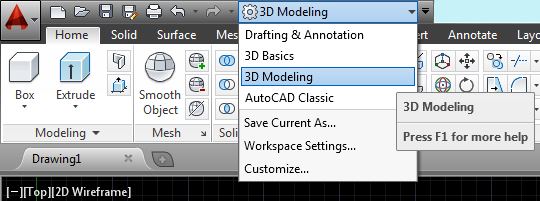
First, you’ll make sure you are in the 3D Modeling workspace and that you have a blank drawing set up for the mesh. Follow these steps:
Figure 25-1 The 3D Modeling workspace
Creating a Mesh Primitive
Meshes are similar to solids in that they start from what is called a primitive. You may recall that 3D solid primitives are predetermined shapes from which you can form more complex shapes. The mesh primitives are very similar to the 3D solid primitives you learned about in Chapter 21, “Creating 3D Drawings,” and Chapter 24, “Editing and Visualizing 3D Solids.” You can see the different mesh primitives that are available by clicking the Mesh flyout in the Primitives panel (see Figure 25-2).
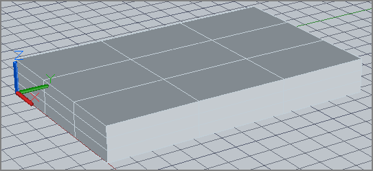
In the next exercise, you’ll use the Mesh Box primitive to start your cushion:
Figure 25-2 The primitives in the Mesh flyout of the Primitives panel
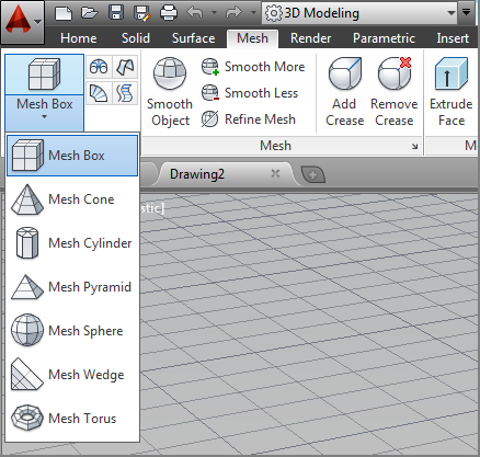
Figure 25-3 The Mesh Box primitive
You’ve just created a mesh box, but you have several other mesh primitives at your disposal. If you click the Mesh flyout on the Primitives panel, you’ll see the cone, cylinder, pyramid, sphere, wedge, and torus primitives. When creating your model, consider which of these primitives will best suit your needs.
Understanding the Parts of a Mesh
Before you go any further, you’ll want to understand the structure of a mesh. Notice that each side is divided into nine panels, or faces, as they are called in AutoCAD. You can edit these faces to change the shape and contour of your mesh. You can control the number of faces of a mesh through an options dialog box that you’ll learn about later.
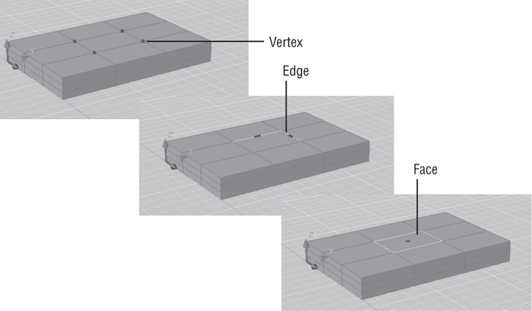
Figure 25-4 shows the names of the different parts of a simple mesh: the vertex, the edge, and the face. These three parts are called subobjects of the mesh, and you can move their position in the mesh to modify a mesh’s shape.
Figure 25-4 The subobjects of a mesh

To help you select different subobjects on a mesh, the Selection panel offers the Filter flyout, which shows the No Filter tool by default. You’ll get to use this flyout in many of the exercises in this chapter.
Smoothing a Mesh
One of the main features of a mesh is its ability to become a smooth, curved object. Right now your cushion has sharp edges, but you can round the corners using the Smooth tools.
Try modifying the mesh to smooth its corners:
Figure 25-5 The mesh after applying the Smooth More tool twice
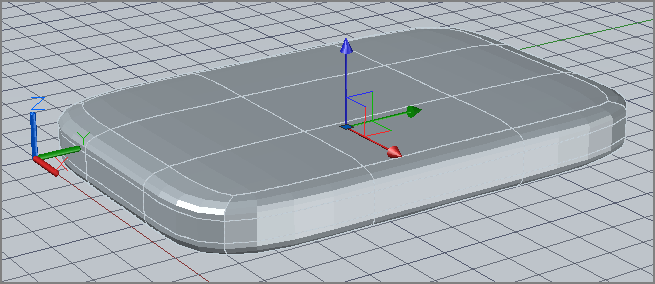
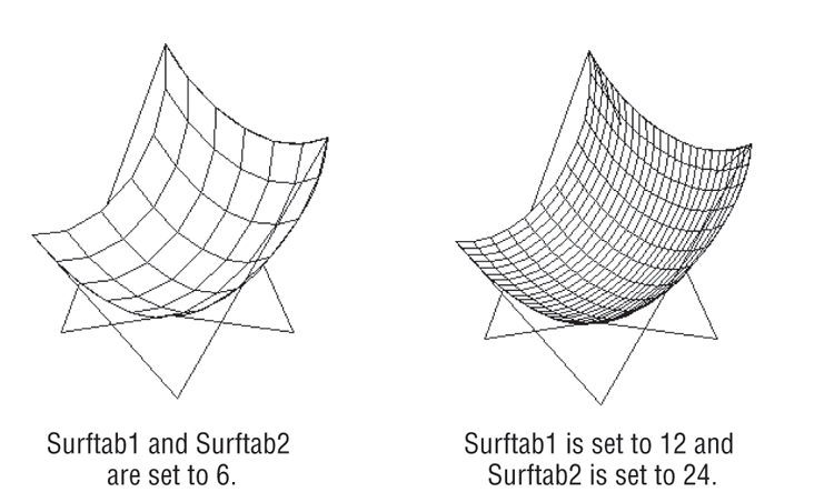
As you can see from this exercise, you can smooth a mesh using the Smooth More tool. The more times you apply it to a mesh, the smoother your mesh becomes. The number of faces of the mesh determines how the Smooth More tool affects the mesh. The fewer the faces, the broader the application of smoothness.
When you apply the Smooth More tool to a mesh, the faces of the mesh become faceted. This simulates the smooth appearance. If you look closely at a mesh that has only one or two levels of smoothing applied, you can see the facets.
Editing Faces and Edges
The shape you created earlier demonstrates one of the main features of meshes. In this section, you’ll create a model of a surfboard to see how you can push and pull the subobjects of a mesh to create a form.
You’ll start with the same form, a box shape, but this time you’ll modify some of the parameters that define the box’s structure. You can control the number of faces that a mesh primitive will have before it is created. The following exercise introduces you to the tools and methods used to edit meshes.
Start by creating a new drawing and setting up the parameters for the mesh:
Figure 25-6 The Mesh Primitive Options dialog box
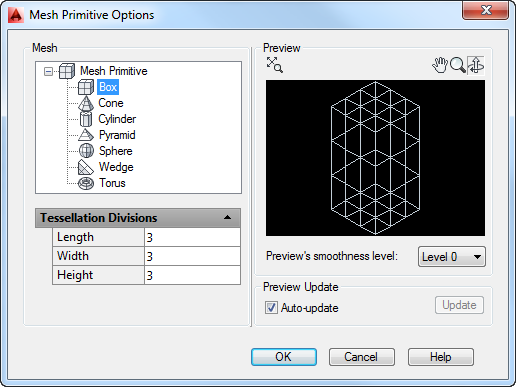
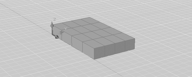
The parameters you change alter the number of faces on mesh primitives that you create, including the box primitive that you will create in the next exercise. You’ll see the results after following the next set of steps:
Figure 25-7 The mesh box
Stretching Faces
You now have the basis for the surfboard, though it might seem like an odd shape for a surfboard. Next you’ll start to form the surfboard by manipulating the faces and edges of the mesh. Start by pulling two sides of the mesh to give it a shape more like a surfboard:
Figure 25-8 Hold down the Ctrl key, and place a crossing selection window as shown here.
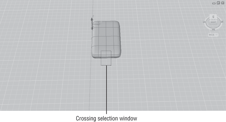
Figure 25-9 Select the Face filter.
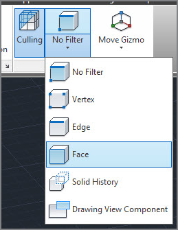
Figure 25-10 Click and drag the gizmo when you see the red axis vector.
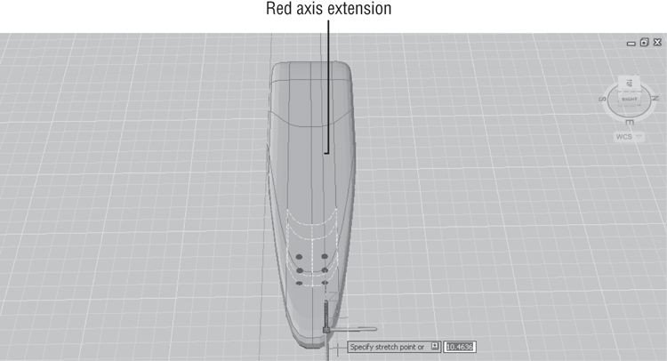
The portion of the mesh you “pull” out will become the front. Next do the same for the back of the surfboard:
Figure 25-11 Place a crossing selection window as shown here. Be sure to press and hold the Ctrl key in order to make the proper selection.
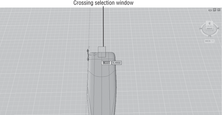
Figure 25-12 Adjust the mesh to look similar to this one.
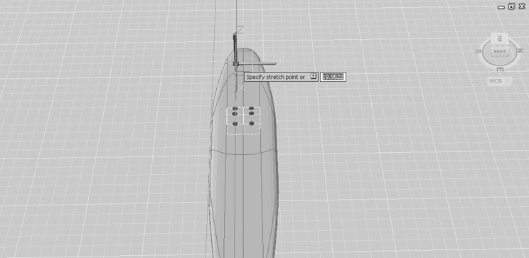
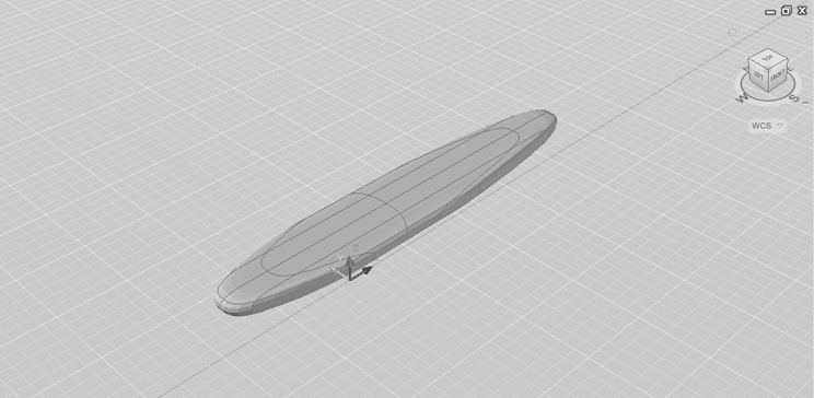
Figure 25-13 The mesh so far
Moving an Edge
The surfboard needs a sharper point at the front. Instead of moving the faces as you’ve already done, you can move an edge to give the front a more pointed shape. The next set of steps will show you how to do this:
Figure 25-14 Click the front-center edge shown here.
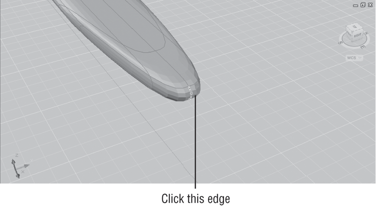
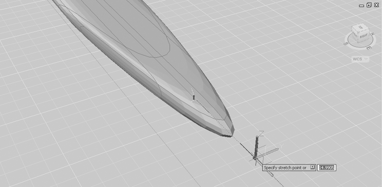
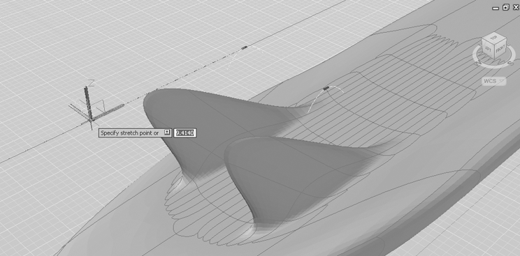
Figure 25-15 Pull the front edge so that the mesh looks similar to this image.
Next, give the front of the mesh a slight curve by adjusting the z-axis of the front edge:
Figure 25-16 Move the front edge downward in the z-axis.
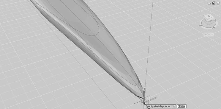
We asked you to adjust the edge downward because you’ll want to have a bottom view of your surfboard. This will enable you to add fins to the board without having to flip the mesh over.
Adding More Faces
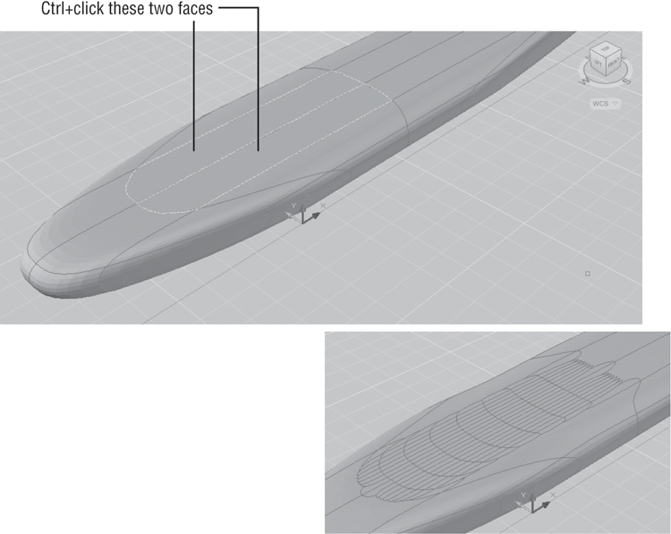
The surfboard is still missing some fins. You could model some fins as separate meshes and then later join them to the surfboard. You can also use the Refine Mesh tool to add more edges and then use those edges as the basis for your fins. The following exercise will show how this is done:
Figure 25-17 Select the faces to refine.
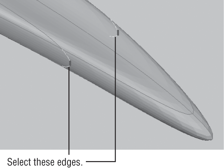
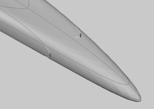
The next step in creating the fins is to edit some of the newly created edges:
Figure 25-18 Select the edges for the fins.
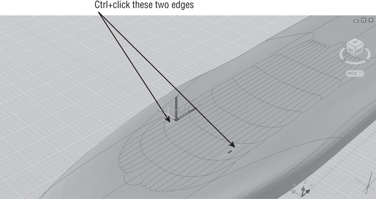
Figure 25-19 Adjust the edges to create the fins.
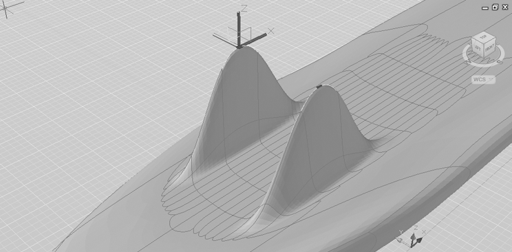
Figure 25-20 Adjust the fins toward the back of the surfboard.
Rotating an Edge
The fins aren’t quite the right shape. They are a bit too broad at the base. The next exercise shows you how to rotate an edge to adjust the shape of the fins further:
Figure 25-21 Click and drag the green circle on the Rotate gizmo.
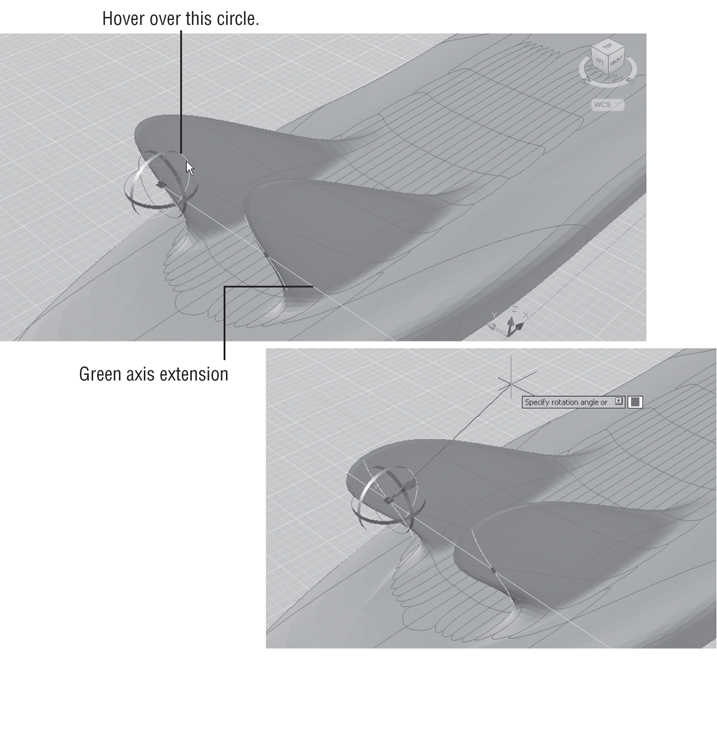
Figure 25-22 Select the Rotate Gizmo tool.
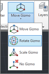
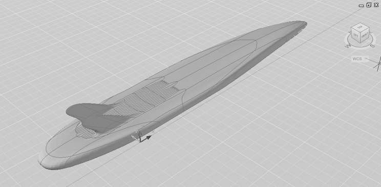
Figure 25-23 The finished surfboard
In this exercise, you switched from the Move gizmo to the Rotate gizmo. You can also use the Scale gizmo to scale a face or edge.
This may not be the most accurate rendition of a surfboard (our apologies if you are a surfer), but the general shape of the surfboard has given you a chance to explore many of the features of the Mesh toolset.
Adding a Crease
You’ll want to know about one more tool that can help you fine-tune your mesh shapes. The Add Crease tool on the Mesh panel does exactly what it says. It can introduce a crease in your otherwise smooth mesh shape. Add Crease does this in two ways: It can flatten a face or remove the smoothing around an edge.
In the following exercises, you’ll use the surfboard one more time to experiment with the Add Crease tool. First you’ll see how you can add a sharp point to the surfboard:
Figure 25-24 Set up your view. Select the front edge of the surfboard.
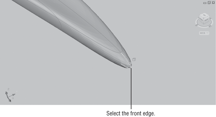
You can see from this exercise that the front edge of the surfboard is now quite sharp since it no longer has any smoothness.
Now try applying the Add Crease tool to a face:
Figure 25-25 Click these faces to flatten them.
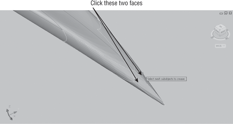
Figure 25-26 The surfboard after applying Add Crease to the side faces on the front
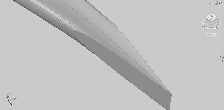
The surfboard is grossly deformed, but you can see how the side faces have now become flat and the edges of the face form a crease. You could use the Add Crease tool to sharpen the edge of the fins. This would also have the effect of making the fins thinner. We didn’t use that example for this exercise because the effects would have been too subtle to see clearly.
Splitting and Extruding a Mesh Face
Before we move on to the next topic, there are two more tools that can be a great aid in editing your meshes. The Split Face tool does just what its name says. It will split a face into two faces. The Extrude Face tool behaves like the Extrude Face tool you have seen for 3D solids. Both of these tools are a bit tricky to use, so they bear a closer look.
To use the Split Face tool, you first select a mesh face, and then select two points, one on each side of the face. The following exercise shows how it works:

Figure 25-27 Selecting the points for the split
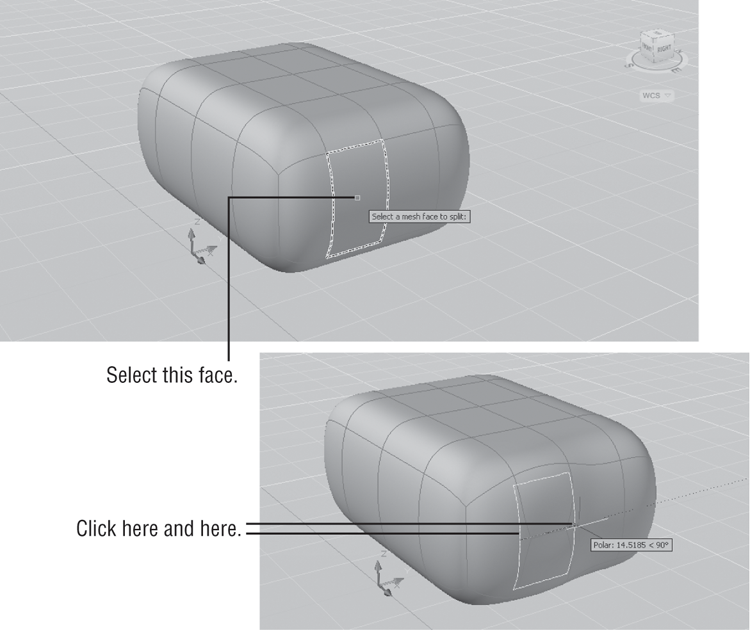
As you can see, Split Face is not a precision tool, but if you don’t like the location of the split, you can move the newly created edge using one of the gizmos.
Next let’s look at the Extrude Face tool. At first, you might think that the Extrude Face tool is redundant since you can use the Move gizmo to move a face in a direction away from the mesh, as you saw in an earlier exercise. Using the Extrude Face tool is different from moving a face because it isolates the movement to the selected face as much as possible. To see how this works, try the following:
Figure 25-28 Select this face.
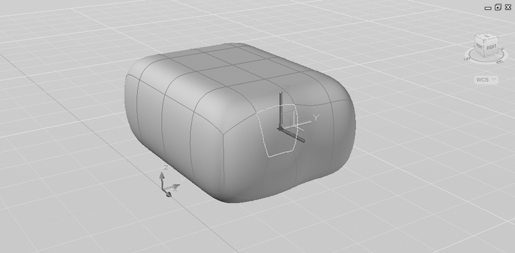
Figure 25-29 A moved face and an extruded face
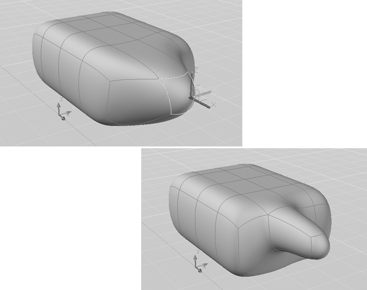
You can see from this example that the Extrude Face tool confines the deformation of the mesh to only the face you select. Note that you can select multiple faces for the extrusion.
Creating Mesh Surfaces
So far, you’ve been working with mesh volumes, but the Primitives panel of the Mesh tab offers four tools that let you create a variety of surface meshes. These are the revolved, edge, ruled, and tabulatedsurfaces. If you’re an old hand at working with 3D in AutoCAD software, then these tools should be familiar. They are the latest incarnation of some of the earliest 3D tools offered by AutoCAD, and they work exactly like the old features they replace. But just like the mesh volumes you’ve been working with, the mesh surfaces can be quickly smoothed and their subobjects can be edited using the gizmos you learned about in this and earlier chapters. The following sections give a little more detail about these tools and how they are used. The figures used in these sections are taken directly from the cue cards for each tool.
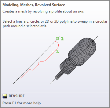
Revolved Surface
To create a revolved surface, you need a profile to revolve and a line that acts as an axis of revolution (see Figure 25-30). The profile can be any object, but a polyline or spline is usually used.
Figure 25-30 The Revolved Surface tool’s cue card
To create a revolved surface, follow these steps:
Edge Surface
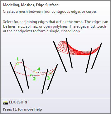
In Chapter 22, “Using Advanced 3D Features,” you learned how to use the Loft tool to draw a butterfly chair that has the shape of a draped fabric seat. Other 3D modeling tools have been introduced into AutoCAD in recent releases that you could use to create the seat. One tool to use in the butterfly chair example is the Edge Surface tool (see Figure 25-31). This tool is a bit trickier to use only because the objects defining the surface must be selected in sequential order. In other words, you can’t randomly select the objects.
Figure 25-31 The Edge Surface cue card
Here’s how it works:
Ruled Surface
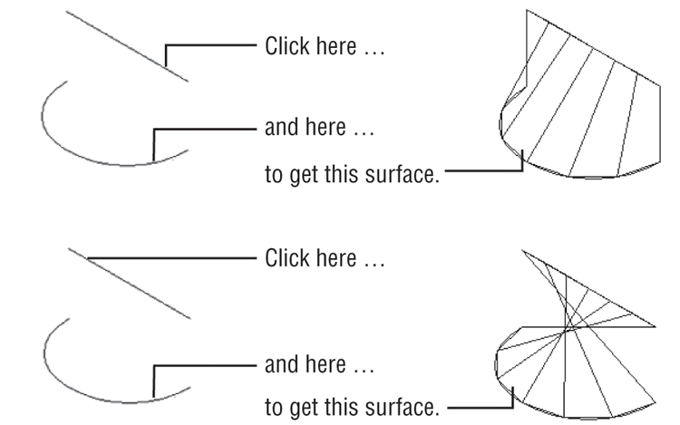
The Ruled Mesh tool creates a surface mesh from two 2D objects such as lines, arcs, polylines, or splines. This is perhaps the simplest mesh tool to use since you have to click only two objects to form a mesh (see Figure 25-32). But like Edge Mesh, it has a tricky side. The location where you click will affect the way the mesh is generated. You’ll want to click the same side of each object unless you want the surface to twist, as shown in Figure 25-33.
Figure 25-32 The Ruled Surface cue card
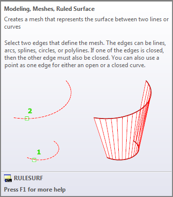
Figure 25-33 Where you click an object affects the outcome.
To create a ruled mesh, follow these steps:
Tabulated Surface
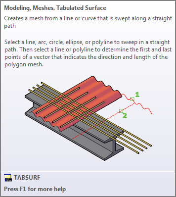
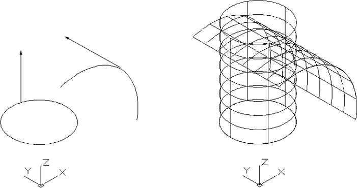
The Tabulated Mesh tool is like an extrude tool for surfaces (see Figure 25-34). Chapter 21 showed you how you can use the Extrude tool to create a 3D solid from a closed polygon. The Extrude tool will also work on open polygons, lines, and arcs, but it will extrude the object in only a perpendicular direction. The Tabulated Surface tool lets you “extrude” an object in a direction you control with a line. The line can point in any direction in space.
Figure 25-34 The Tabulated Surface cue card
Here’s how to use it:
As with the other surface mesh tools, the point at which you select objects will affect the way the object is generated. For the tabulated mesh, the direction of the mesh depends on where you click the line that defines the surface direction.
Converting Meshes to Solids
We mentioned earlier that you can convert a mesh to a solid. In doing so, you can take advantage of the many solid-editing tools available in AutoCAD. The Boolean tools can be especially useful in editing meshes that have been turned into solids.
Conversion is a fairly simple process using the tools in the Convert Mesh panel of the Mesh tab. Just click the Convert To Solid tool, or type Convtosolid↵, and then select the mesh or meshes you want to convert. Press ↵ to complete the process. The Convert To Surface tool (Convtosurface↵) works in much the same way, but it creates a surface object instead of a solid.
When you convert a mesh to a solid, you have the option to apply more or less smoothing to the conversion process. The Smoothed, Optimized flyout in the Convert Mesh panel gives you four options. You can select one of these options before you use the Convert To Solid or Convert To Surface tool to get a different smoothing effect during the conversion. Table 25-1 describes these options and how they affect the conversion of meshes.
Table 25-1: Options on the Convert Mesh panel’s flyout
| Option | Effect on mesh |
| Smoothed, Optimized | The mesh is smoothed and the faces are merged. |
| Smoothed, Not Optimized | The mesh is smoothed but maintains the same number of faces as the original. |
| Faceted, Optimized | The facets are maintained, and the smoothing remains the same but planar faces are merged. |
| Faceted, Not Optimized | The facets are maintained, the smoothing remains the same, and the number of faces also remains the same. |
Understanding 3D Surfaces
So far in this book you’ve worked with 3D solids and meshes. A third type of 3D object called a surface completes the AutoCAD set of 3D modeling tools to make it a complete 3D modeling application in its own right.
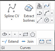
Click the Surface tab, and you’ll see the Surface panels that offer the tools you’ll need to work with surface modeling (see Figure 25-35).
Figure 25-35 The Surface tab and Ribbon panels

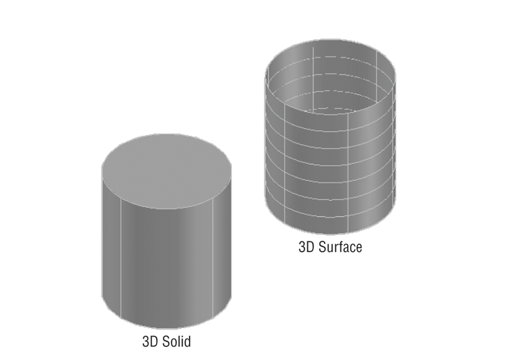
In the Create panel, you see a different set of tools than what was in the Mesh and Solid tabs, but a handful should look familiar. The Loft, Sweep, Extrude, and Revolve tools at the far left of the Create panel are tools you’ve seen in previous chapters. These surface creation tools work in the same way as the tools of the same name in the Solid tab. In fact, they are essentially the same tools. They just use a different command option to create a surface instead of a solid. The big difference is that to create a solid, you need to start with a closed polyline. With the surface version of the Loft, Sweep, Extrude, and Revolve tools, you can start with an open spline, polyline, or other object. And even if you do use a closed object such as a circle or closed polyline, you will still get a 3D surface instead of a solid (see Figure 25-36).
Figure 25-36 A circle extruded using the solid Extrude and the surface Extrude
Two other surface-creation tools that are unique to the Surface tab of the Ribbon are the Network Surface and Planar Surface tools. Here’s a brief description of each:
Figure 25-37 The cue card description of the Network Surface tool
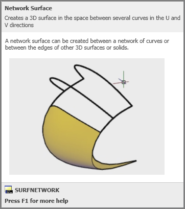
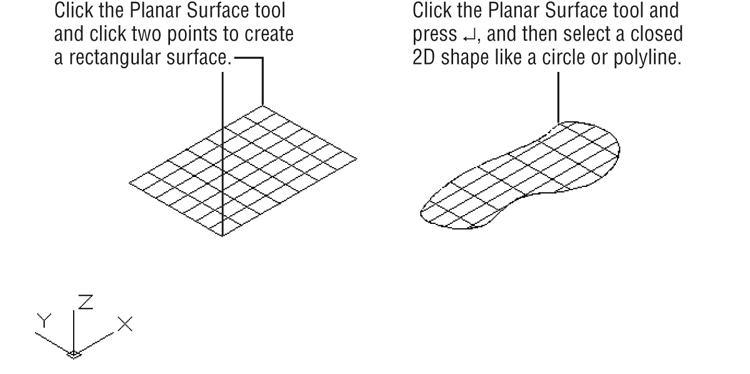
Figure 25-38 Creating a planar surface
Editing Surfaces
Once created, surface objects have a unique set of editing tools that allow you to create fairly detailed models. Some tools, like Surface Fillet and Surface Trim, offer the same function as their 2D drawing counterparts. The following list includes a description of each tool:
Figure 25-39 Using the Surface Fillet and Surface Trim tools
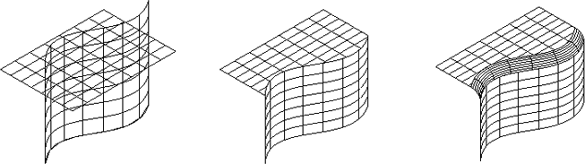
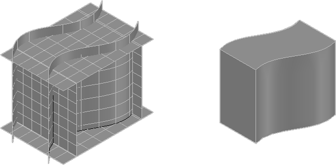
Figure 25-40 The Surface Sculpt tool creates a container-like shape from several surfaces.
The Create panel also offers three other tools that could be considered editing tools. Blend, Patch, and Offset need existing surfaces to do their job, so they may seem a bit like editing tools. Here’s a description of each:
Figure 25-41 The Surface Patch tool can create a flat or rounded patch over an open surface.
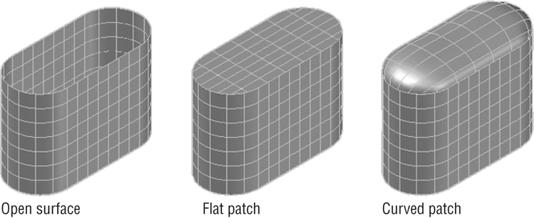
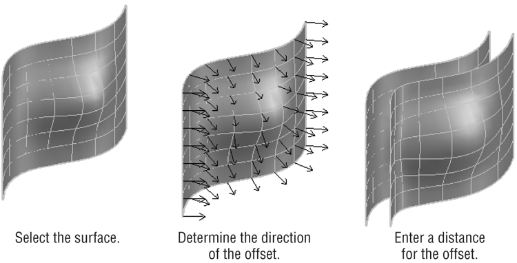
Figure 25-42 Using the Create panel’s Surface Offset tool
Using Extrude, Surface Trim, and Surface Fillet
Now that you have an overview of the basic surface modeling tools, try the following set of exercises to see how they work.
Using the Extrude Tool
Start with the Extrude tool on two basic shapes:
Figure 25-43 Extrude the circle and arc (left image) 5 units to look like the image on the right.
As you can see, the Extrude tool is similar to the Extrude tool in the Solid tab in how it works, but the objects created are surfaces.
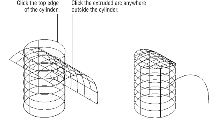
Using the Surface Trim Tool
The Surface Trim tool is similar to the 2D Trim tool except that there is an additional step at the beginning, where you select the object you intend to trim. At first this step seems redundant, but after you use the tool for a while, it begins to make more sense. Also notice that the original arc you used to extrude the arc surface is still there. You’ll use that a little later in this chapter.
Next try out the Surface Trim tool:
Figure 25-44 Trimming the surfaces
Using the Surface Fillet Tool
Now try out the Surface Fillet tool:
Figure 25-45 Using the Surface Fillet tool
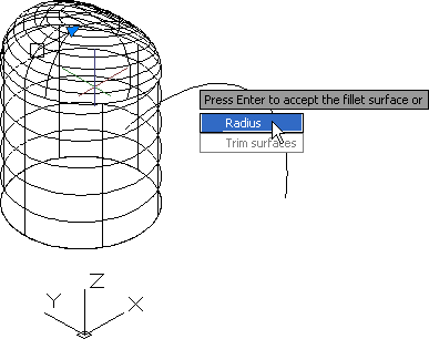
In this case we created a fillet all of the way around the top of the cylinder. While you’re creating surface fillets, you’ll see a preview of what the new surface will look like. You don’t have to stick with that fillet until you fully finish the command; you are free to make changes to the fillet until then.
Using Surface Blend, Patch, and Offset
As mentioned earlier, a few of the tools on the Create panel are a bit like editing tools. Surface Blend, Surface Patch, and Surface Offset create new surfaces that use existing surfaces as their basis. Surface Blend is a bit like the Surface Fillet tool in that it will join two surfaces with an intermediate surface. Surface Offset creates a new surface that is parallel to an existing one and is similar to the 2D offset command. Surface Patch will create a surface that closes an open-ended surface.
To get a better idea of how these three tools work, try the following set of exercises. Start by creating a parallel copy of an existing surface using the Offset tool:
Figure 25-46 Using the Surface Offset tool
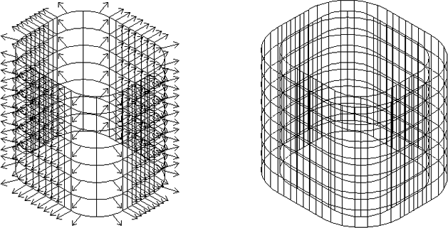
Here you see how the Surface Offset tool differs from the 2D Offset tool that you’ve seen in Chapter 19, “Drawing Curves.” The arrows play an important role in helping you visualize the result of your offset, so instead of picking a direction, you adjust the direction of the arrows.
Using the Surface Blend Tool
Now try the Surface Blend tool:
Figure 25-47 Selecting the edges for the Surface Blend tool
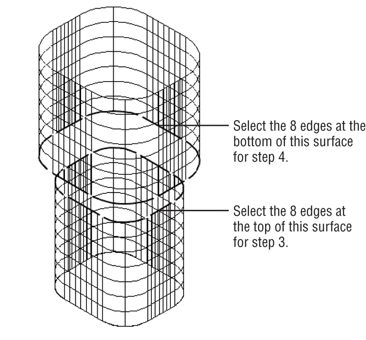
Figure 25-48 Using the grip arrowhead to adjust the blend surface
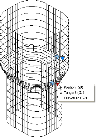
The Surface Blend tool offers a number of options that control the shape of the blend surface. You saw three options available from the grip arrowhead. The options are available even after you have placed the surface. You can click on the surface to expose the grip arrowheads.
In addition, the Surface Blend tool offers two command options: CONtinuity and Bulge Magnitude. Table 25-2 in the next section describes these features and their functions.
Using the Surface Patch Tool
Now let’s take a look at the Surface Patch tool. This tool lets you close the end of a surface with another surface. You can add a flat or curved surface, as you’ll see in the next exercise.
Try adding a patch surface to the top of the upper surface in the Patch1.dwg model:
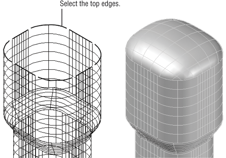
Figure 25-49 Adding the patch surface to the end of the model
You may have noticed that the grip arrowhead options in step 5 were similar to the grip options you saw for the Surface Blend tool. The Surface Patch tool offers an additional command option called CONStrain Geometry. Table 25-2 describes these options.
Table 25-2: The Blend and Patch options
| Feature option | Function |
| Position (G0) | Causes the surface to connect without any blending curvature. |
| Tangent (G1) | Causes the surface to blend with direction. |
| Curvature (G2) | Causes the surface to blend with direction and similar curvature or similar rate of change in the surface direction. |
| Command option | Function |
| CONtinuity | Controls how smoothly the surfaces flow into each other. |
| Bulge Magnitude | Allows you to adjust the amount of bulge or curvature in the blend surface. Values can be between 0 and 1. |
| CONStrain Geometry (Surfpatch command) | Offers additional guide curves to control the patch surface. |
Understanding Associativity
You may have noticed the Surface Associativity icon in the Create panel. This is a feature that is on by default, and its function is similar to the Associative feature of hatches (see Chapter 7, “Mastering Viewing Tools, Hatches, and External References,” for more on hatches). You may recall that when you create a 2D hatch pattern with the hatch associative feature turned on, the hatch’s shape will conform to any changes made to the boundary used to enclose the hatch pattern.
The Associativity feature in surface modeling works in a similar way, only instead of a hatch pattern conforming to changes in a boundary, the surface conforms to changes in the shapes that are used to create them. For example, if you were to make changes to the arc that you used to extrude the arc surface, the arc surface and the trimmed cylinder would also follow the changes.
Using Associativity to Edit a Surface Model
This concept is a bit tricky to explain. Try the following exercise to see how associativity works firsthand:
Figure 25-50 Adjusting the shape of the arc
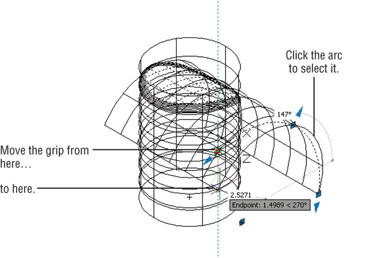
Figure 25-51 Adjusting the fillet radius
Using Arrowhead Grips to Edit a Surface
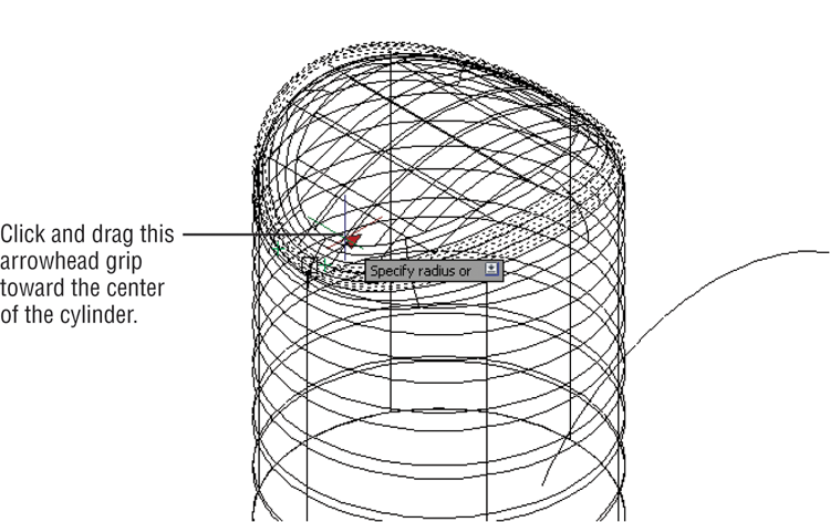
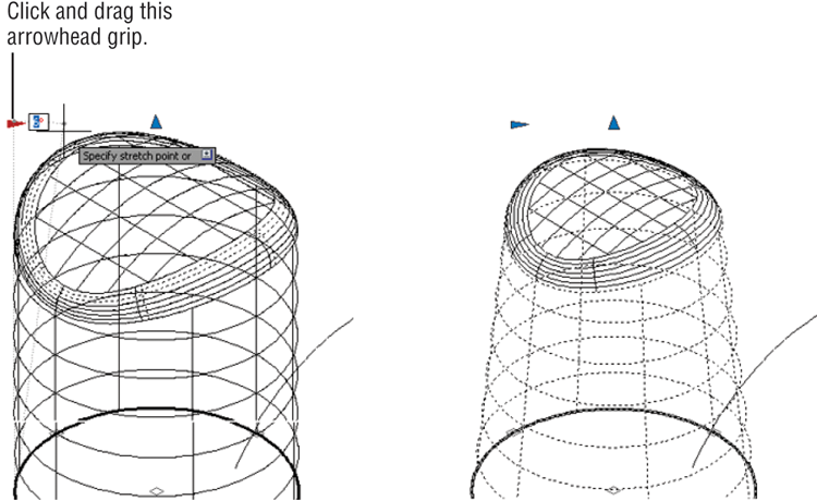
You’ve just seen the Associativity feature in action. You can also change the shape of the circle used to extrude the cylinder to modify the surface model’s diameter. Additional hidden grips are available that allow you to adjust the shape of the surfaces directly. For example, you can modify the taper of the cylinder using an arrowhead grip that you can turn on using the Properties palette, as shown in these steps:
Figure 25-52 Changing the taper of the cylinder
Surface Associativity can be very useful, but in order to take full advantage of this feature, you will want to plan your model construction carefully. In addition, the Associativity feature can limit some editing and creation functions. For example, the Surface Fillet tool may not work on a complex surface model with associativity turned on but will work when the associativity is turned off for the objects involved.
Turning Off or Removing Associativity
You can turn off or remove associativity for an object through the Properties palette. Select the object, and then right-click and select Properties. In the Properties palette, scroll down the palette to the Surface Associativity group (see Figure 25-53). This group offers two options: Maintain associativity and Show associativity. The Maintain associativity option offers Yes, Remove, and None.
Figure 25-53 The Surface Associativity group in the Properties palette
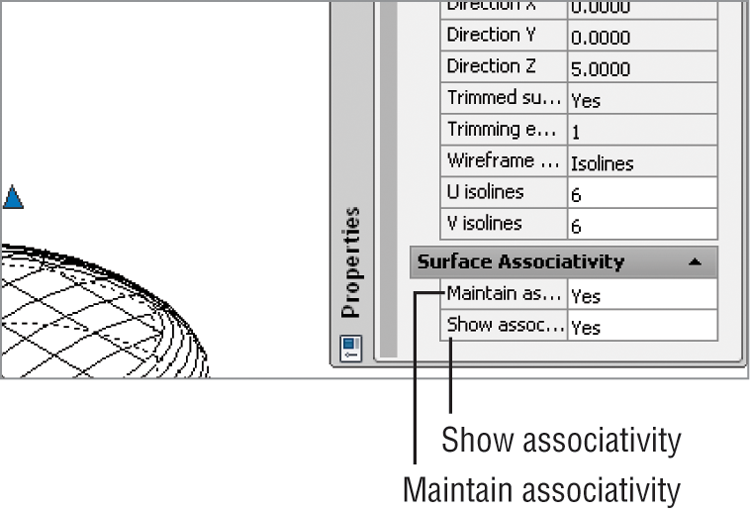
You can select Remove to remove associativity altogether or None to limit the associativity to the set of objects currently associated with the surface model. Once you change this setting, you can’t return to a previous setting except with the Undo command.
Editing with Control Vertices
So far you’ve been creating what are called procedural surfaces, which are surfaces that allow you to take advantage of associativity. AutoCAD also allows you to create NURBS surfaces. You may recall that splines are also NURBS, so you might think of a NURBS surface as a kind of 3D surface spline. Splines allow you to move, add, or subtract control vertices (CVs), and you can control the way the CVs “pull” on the curve of the spline. Likewise, NURBS surfaces allow you to add or remove CVs and adjust the direction and force of the CVs.
There are two ways to create a NURBS surface. You can turn on the NURBS Creation option in the Surface tab’s Create panel and then go about creating your 3D surfaces. Any 3D surface you create with this option turned on will be a NURBS surface. Or you can convert an existing surface to a NURBS surface.
Converting a Surface to a NURBS Surface

You can convert an existing surface to a NURBS surface by using the Convert To NURBS tool on the Surface tab’s Control Vertices panel. This tool also converts 3D solids and meshes. To use it, follow these steps:

If you want to create NURBS objects, be sure to turn on NURBS Creation. It’s easier to create objects as NURBS than to have to go through the extra step of converting them later.
Exposing CVs to Edit a NURBS Surface
You’ve just created a NURBS surface. You can expose the CVs for the surface using the Show CV tool. Try the following to view and edit the CVs:
Figure 25-54 Exposing the CVs
In this exercise, you saw how you can gain access to the CVs of a NURBS surface to make changes to the shape. Right now, the CVs are located only at the top and bottom of the surface, but you can add more CVs to give you more control over the shape of the surface.
Adding CVs to a NURBS Surface
The next exercise shows you how you can add additional CVs through the Rebuild option:
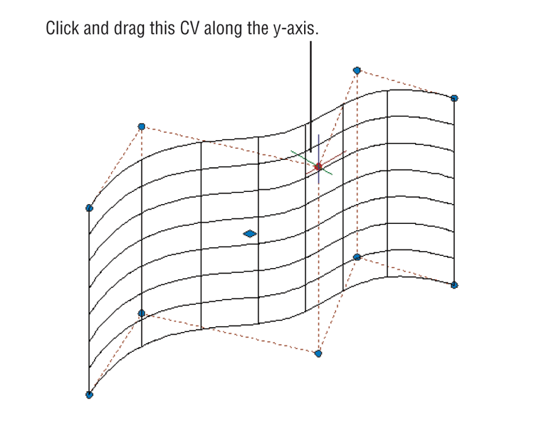
In step 2 you specified the number of CVs you want in the U and V directions. The U direction is along the horizontal curve, and the V direction is along the straight, vertical direction. If you count the CVs in each row or column, you’ll see that they match the values you entered in step 2.
Now if you were to move a CV, the surface is able to deform along the z-axis, whereas it remained a straight line before.
Figure 25-55 The Rebuild Surface dialog box
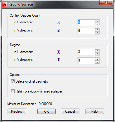
The Rebuild Surface dialog box offers a number of other options you’ll want to know about. Table 25-3 gives you a rundown.
Table 25-3: The Rebuild Surface dialog box
| Section/option | Effect |
| Control Vertices Count | |
| In U Direction | Sets the number of CVs in the U direction |
| In V Direction | Sets the number of CVs in the V direction |
| Degree | |
| In U Direction | Sets the number of CVs available per span in the U direction |
| In V Direction | Sets the number of CVs available per span in the V direction |
| Options | |
| Delete Original Geometry | Determines whether the original geometry is retained |
| Retrim Previously Trimmed Surfaces | Determines whether trimmed surfaces are retained from the original surface |
| Maximum Deviation | Displays the maximum deviation between the original and rebuilt surface |
Two other tools just below the Surface Rebuild tool allow you to either add or remove a set of CVs. The Surface CV – Add tool lets you place a row of CVs. The Surface CV – Remove tool will remove a row of CVs. Both options allow you to toggle between the U and V directions for the row addition or removal by typing D↵.
The Surface CV Add and Remove tools can be useful when you want to fine-tune the curvature of a surface. Where you want a “tighter” curve, you can add more CVs to an area of the surface. You can then move the CVs in the selected area to increase the curvature. To smooth out the curvature of an area, remove the CVs.
Editing with the CV Edit Bar
You’ve seen how a NURBS surface can be set up to add additional CVs, which in turn allow you to adjust the shape of the surface. But the CVs by themselves allow you to adjust their pull on the surface only by moving them closer or farther away from the surface.
The CV Edit bar gives you more control over the behavior of individual CVs. With the CV Edit bar, you can change the strength and direction of the “pull” exerted by a CV.
Try the following exercise to see how the CV Edit bar works:

Figure 25-56 The CV Edit bar’s U and V directions are shown by two red lines.
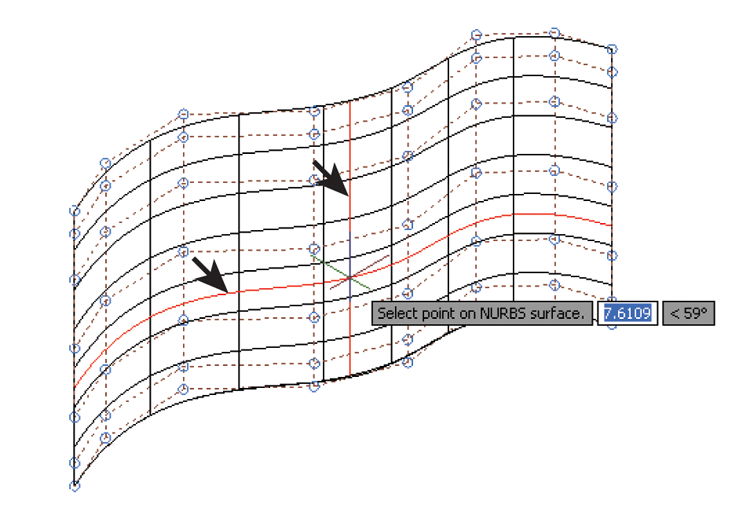
Figure 25-57 The magnitude handle and expansion grip
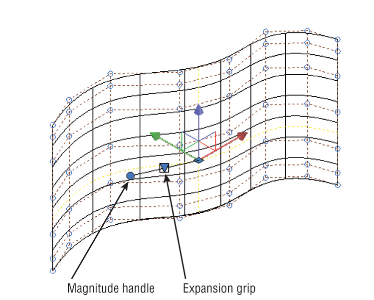
The Move gizmo gives you a bit more control over the location of the CV since it allows you to isolate movement in the X, Y, or Z direction. The expansion grip lets you change the tangency of the CV, whereas the magnitude grip lets you control the strength of the CV.
Try the following steps to see how these two features work:
As you can see from this exercise, the CV Edit bar gives you much more control over a CV than you would have otherwise. You also saw the context menu for the CV Edit bar in step 6 (see Figure 25-58). The context menu allows you to change the direction of the magnitude grip, but it also lets you switch the position of the Move gizmo and the expansion grip with the Move Point Location and Move Tangent Direction options. The Relocate option enables you to move to a different CV location. Table 25-4 includes descriptions of these options.
Figure 25-58 The CV Edit bar’s context menu
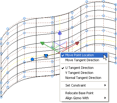
Table 25-4: The CV Edit bar’s right-click options
| Option | Purpose |
| Move Point Location | Places the Move gizmo at the CV location |
| Move Tangent Direction | Places the Move gizmo at the expansion grip location to allow adjustment to the tangent direction of the CV |
| U Tangent Direction | Aligns the magnitude grip to the surface’s U direction |
| V Tangent Direction | Aligns the magnitude grip to the surface’s V direction |
| Normal Tangent Direction | Aligns the magnitude grip to a direction that is normal (perpendicular) to the surface |
| Set Constraint | Constrains changes to the tangency in a specific direction such as X, Y, or Z or in a plane defined by a pair of axes |
| Relocate Base Point | Moves the CV Edit bar to a different location on the surface |
| Align Gizmo With | Aligns the gizmo with the world or current UCS or with a face on the surface |
Making Holes in a Surface with the Project Geometry Panel
Eventually, you’ll need to place an opening in a surface, so AutoCAD offers the Project Geometry panel. This panel contains several tools that allow you to project a closed 2D object’s shape onto a 3D surface. For example, if you want to place a circular hole in the surface you edited in the previous exercise, you would draw a circle parallel to that surface and then use the Surface Projection UCS tool.
Try the following exercise to see how the Project Geometry feature works:
In this exercise, you aligned the UCS to the circle. The Surface Projection UCS tool you used in step 6 projected the circle in the z-axis of this new UCS that is aligned with the circle.
Figure 25-59 The circle projected onto the surface
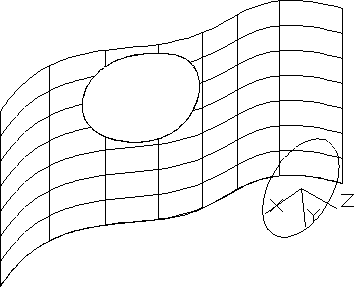
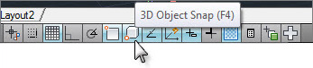
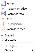
The other two Project Geometry tools use different criteria to project geometry. The Surface Projection View projects geometry along the line of sight. If you had used this tool in the previous exercise, the projected circle and opening would appear directly behind the circle in your current view. The Surface Projection Vector projects geometry along a vector that you indicate with two points. You can use the 3D object snaps to select points on the geometry and the surface.
Visualizing Curvature: Understanding the Analysis Panel
In addition to the surface editing tools, AutoCAD offers several surface analysis options. These options offer some visual aids to help you see the curvature of your surface models more clearly. They can be found in the Analysis panel of the Surface tab and are called Analysis Zebra, Analysis Curvature, and Analysis Draft.
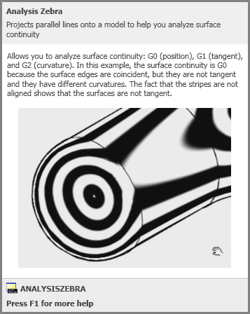
Analysis Zebra displays stripes that allow you better to visualize how the curvatures of surfaces blend (see Figure 25-60). The smoother the stripes, the better the transition between surfaces.
Figure 25-60 The cue card description for Analysis Zebra
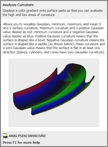
Analysis Curvature displays colors to indicate the direction and amount of curvature in a surface (see Figure 25-61). As the cue card describes, a negative curvature is a saddle shape and displays a blue color. A positive curvature, or bowl shape, displays in red.
Figure 25-61 The cue card description for Analysis Curvature
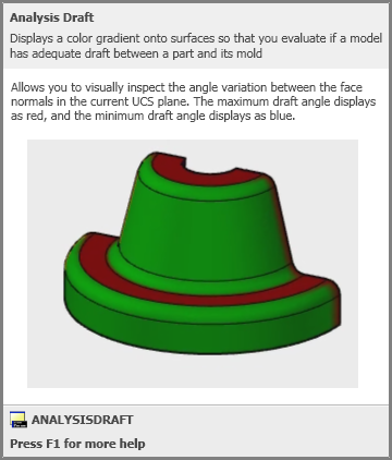
Analysis Draft displays colors to help you determine draft angles (see Figure 25-62). Draft angles are often used in the design of objects that are to be cast from a mold, and they are important in allowing the cast object to be removed easily from the mold.
Figure 25-62 The cue card description for Analysis Draft
The Analysis Options tool opens the Analysis Options dialog box, which enables you to control the way the different analysis tools are displayed. Note that graphics hardware acceleration must be turned on before you can use these tools. You must also use a visual style other than Wireframe.
To turn on graphics hardware acceleration, right-click the Hardware Acceleration tool in the right portion of the status bar and select Hardware Acceleration.