Appendix B
Installing and Setting Up AutoCAD
This appendix gives you information about installing Autodesk® AutoCAD® 2014 software on your system and describes the system parameters you should set to configure AutoCAD to meet the needs of your operating environment. Throughout this appendix, the system variable associated with a setting, when available, is included at the end of an option description, enclosed in brackets. System variables are settings that enable you to control the behavior of AutoCAD when you’re using commands and features. You’ll find a detailed description of the AutoCAD system variables on the AutoCAD 2014 Help website.
Before Installing AutoCAD
Before you begin the installation process, be sure you have at least 6 GB of free disk space. You should also have at least an additional 100 MB of free disk space for AutoCAD temporary files and swap files, plus another 20 MB for the tutorial files you’ll create. AutoCAD will work with Microsoft Windows 8, 7, or Windows XP (Home or Professional) with Service Pack 3. AutoCAD also works with Internet Explorer 7.0 or later.
For 2D work, you’ll also need a dual-core processor with at least 2 GB of RAM and a video card that supports at least 1024×768 resolution and True Color.
For serious 3D work, Autodesk recommends 4 GB of RAM, 6 GB of free disk space (not including the AutoCAD installation), and a 128 MB or greater Direct3D-capable workstation-class graphics card. Autodesk has a list of certified graphics cards for 3D modeling. This list is always being updated, so check the Autodesk website for the latest information.
Single-user systems have a 30-day grace period, so you can install and use AutoCAD without entering your authorization code right away. You can authorize your installation over the Internet at any time within the 30-day grace period as indicated when you first start AutoCAD. The trial software that comes with this book can’t be authorized, so be sure you have a good block of free time to study AutoCAD before you install it.
Proceeding with the Installation
AutoCAD 2014 installs like most other Windows programs, but you should know a few things before you start.
Installing AutoCAD is straightforward. AutoCAD uses an installation wizard like most other Windows programs. Here are some guidelines to follow during the installation process:
- Before you start, make sure you have enough disk space, and also make sure no other programs are running. You’ll need your AutoCAD serial number and product key, which are usually on the package label. If you’re installing the trial version from the Autodesk website, select the “I want to try this product for 30 days” option on the Product Information page of the installation wizard.
- Typically, the AutoCAD installation program starts automatically when you insert the AutoCAD 2014 DVD into your computer. In the event that it doesn’t, do the following:
1. In Windows, choose Start ⇒ Run to open the Run dialog box.
2. In the Open box, enter D:setup. Enter the letter of your DVD drive in place of the D in this example. Click OK when you’re ready. The AutoCAD 2014 Master Setup dialog box opens.
3. After the installation starts, follow the directions in the installation wizard.
4. You’re asked to select the location for your AutoCAD files. The exercises in this book assume that you have AutoCAD on drive C and in a folder called Program FilesAutodeskAutoCAD 2014—these are the defaults during the installation.
5. You’re given the choice of including the Autodesk® Design Review 2014 program and the Autodesk® Inventor® Fusion 2014 program. Click the check box to install the option you desire.
6. The Express tools, management utilities, and sample files are included by default. Although it’s possible to deselect them, go ahead and install them. You might also want to expand the Custom options list and select Visual LISP tutorials and samples for installation.
7. If you don’t have enough disk space, the installation wizard lets you know exactly how much room you need on each drive involved in the installation. You can take steps to make more room by using Windows Explorer or the Windows Disk Cleanup utility. If you do this, make sure you close those programs when you’ve finished making room and before you return to the AutoCAD setup.
8. After the installation is complete, click the Finish button to close the installation dialog box.
If you have an earlier release of AutoCAD installed on your PC, you will see the Migrate Custom Settings dialog box when you first start up AutoCAD 2014. This dialog box enables you to selectively import custom settings from your prior AutoCAD release. If you do not want to import settings, you can click the Cancel button on the dialog box.
Configuring AutoCAD
In the following sections, you’ll learn how to configure AutoCAD to work the way you want it to function. You can configure AutoCAD at any time during an AutoCAD session by using the Options dialog box.
The exercises in this book assume that you’re using the default Options settings. As you become more familiar with the workings of AutoCAD, you may want to adjust the way AutoCAD works by using the Options dialog box. You can also set many of the options in the Options dialog box through system variables.
Choose Options from the Application menu, or type options↵ at the Command prompt to open the Options dialog box, which has the tabs and settings described in the following sections.
Many of the options in the Options dialog box show an AutoCAD file icon. This icon indicates that the option’s setting is saved with individual files instead of being saved as part of the default AutoCAD settings. Other options, such as the User Profiles and command alias settings, can be exported or imported using the Migrate Custom Settings feature. This feature can be found in the Windows Start menu under All Programs ⇒ Autodesk ⇒ AutoCAD 2014 ⇒ Migrate Custom Settings.
The Files Tab
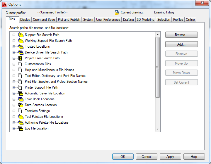
You use the options on the Files tab (see Figure B-1) to tell AutoCAD where to place or find the files it needs to operate. It uses a hierarchical list, similar to the one presented by Windows Explorer. You first see the general topics in the Search Paths, File Names, And File Locations list box. You can expand any item in the list by clicking its plus sign.
The following are descriptions of each item in the list box. Chances are that you won’t have to use most of them, but you may change others occasionally.
When available, the related system variable is shown in brackets at the end of the description.
Support File Search Path AutoCAD relies on external files for many of its functions. Menus, text fonts, linetypes, and hatch patterns are a few examples of features that rely on external files. The Support File Search Path item tells AutoCAD where to look for these files. You can add folder paths to this listing by selecting it, clicking the Add button, and entering a new path, or you can select it and use the Browse button. It’s probably not a good idea to delete any of the existing items under this heading unless you really know what you’re doing.
If you’re familiar with using environment variables, you can include them in the search paths.
Working Support File Search Path The Working Support File Search Path item contains a read-only list of the support file search paths for the current session, together with any special settings that may be included with command switches and environment settings.
Trusted Locations Data security has become an increasingly important feature for Autodesk software. The Trusted Locations option lets you set a location on your system where you keep files that contain trusted executable code. See the Security group under the System tab for related information.
Device Driver File Search Path The Device Driver File Search Path item locates the device drivers for AutoCAD. Device drivers are applications that enable AutoCAD to communicate directly with printers, plotters, and input devices. In most cases, you don’t have to do anything with this setting.
Project Files Search Path Eventually, a consultant or other AutoCAD user will provide you with files that rely on Xrefs or raster images. Often, such files expect the Xref or raster image to be in a particular folder. When they are moved to another location with a different folder system, Xref-dependent files won’t be able to find their Xrefs. The Project Files Search Path item enables you to specify a folder where Xrefs or other dependent files are stored. If AutoCAD is unable to find an Xref or other file, it will look in the folder you specify in this listing.
To specify this folder, highlight Project Files Search Path and then click the Add button. AutoCAD suggests Project1 as the folder name. You can change the name if you prefer. Click the plus sign next to Project1, and then click Browse to select a location for your project file search path. The project file search path is stored in a system variable called Projectname [Projectname].
Customization Files If you’re customizing AutoCAD with your own menu files and icons, you can use this setting to locate your files. This option makes it convenient to keep your customization files in a place that is separate from the built-in AutoCAD files. You can specify a location for the main customization files like your CUI menu files, enterprise customization files for files you want to share, and your custom icons.
Help And Miscellaneous File Names This item lets you set the location of a variety of support files, including menu, help, automatic save, log, and configuration files. If you have a network installation, you can also set the License Manager location on your network.
Text Editor, Dictionary, And Font File Names Use this item to set the location of the text editor [Mtexted], custom and main dictionaries [Dctmain, Dctust], and the alternate font and font-mapping files [Fontalt]. Chapter 10, “Adding Text to Drawings,” describes these tools in more detail.
Print File, Spooler, And Prolog Section Names You can specify a print filename other than the default that is supplied by AutoCAD whenever you plot to a file. The Spooler option lets you specify an application intended to read and plot a plot file. The Prolog option is intended for PostScript export. It lets you specify the Prolog section from the acad.psf file that you want AutoCAD to include with exported Encapsulated PostScript (EPS) files [Psprolog].
Printer Support File Path Several support files are associated with the AutoCAD printing and plotting system. This item enables you to indicate where you want AutoCAD to look for these files.
Automatic Save File Location You can indicate the location for the Automatic Save file in AutoCAD by using this item [Savefilepath].
Color Book Locations This item lets you specify the locations for the PANTONE color books. This is an optional installation item, so if the PANTONE color books aren’t installed, you can install them through your AutoCAD 2014 Installation DVD.
Data Sources Location This item lets you specify the location for Open Database Connectivity (ODBC) data-link files for linking AutoCAD drawings to database files.
Template Settings When you select the Use A Template option in the Create New Drawing dialog box, AutoCAD looks at this setting for the location of template files. You can modify this setting, but chances are you won’t need to do so.
Tool Palettes File Locations This item lets you specify a location for the resource files for your custom tool palettes. When you create custom palettes, AutoCAD stores its data regarding those palettes in this location.
Authoring Palette File Locations If you’re creating custom dynamic blocks, you can designate a folder location where you keep your custom block settings and files.
Log File Location With this item, you can indicate where log files are to be placed [Logfilepath].
Action Recorder Settings The Action Recorder saves action macros as files on your computer. You can specify the location of those saved macros in this option.
Plot And Publish Log File Location With this item, you can indicate where plot and publish log files are to be placed [Logfilepath].
Temporary Drawing File Location AutoCAD creates temporary files to store portions of your drawings as you work on them. You usually don’t have to think about these temporary files unless they start crowding your hard disk or unless you’re working on a particularly large file on a system with little memory. This item lets you set the location for temporary files. The default location is the C:UsersUser Nameappdatalocal emp folder (User Name is your login name). If you have a hard disk that has lots of room and is very fast, you may want to change this setting to a location on that drive to improve performance [Tempprefix, read-only].
Temporary External Reference File Location If you’re on a network and you foresee a situation in which another user will want to open an Xref of a file on which you’re working, you can set the Demand Load Xrefs setting in the Open And Save tab to Enabled With Copy. This causes AutoCAD to make and use a copy of any Xref that is currently loaded. This way, others can open the original file. The Temporary External Reference File Location item lets you specify the folder where AutoCAD stores this copy of an Xref [Xloadpath].
Texture Maps Search Path This item specifies the location for AutoCAD Render texture maps. In most cases, you won’t have to change this setting. You can, however, add a folder name to this item for your own texture maps as you acquire or create them.
Web File Search Path Although you may think this is for Internet files, it’s really for photometric web files that are used to control the way lights behave in 3D models. These files have an .ies filename extension. See Chapter 23, “Rendering 3D Drawings,” for more about using these files.
i-drop Associated File Location This is where you specify the location of files imported to your computer through the i-drop function in AutoCAD. By default, no location is specified, so the i-drop imported DWG file is placed in the same folder location as the current drawing.
DGN Mapping Setup Locations You can specify the location for the DGNsetup.ini file, which is a file used for DGN commands. These commands enable you to import or export DGN files. They also enable you to control the translation of layers, linetypes, lineweights, and color between the AutoCAD DWG file format and the DGN file format.
While in AutoCAD, you may want to quickly find the location of a resource file, such as a log file or the Automatic Save file. You can do so by using the system variable associated with the resource. For example, to find the location of the log file path quickly, enter logfilepath↵ at the Command prompt. For the Automatic Save file, enter savefilepath↵. Autodesk® AutoCAD LT® users can employ the Modemacro command as in Modemacro↵$(getvar,logfilepath)↵ or Modemacro↵$(getvar,savefilepath)↵. See Chapter 26, “Customizing Toolbars, Menus, Linetypes, and Hatch Patterns,” for more on Modemacro.
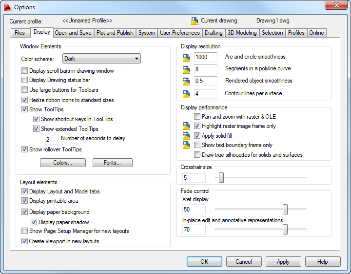
The Display Tab
The settings on this tab (see Figure B-2) let you control the appearance of AutoCAD. You can make AutoCAD look completely different with these settings if you choose. Scroll bars, fonts, and colors are all up for grabs.
The Window Elements Group
These options control the general settings for AutoCAD windows:
Color Scheme Lets you select between a dark or light color scheme for the AutoCAD interface, including toolbars, Ribbon panels, and dialog boxes.
Display Scroll Bars In Drawing Window Lets you turn the scroll bars on and off. If you have a small monitor with low resolution, you may want to turn off the scroll bars for a larger drawing area.
Display Drawing Status Bar When turned on, displays the Annotation Scale settings at the bottom of the drawing area instead of at the bottom of the AutoCAD window.
Use Large Buttons For Toolbars Controls whether large icon buttons are used in toolbars.
Resize Ribbon Icons To Standard Sizes When Ribbon icons do not match the standard sizes, they can be scaled to match the small (16×16) or large (32×32) default pixel size.
Show ToolTips Controls whether tool tips are shown when you hover the mouse over tools [Tooltips].
Show Shortcut Keys In ToolTips Controls whether shortcut keys are displayed in tool tips.
Show Extended ToolTips Controls whether extended tool tips are displayed.
Show Rollover ToolTips Controls whether rollover tool tips are displayed [Rollovertips].
Colors Opens a dialog box that lets you set the color for the various components of the AutoCAD window. This is where you can change the background color of the drawing area if you find that black doesn’t work for you.
Fonts Opens a dialog box that lets you set the fonts of the AutoCAD window. You can select from the standard set of Windows fonts available in your system.
The Display Resolution Group
These options control the way objects are displayed in AutoCAD. You can choose between display accuracy and speed:
Arc And Circle Smoothness Controls the appearance of arcs and circles, particularly when you zoom in on them. In some instances, arcs and circles appear to be octagons even though they plot as smooth arcs and circles. If you want arcs and circles to appear smoother, you can increase this setting. An increase also increases memory use [Viewres].
Segments In A Polyline Curve Controls the smoothness of polyline curves. Increase the value to make curved polylines appear smoother and less segmented. Decrease the value for improved display performance [Splinesegs].
Rendered Object Smoothness Controls the smoothness of curved solids when they’re rendered or shaded. Values can range from 0.01 to 10 [Facetres].
Contour Lines Per Surface Lets you set the number of contour lines used to represent solid, curved surfaces. Values can range from 0 to 2047 [Isolines].
The Layout Elements Group
These options control the display of elements in the Paper Space Layout tabs. See Chapter 8, “Introducing Printing, Plotting, and Layouts,” and Chapter 16, “Laying Out Your Printer Output,” for more information. Most of these options are self-explanatory. The Show Page Setup Manager For New Layouts option opens the Page Setup Manager dialog box whenever a layout is first opened. The Create Viewport In New Layouts option automatically creates a viewport in a layout when it’s first opened.
The Display Performance Group
You can adjust a variety of display-related settings from this group:
Pan And Zoom With Raster & OLE Controls the way raster images react to real-time pans and zooms. If this option is selected, raster images move with the cursor. Turn off this option for better performance [Rtdisplay].
Highlight Raster Image Frame Only Determines how raster images appear when selected. Turn on this option for better performance [Imagehlt].
Apply Solid Fill Controls the display of filled objects such as wide polylines and areas filled with the solid hatch pattern. This option is also controlled by the Fillmode system variable. Turn off this option for better performance [Fillmode].
Show Text Boundary Frame Only Controls the way text is displayed. Turn on this option to display text as rectangular boundaries [Qtextmode].
Draw True Silhouettes For Solids And Surfaces Controls whether surface meshes for solid models are displayed. Turn off this option for better performance [Dispsilh].
The Crosshair Size Group
This slider controls the size of the crosshair cursor. You can set this to 100 percent to simulate the full-screen crosshair cursor of earlier versions of AutoCAD [Cursorsize].
The Fade Control Group
These two sliders control the fade effect on external references. The Xref Display option sets the overall fade effect [Xdwgfadectl]. The In-Place Edit And Annotative Representations option controls the display of nonselected objects during in-place reference editing. See Chapter 7, “Mastering Viewing Tools, Hatches, and External References,” for more information on in-place reference editing [Xfadectl].
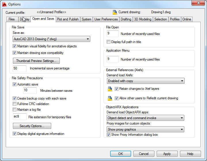
The Open And Save Tab
The Open And Save tab (see Figure B-3) offers general file-related options such as the frequency of the automatic save and the default file version for the Save and Save As options.
The File Save Group
You can control how AutoCAD saves files by using the options in this group:
Save As Lets you set the default file type for the Save and the Save As Application menu options. If you’re working in an environment that requires Release 14 files as the standard file type, for example, you can use this option to select Release 14 as the default file type. You can also set up AutoCAD to save DXF files by default.
Maintain Visual Fidelity For Annotative Objects Ensures that annotative scale is preserved in layouts when you save drawings to earlier versions of AutoCAD. If you work primarily in Model Space, leave this setting off [Savefidelity].
Maintain Drawing Size Compatibility AutoCAD 2014 has no restrictions on object size. This option ensures that restrictions are applied in case you want to save your file to an earlier version [Largeobjectsupport].
Thumbnail Preview Settings Lets you determine whether a preview image is saved with a drawing. Preview images are used in the AutoCAD file dialog box and in DesignCenter™ to let you preview a file before opening it [Rasterpreview]. You can also control the display of the sheet set preview [Updatethumbnail].
Incremental Save Percentage Controls the degree to which the Incremental Save feature is applied when a file is saved. An incremental save improves the time required to save a file to disk, but it also makes the file size larger. If you have limited disk space, you can set this value to 25. A value of 0 turns off Incremental Save altogether but reduces AutoCAD performance [Isavepercent].
The File Safety Precautions Group
These options control the automatic backup features in AutoCAD:
Automatic Save Offers control over the Automatic Save features. You can turn it on or off by using the check box or set the frequency at which files are saved by using the Minutes Between Saves box. You can set the location for the Automatic Save files by using the Automatic Save File Location item in the Files tab of the Options dialog box. You can also set the frequency of automatic saves through the Savetime system variable [Savefilepath, Savefile].
Create Backup Copy With Each Save Lets you determine whether a BAK file is saved along with every save you perform. You can turn off this option to conserve disk space [Isavebak, Tempprefix].
Full-Time CRC Validation Controls the cyclic redundancy check feature, which checks for file errors whenever AutoCAD reads a file. This feature is helpful in troubleshooting hardware problems in your system.
Maintain A Log File Lets you record the data in the AutoCAD Text Window. See Chapter 20, “Getting and Exchanging Data from Drawings,” for more on this feature. You can set the location for log files in the Files tab of the Options dialog box [Logfilemode, Logfilename].
File Extension For Temporary Files Lets you set the filename extension for AutoCAD temporary files. These are files AutoCAD uses to store drawing data temporarily as you work on a file. If you’re working on a network where temporary files from multiple users may be stored in the same folder, you may want to change this setting to identify your temporary files.
Security Options Opens the Security Options dialog box, in which you can either password-protect a file or add a digital signature. See Chapter 27, “Managing and Sharing Your Drawings,” for more on these features.
Display Digital Signature Information When a file containing a digital signature is opened, this option will display a warning message alerting you to the presence of the signature [Sigwarn]. See Chapter 27 for more on the digital signature feature.
The File Open Group
You can control how AutoCAD displays filenames in the File menu or the drawing title bar:
Number Of Recently-Used Files Lets you specify the number of files listed in the File menu history list. The default is 9, but you can enter a value from 0 to 50.
Display Full Path In Title Controls whether the full path is included in the title bar with a drawing’s name.
The Application Menu Group
This option controls the number of recently used files that are displayed in the Application menu.
The External References (Xrefs) Group
These options let you control memory and layer features of Xrefs:
Demand Load Xrefs Lets you turn on the Demand Load feature of Xrefs. Demand Load helps to improve the performance of files that use Xrefs by loading only those portions of an Xref drawing that are required for the current open drawing. This option is a drop-down list with three choices: Disabled turns off demand loading, Enabled turns on demand loading, and Enabled With Copy turns on demand loading by using a copy of the Xref source file. This last option enables others on a network to edit the Xref source file while you’re working on a file that also uses it [Xloadctl].
Retain Changes To Xref Layers Lets you save layer settings of Xref files in the current drawing. This doesn’t affect the source Xref file. With this setting turned off, the current file imports the layer settings of the Xref file when it loads that file [Visretain].
Allow Other Users To Refedit Current Drawing Lets you specify whether others can simultaneously edit a file that you’re editing. This option is intended to enable others to use the Xref And Block Editing option (the Refedit command or the Edit Reference tool found on the Insert tab’s expanded Reference panel) on files you currently have loaded in AutoCAD [Xedit].
The ObjectARX Applications Group
AutoCAD allows users and third-party developers to create a custom object that usually requires the presence of a custom ObjectARX application to support it. These options control the way AutoCAD treats custom objects and their related ObjectARX applications:
Demand Load ObjectARX Apps Controls when a supporting third-party application is loaded if a custom object is present in a file. This option offers several settings that you can select from a drop-down list. The available settings are Disable Load On Demand, Custom Object Detect, Command Invoke, and Object Detect And Command Invoke. Disable Load On Demand prevents AutoCAD from loading third-party applications when a custom object is present. Some standard AutoCAD commands won’t work if you select Disable Load On Demand because AutoCAD itself uses ObjectARX applications. Custom Object Detect causes AutoCAD to load an ARX application automatically if a custom object is present. Command Invoke loads a custom application when you invoke a command from that application. The Object Detect And Command Invoke option loads an ARX application when either a custom object is present or you invoke a command from that application [Demandload].
Proxy Images For Custom Objects Offers a drop-down list with three settings that control the display of custom objects when the objects supporting ARX applications aren’t present on your system. Do Not Show Proxy Graphics turns off the display of custom objects. Show Proxy Graphics displays the custom objects. Show Proxy Bounding Box shows a bounding box in place of a custom object [Proxyshow].
Show Proxy Information Dialog Box Lets you determine whether the Show Proxy Information warning dialog box is used. When this option is selected, the Show Proxy Information warning appears when a drawing with custom objects is opened but AutoCAD can’t find the objects’ associated ARX application [Proxynotice].
The Plot and Publish Tab
The Plot And Publish tab in the Options dialog box offers settings related to printing and plotting. See Chapter 8 for a description of these options.
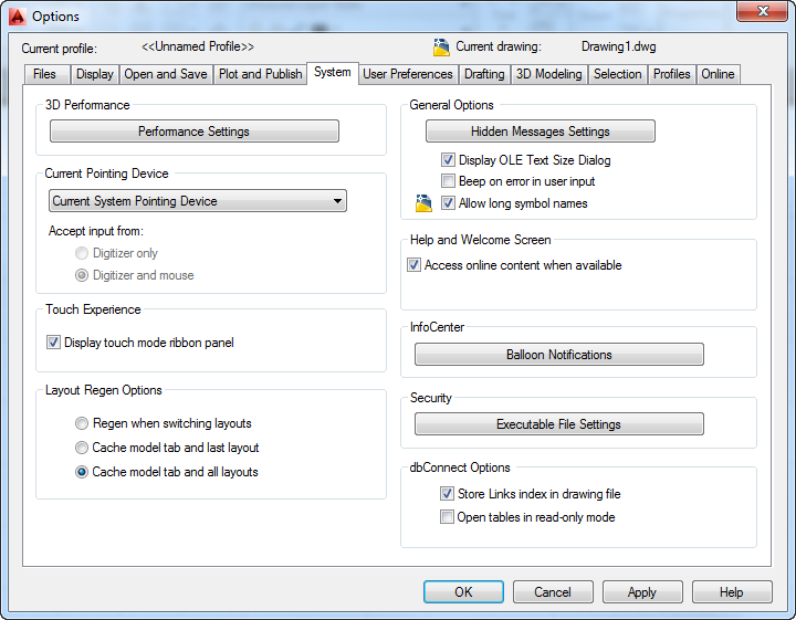
The System Tab
The options in the System tab (see Figure B-4) offer control over some of the general AutoCAD interface settings, such as settings for display drivers and pointing devices.
The 3D Performance Group
Clicking the Performance Settings button in this group displays a variety of settings to help you fine-tune the performance of your 3D graphics. When you click this option, the Adaptive Degradation And Performance Tuning dialog box opens. Adaptive degradation refers to the way the AutoCAD display behaves as you change views such as camera or orbital. AutoCAD degrades the view to keep up with real-time changes in it (thus the term adaptive degradation). You can control how the view degrades using these options. The Hardware And Performance Tuning section gives you information about your current graphic system and allows you to make setting changes. See the section “Adjusting the AutoCAD 3D Graphics System” later in this appendix.
The Current Pointing Device Group
You can choose the type of pointing device you want to use with AutoCAD through the options in this group. The drop-down list offers Current System Pointing Device and Wintab Compatible Digitizer ADI 4.2 – By Autodesk. If you want to use the default Windows pointing device, choose Current System Pointing Device. If you have a digitizer that uses the Wintab driver, you can select Wintab Compatible Digitizer.
You can further limit AutoCAD to use only the Wintab Compatible Digitizer by selecting the Digitizer Only radio button. If you select the Digitizer And Mouse radio button, AutoCAD will accept input from both devices.
The Touch Experience Group
If you are using a touch-enabled PC such as a Windows 8 tablet or ultrabook, the Display touch mode Ribbon panel option will display the Touch Ribbon panel. This panel offers the Select Mode tool, which enables you to cancel the current command.
The Layout Regen Options Group
This set of radio buttons enables you to specify how regens are applied when you are working with layout tabs:
Regen When Switching Layouts Causes AutoCAD to force a regen when you select a layout tab or the Model tab. Use this option when your computer is limited in RAM.
Cache Model Tab And Last Layout Causes AutoCAD to suppress regens when you switch to the Model tab or the most recently opened layout tab. Other layouts will regen when selected.
Cache Model Tab And All Layouts Causes AutoCAD to suppress regens when you select any layout tab or the Model tab.
The General Options Group
This set of check boxes enables you to set options related to the general operation of AutoCAD:
Hidden Messages Settings A number of dialog boxes offer the “Do not show me again” option. If you select it and later find that you would like to see the dialog box again, you can use this button to view the message.
Display OLE Text Size Dialog Lets you control the display of the OLE Text Size dialog box, which normally appears when you insert OLE text objects into an AutoCAD drawing by choosing Paste from the Paste flyout in the Home tab’s Clipboard panel.
Beep On Error In User Input Turns on an alarm beep that sounds whenever there is an input error.
Allow Long Symbol Names Enables you to use long names for items such as layers, blocks, linetypes, and text styles. With this option turned on, you can enter as many as 255 characters for names [Extnames].
The Help And Welcome Screen Group
AutoCAD uses a web-based help system. If for some reason you do not have web access, you can install help files using the AutoCAD 2014 installation tools. The Access Online Content When Available option should be deselected once help files have been installed.
The InfoCenter Group
This group contains just one button: Balloon Notifications. This button opens the InfoCenter Settings dialog box, which gives you control over the behavior of the InfoCenter feature, including balloon notifications, the Live Update channel, the Product Support information channel, and the Did You Know messages.
The Security Group
The Executable File Settings in this group opens the Executable File Settings dialog box, which enables you to set restrictions on how executable files are loaded.
The dbConnect Options Group
The check boxes in this group offer controls over the dbConnect feature:
Store Links Index In Drawing File Lets you specify where database link data is stored. If this check box is selected, link data is stored in the drawing that is linked to a database. This increases file size and file-loading time.
Open Tables In Read-Only Mode Lets you limit access to database files.
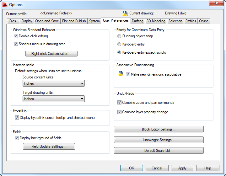
The User Preferences Tab
The options in the User Preferences tab (see Figure B-5) enable you to adjust the way AutoCAD reacts to user input.
The Windows Standard Behavior Group
These settings enable you to control how AutoCAD reacts to keyboard accelerators and mouse right-clicks:
Double Click Editing Controls whether a double-click on an object automatically starts an editing command for the object. If this option is turned off, double-clicking objects has no effect [Dblclkedit].
Shortcut Menus In Drawing Area Lets you see the context menu when you right-click. When this check box isn’t selected, AutoCAD responds to a right-click with a ↵ [Shortcutmenu].
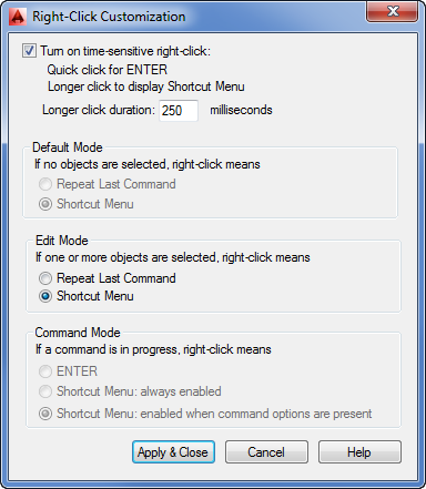
Right-Click Customization Opens the Right-Click Customization dialog box (see
Figure B-6), which offers further options for the behavior of the right-click in AutoCAD. The Turn On Time-Sensitive Right-Click option causes AutoCAD to respond differently depending on whether you right-click quickly or hold the right mouse button down momentarily. With this option, a rapid right-click issues an ↵—as if you pressed the Enter key. If you hold down the right mouse button, the context menu appears. You can further adjust the time required to hold down the mouse button by adjusting this setting.
The Insertion Scale Group
These settings control how DesignCenter or the i-drop feature determines the scale of blocks when blocks are given a unitless setting for their DesignCenter unit type. Each drop-down list offers the standard set of unit types that are available in the Block Definition dialog box under the Insert Units drop-down list. See Chapter 4, “Organizing Objects with Blocks and Groups,” for more information on blocks and Chapter 27 for information on DesignCenter [Insunits, Insunitsdefsource, Insunitsdeftarget].
The Hyperlink Group
The one option in this group turns on or off the display of the hyperlink cursor, tool tip, and context menu [Hyperlinkoptions].
The Fields Group
These settings offer control over the display of fields and how they refresh. Display Background Of Fields lets you control the display of the gray background on fields. This background lets you see at a glance which text object in a drawing is a field. The background doesn’t print. Clicking the Field Update Settings button opens a dialog box that lets you select the action that updates fields [Fielddisplay, Fieldeval].
The Priority for Coordinate Data Entry Group
These options control the way AutoCAD responds to coordinate input:
Running Object Snap Forces AutoCAD to use running osnaps at all times [Osnapcoord].
Keyboard Entry Enables you to use keyboard entry for coordinate input [Osnapcoord].
Keyboard Entry Except Scripts Enables you to use keyboard entry for coordinate input for everything but scripts [Osnapcoord].
The Associative Dimensioning Group
This area has one option, Make New Dimensions Associative, which you can toggle on or off. This option lets you control whether AutoCAD uses the Associative Dimensioning feature. With true associative dimensioning, a dimension follows changes to an object whenever the object is edited. In the old method, you have to include a dimension definition point during the editing process to have the dimension follow changes in an object [Dimassoc].
The Undo/Redo Group
These options control how Undo and Redo react with the Zoom, Pan, and Layer Properties Manager commands.
Block Editor Settings
Click the Block Editor Settings button to open the Block Editor Settings dialog box. This dialog box allows you to control the appearance of objects and features in the Block Editor.
Lineweight Settings
Click the Lineweight Settings button to open the Lineweight Settings dialog box. See Chapter 9, “Understanding Plot Styles,” and Chapter 16 for more information about the Lineweight Settings dialog box.
Default Scale List
Click the Default Scale List button to open the Default Scale List dialog box. You can add your own custom scales for use with viewports and layouts and while plotting.
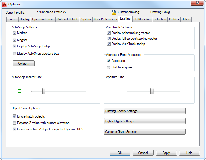
The Drafting Tab
The Drafting tab (see Figure B-7) offers settings that relate to the drawing cursor, including the AutoSnap and AutoTrack features.
The AutoSnap Settings Group
The options in this group control the AutoSnap features that are engaged when you use osnaps:
Marker Turns on the small, square graphic that appears on the osnap location. If you prefer not to see this marker, clear this check box [Autosnap].
Magnet Causes the Osnap cursor to jump to an osnap location as it moves close to that location [Autosnap].
Display AutoSnap Tooltip Controls the display of the osnap tool tip [Autosnap].
Display AutoSnap Aperture Box Displays a square over the cursor whenever osnaps are active. If you’re familiar with earlier versions of AutoCAD, you’ll recognize the aperture box as the graphic used to indicate osnaps before the AutoSnap feature was introduced [Apbox].
Colors Opens the Drawing Window Colors dialog box. Lets you determine the color for the AutoSnap marker and other interface elements.
The AutoSnap Marker Size Group
Move the slider to control the size of the AutoSnap marker.
The Object Snap Options Group
This group offers the Ignore Hatch Objects and Replace Z Value With Current Elevation options. When Ignore Hatch Objects is turned off, osnaps attempt to snap to geometry in hatch patterns. When turned on, Replace Z Value With Current Elevation causes AutoCAD to use the current UCS default Z value instead of the Z value of the selected point. Ignore Negative Z Object Snaps For Dynamic UCS causes osnaps to ignore locations with negative Z values while you’re using the Dynamic UCS feature [Osoptions].
The AutoTrack Settings Group
These options offer control over the tracking vector used for Polar Tracking and Osnap Tracking:
Display Polar Tracking Vector Turns the Polar Tracking vector on or off [Trackpath].
Display Full-Screen Tracking Vector Lets you control whether the tracking vector appears across the full width of the drawing window or stops at the cursor location or the intersection of two tracking vectors [Trackpath].
Display AutoTrack Tooltip Turns the Osnap Tracking tool tip on or off [Autosnap].
The Alignment Point Acquisition Group
These options let you determine the method for acquiring Osnap Tracking alignment points.
The Aperture Size Group
Move the slider to set the size of the osnap aperture pickbox [Aperture].
Drafting Tooltip Settings
Click the Drafting Tooltip Settings button to control the color, size, and transparency of tool tips.
Lights Glyph Settings
Click the Lights Glyph Settings button to control the color and size of the spot and point light glyphs.
Cameras Glyph Settings
Click the Cameras Glyph Settings button to control the color and size of the cameras glyph.
The 3D Modeling Tab
The options on this tab control the behavior and display of your drawing when you’re working in 3D modes. You can adjust the appearance of the crosshair and the UCS icon. You can specify the default method for displaying 3D objects, and you can specify the default settings for Walk And Fly and Animation features.
The 3D Crosshairs Group
These settings control the behavior and appearance of the crosshair cursor when you’re viewing your drawing in 3D:
Show Z-Axis In Crosshairs Displays the z-axis in the crosshair.
Label Axes In Standard Crosshairs Displays the x-, y-, and z-axes’ labels on the crosshair.
Show Labels For Dynamic UCS Displays axis labels during the use of Dynamic UCS regardless of the Label Axes In Standard Crosshairs setting.
Crosshair Labels Lets you select from three label styles: Use X, Y, Z; Use N, E, Z; or Use Custom Labels. If you select Use Custom Labels, you can enter the labels you want to display for the x-, y-, and z-axes in the boxes provided.
The Display Tools in Viewport Group
These three options pretty much explain themselves. Each option determines when the ViewCube®, UCS icon, and Viewport Controls are displayed. By default, they’re all turned on and are always displayed.
The 3D Objects Group
These settings affect the display of 3D objects. Visual Style While Creating 3D Objects is self-explanatory. Deletion Control While Creating 3D Objects lets you determine whether objects AutoCAD uses to create 3D objects are saved or deleted.
The U and V isoline settings let you set the number of isolines on 3D solids and surface meshes. Isolines are the lines you see on a mesh or solid that help you visualize their shape. You see them in wireframe and realistic visual styles [Surfu, Surfv].
The Tessellation button opens the Mesh Tessellation Options dialog box where you can set how the Meshsmooth command affects objects. The Mesh Primitives button opens the Mesh Primitive Options dialog box where you adjust the default mesh primitive settings. The Surface Analysis button lets you make adjustments to the way the surface analysis tools behave.
The 3D Navigation Group
If you want to adjust the way AutoCAD behaves when you’re navigating a 3D view, these settings will help. Reverse Mouse Wheel Zoom is self-explanatory [Zoomwheel]. The remaining four buttons give you control over the behavior of the Walk And Fly feature, the Animation settings, the ViewCube display and behavior, and the SteeringWheels™ display and behavior:
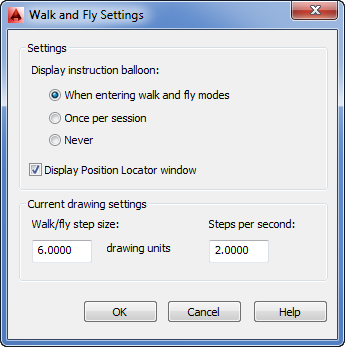
Walk And Fly Click this button to open the Walk And Fly Settings dialog box (see
Figure B-8). When you first start the 3DWalk or 3DFly feature, you see an instructional window that tells you how to use it. You use the options in the Settings group of the Walk And Fly Settings dialog box to specify when that instructional window appears. After using these features a few times, you may find the instructional window annoying and turn it off. You can turn it back on in this dialog box. You can also set the Position Locator window to appear or not appear automatically.
The Current Drawing Settings group lets you set the step size and steps per second when you’re “walking” or “flying” through your model. These are the same settings you see in the Navigate control panel for Step Size and Steps Per Second [Stepsize, Stepspersec].
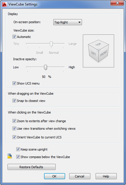
ViewCube Click this button to open the ViewCube Settings dialog box (see
Figure B-9). These settings allow you to control the behavior and appearance of the ViewCube [Navvcubelocation, Navvcubeopacity, Navvcubeorient, Northdirection].
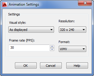
Animation Click this button to open the Animation Settings dialog box (see
Figure B-10). Here you can control the default visual style, resolution, frame rate, and animation file format when using the Motion Path Animation (Anipath) feature.
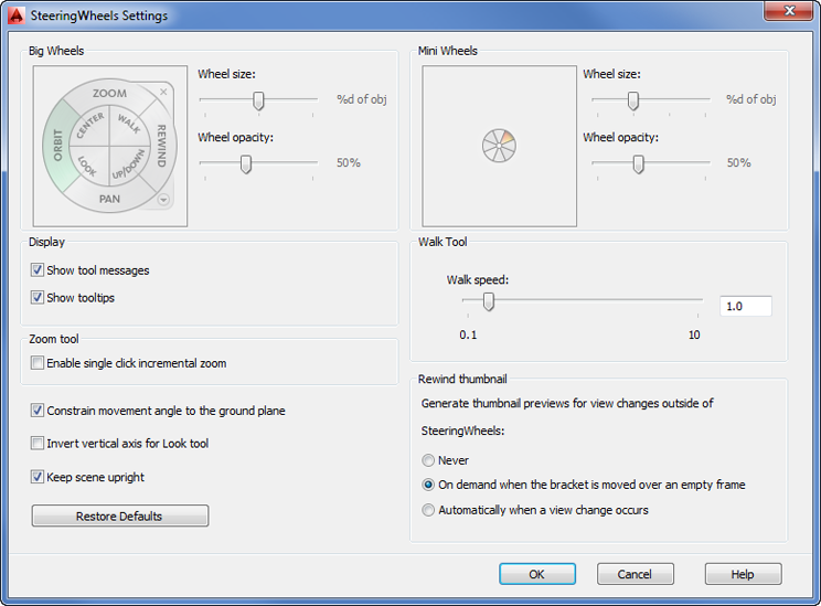
SteeringWheels Click this button to open the SteeringWheels Settings dialog box (see
Figure B-11). Here you can set the appearance and behavior of the SteeringWheels feature [Navwheelsizemini, Navwheelopacitymini].
The Dynamic Input Group
When turned on, the Show Z Field For Pointer Input option offers a z-coordinate for input when Dynamic Input mode is used.
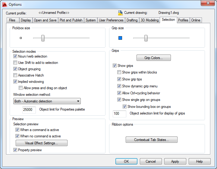
The Selection Tab
The options in the Selection tab of the Options dialog box (see Figure B-12) control the way you select objects in AutoCAD. You can also make adjustments to the Grips feature.
The Pickbox Size Group
This slider control lets you adjust the size of the pickbox [Pickbox].
The Selection Modes Group
These options let you control the degree to which AutoCAD conforms to standard graphical user interface (GUI) methods of operation:
Noun/Verb Selection Makes AutoCAD work more like other Windows programs by letting you select objects before you choose an action or command [Pickfirst].
Use Shift To Add To Selection Lets you use the standard GUI method of holding down the Shift key to select multiple objects. When the Shift key isn’t held down, only the single object picked or the group of objects indicated with a window will be selected. Previously selected objects are deselected unless the Shift key is held down during selection. To turn on this feature by using system variables, set Pickadd to 0 [Pickadd].
Object Grouping Lets you select groups as single objects [Pickstyle].
Associative Hatch Lets you select both a hatch pattern and its associated boundary by using a single pick [Pickstyle].
Implied Windowing Causes a window or crossing window to start automatically if no object is picked at the Select objects: prompt. This setting has no effect on the Noun/Verb setting. In the system variables, set Pickauto to 1 for this option [Pickauto].
Allow Press And Drag On Object Lets you use the standard GUI method for placing window selections. When this option is selected, you click and hold down the Pick button on the first corner of the window. Then, while holding down the Pick button, drag the other corner of the window into position. When the other corner is in place, you let go of the Pick button to finish the window. This setting applies to both Verb/Noun and Noun/Verb operations. In the system variables, set Pickdrag to 1 for this option [Pickdrag].
Window Selection Method Enables you to determine how window selections work. There are three options offered in a drop-down list: Click And Click, Press And Drag, and Both – Automatic Detection. Click And Click places a window by clicking the first corner and then the second. Press And Drag places a window with a press and drag motion of the mouse. Both – Automatic Detection lets you use both Click And Click and Press And Drag depending on whether you click and hold your mouse on the first click [Pickdrag].
Object Limit For Properties Palette Lets you set the limit for the number of objects that can be edited through the Properties palette at one time. The Value range is 0 to 32,767 [Propobjlimit].
The Preview Group
These options let you control the behavior of the selection preview when you hover over objects. Click the Visual Effect Settings button to fine-tune the visual effects of the object selection, including the color and pattern of Autoselect windows and which entities to exclude [Selectionpreview]. The Property Preview toggle determines whether you see a live view of property changes when rolling over drop-down lists and galleries.
The Grip Size Group
This slider control lets you adjust the size of grips [Gripsize].
The Grips Group
These options control the Grips feature:
Grip Colors Lets you select a color for grips in their various states, such as unselected, selected, hovered, and contour [Gripcolor].
Show Grips Controls the display of grips [Grips].
Show Grips Within Blocks Turns on the display of grips in blocks. Although you can’t edit grips in blocks, you can use grips in blocks as selection points [Gripblock].
Show Grip Tips Controls the display of grip tool tips [Griptips].
Show Dynamic Grip Menu Displays a dynamic menu when you’re hovering over a multifunction grip [Gripmultifunctional].
Allow Ctrl+Cycling Behavior Turns on Ctrl+cycling behavior for multifunction grips [Gripmultifunctional].
Show Single Grip On Groups Displays a single grip on groups. When this option is not selected, all of the grips in the set of objects in a group are displayed [Groupdisplaymode].
Show Bounding Box On Groups Displays a bounding box around a selected group [Groupdisplaymode].
Object Selection Limit For Display Of Grips Controls the display of grips based on the number of objects selected. If this is set to 1, grips aren’t displayed if more than one object is selected. You can select a range from 1 to 32,767. The default is 100 [Gripobjlimit].
The Ribbon Options Group
The Contextual Tab States button in the Ribbon Options group opens the Ribbon Contextual Tab State Options dialog box. This dialog box lets you set the conditions under which the Ribbon contextual tabs are displayed. Contextual tabs are Ribbon tabs that offer tools that are designed to edit certain types of objects such as Xrefs or 3D meshes [Ribbonselectmode, Ribboncontextsellim].
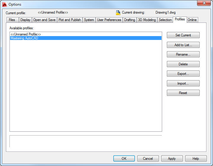
The Profiles Tab
In Windows, a user profile is saved for each login name. Depending on the login name you use, you can have a different Windows setup. The Profiles tab (see Figure B-13) offers a similar function for AutoCAD users. You can store different settings from the Options dialog box in a profile and recall them at any time. You can also save them to a file with the .arg filename extension and then take that file to another system. It’s a bit like being able to take your Options settings with you wherever you go.
The main part of the Profiles tab displays a list of available profiles. The default profile is shown as <<Unnamed Profile>>. As you add more profiles, they appear in the list.
To create a new profile, highlight a profile name from the list that will be the template for the new profile, and then click Add To List. The Add Profile dialog box opens, enabling you to enter a profile name and a description of the profile. The description appears in the box below the list on the Profiles tab whenever that profile is selected.
After you’ve created a new profile, you can modify the settings on the other tabs of the Options dialog box and the new settings will be associated with the new profile. Profiles store the way menus are set up, so you can use them as an aid to managing both your own custom schemes and third-party software. Here is a brief description of the options on the Profiles tab:
Set Current Installs the settings from the selected profile.
Add To List Creates a new profile.
Rename Enables you to rename a profile and change its description.
Delete Removes the selected profile from the list.
Export Lets you save a profile to a file.
Import Imports a profile that has been saved to a file.
Reset Resets the values for a selected profile to its default settings.
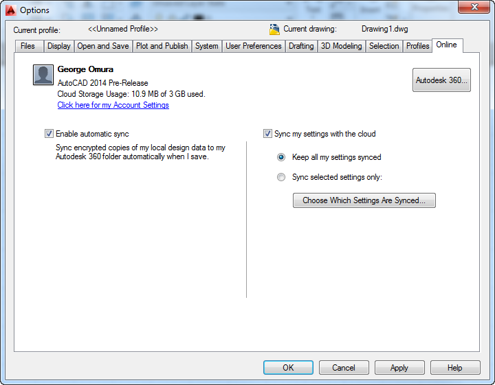
The Online Tab
Autodesk 360 is a feature that allows you to store drawings and AutoCAD settings in a secure, online location. The Online tab enables you to determine the level to which you intend to use Autodesk 360. This tab doesn’t show any options until you sign in to your Autodesk 360 account using the Sign In option in the AutoCAD InfoCenter. Once signed in, you will see the options in the Online tab, shown in Figure B-14.
There are two main settings in the Online tab: Enable Automatic Sync and Sync My Settings With The Cloud. With Enable Automatic Sync turned on, you can have AutoCAD automatically save documents to the cloud.
With the Sync My Settings With The Cloud option turned on, you can have all of your AutoCAD settings saved to the cloud or you can select a set of options to be saved.
If you’d like to learn more about Autodesk 360, see “Sharing Files with Autodesk 360” in Chapter 27.
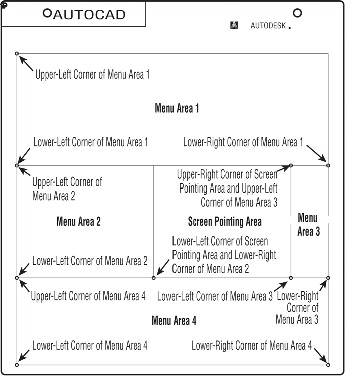
Configuring the Tablet Menu Area
If you own a digitizing tablet and you would like to use it with a Tablet menu template, you must configure your Tablet menu. Install your Tablet menu into AutoCAD using the Menuload command, and then do the following:
1. Securely fasten your Tablet menu template to the tablet. Be sure the area covered by the template is completely within the tablet’s active drawing area.
2. Type
Tablet↵
Cfg↵. The following prompt appears:
Enter number of tablet menus desired (0-4) <0>:
Enter the number of tablet areas your menu uses and then press ↵. For the next series of prompts, you’ll be locating the Tablet menu areas, starting with Menu Area 1.
Figure B-15 shows an example of how to locate the Tablet menu areas for the legacy AutoCAD Tablet menu.
3. Follow the instructions provided by the command-line interface.
4. When you’re asked if you want to respecify the fixed screen pointing area, enter Y↵ and then select the corners of the pointing area as indicated by the prompts.
Turning On the Noun/Verb Selection Method
If for some reason the Noun/Verb Selection method isn’t available, follow these steps to turn it on:
1. Choose Options from the Application menu. Then, in the Options dialog box, click the Selection tab.
2. In the Selection Modes group, click the Noun/Verb Selection check box.
3. Click OK.
You should now see a small square at the intersection of the crosshair cursor. This square is an object selection cursor superimposed on the point selection cursor. It tells you that you can select objects, even while the Command prompt appears at the bottom of the screen and no command is currently active. As you saw earlier, the square momentarily disappears when you’re in a command that asks you to select points.
You can also turn on the Noun/Verb Selection method by entering'Pickfirst↵ at the Type a Command prompt. At the Enter new value for PICKFIRST <0>: prompt, enter 1↵. (Entering 0 turns off the Pickfirst function.) The Pickfirst system variable is stored in the AutoCAD configuration file.
Turning On the Grips Feature
If for some reason the Grips feature isn’t available, follow these steps to turn it on:
1. Choose Options from the Application menu. Then, in the Options dialog box, click the Selection tab.
2. In the Grips group, click the Show Grips check box.
3. Click OK and you’re ready to proceed.
The Selection tab of the Options dialog box also lets you specify whether grips appear on objects that compose a block (see Chapter 4 for more on blocks) as well as set the grip color and size. You can also set these options by using the system variables.
You can also turn the Grips feature on and off by entering 'Grips↵. At the Enter new value for GRIPS <0>: prompt, enter 1 or 2 to turn grips on or 0 to turn grips off. The 2 option turns on grips and displays additional midpoint grips on polyline line segments. The Grips system variable is stored in the AutoCAD configuration file.
Setting Up the Tracking Vector Feature
If AutoCAD doesn’t display a tracking vector as described in the early chapters of this book, or if the tracking vector doesn’t behave as described, chances are this feature has been turned off or altered. Take the following steps to configure the tracking vector so that it behaves as described in this book:
1. Open the Options dialog box by choosing Options from the Application menu.
2. Click the Drafting tab.
3. Click all three options in the AutoTrack Settings group.
4. Make sure the Marker, Magnet, and Display AutoSnap Tooltip check boxes are selected in the AutoSnap Settings group.
5. Make sure the Automatic radio button in the Alignment Point Acquisition group is selected.
6. Click OK to exit the dialog box.
Adjusting the AutoCAD 3D Graphics System
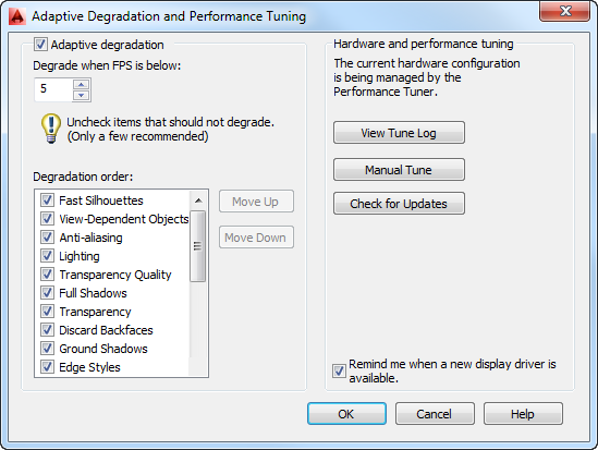
You can adjust the performance of the 3D graphics system in AutoCAD through the Adaptive Degradation And Performance Tuning dialog box (see Figure B-16). To open this dialog box, click the System tab in the Options dialog box and then click the Performance Settings button in the 3D Performance group.
This dialog box offers control over the way AutoCAD displays 3D models when you use the 3D Orbit tool or when you’re using a visual style. The following sections describe the options for the Adaptive Degradation And Performance Tuning dialog box.
The Adaptive Degradation Group
The 3D navigation tools enable you to adjust your view in real time, which places high demands on your display system. To maintain the smoothness of the real-time update of your 3D views, AutoCAD degrades the display while performing the view transformations.
The options in the Adaptive Degradation group let you set the level to which the view is degraded while you’re navigating your model in real time. You can turn off this feature completely by deselecting the Adaptive Degradation check box. If you prefer, you can determine the specific feature to be degraded on an individual basis by deselecting the check box next to an item name in the Degradation Order list box. The Degrade When FPS Is Below setting lets you specify when, in frames per second, the degradation takes effect.
The Hardware and Performance Tuning Group
The Hardware And Performance Tuning group lets you view and adjust your display system’s performance. The View Tune Log button displays the vital statistics for your display system. The Manual Tune button opens the Manual Performance Tuning dialog box. The Check For Updates button takes you to the Autodesk website to allow you to see if new drivers are available for your graphics display card.
The Manual Performance Tuning Dialog Box
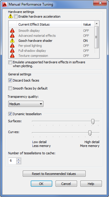
When you click the Manual Tune button in the Adaptive Degradation And Performance Tuning dialog box, the Manual Performance Tuning dialog box opens (see Figure B-17).
The Hardware Settings group lets you determine whether to use hardware acceleration. If you turn on Enable Hardware Acceleration, the “Emulate unsupported hardware effects in software when plotting” option becomes available, and the available features for the selected type of acceleration are displayed in the list box.
The General Settings group offers three options:
Discard Back Faces In most 3D rendering systems, surfaces have just one visible side. The back sides of surfaces are invisible. This doesn’t matter for objects such as cubes and spheres because you see only one side of a surface at any given time, but in some situations, you can see both sides of a surface, such as a single surface used as a wall.
If your drawing is composed of mostly closed objects such as cubes and spheres and you see only one surface, you can select the Discard Back Faces check box to improve system performance. If you have many single surfaces that will be viewed from both sides, you should leave this option turned off.
Smooth Faces By Default If you are importing objects from Autodesk® 3D Studio Max® using the 3DSin command, this option is helpful in displaying PFACE objects smoothly.
Transparency Quality This option lets you control the visual quality of transparent objects in your model when you’re viewing your model in a realistic visual style. You can set transparency to a high-, medium-, or low-quality level. Low-quality levels show transparent objects with a screen-door effect, whereas medium and high options give transparent objects a smoother appearance. The low-quality level allows faster view changes.
The options in the Dynamic Tessellation group determine the smoothness of 3D objects when you use a visual style other than a Wireframe or hidden view. To simulate smoothness, the graphics system divides curved surfaces into triangles called tessellations. You can turn all these features on or off by using the check box next to the group title:
Surfaces Controls the amount of detail shown for surfaces. Greater detail requires more surface tessellation, which in turn requires more system memory.
Curves Controls the amount of detail shown for curved surfaces. Greater detail requires more surface tessellation, which in turn requires more system memory.
Number Of Tessellations To Cache Controls the number of tessellations that are cached. A cache is a part of memory reserved to store frequently used data. AutoCAD always caches one tessellation. Caching two tessellations improves the appearance and performance of 3D objects when you use multiple viewports.
Finding Hidden Folders That Contain AutoCAD Files
Many AutoCAD features rely on external files to store settings and other resources. Many of these files reside in hidden folders. These folders are as follows:
C:Documents and SettingsUser NameApplication
 DataAutodeskAutoCAD 2014R19.1enu
C:Documents and SettingsAll UsersApplication
 DataAutodeskAutoCAD 2014R19.1enu
If you attempt to use Windows Explorer to browse to these locations, you may not find the Application Data folder. You can unhide this folder by doing the following:
1. Right-click the Start button in the lower-left corner of your screen, and then choose Open Windows Explorer.
2. Choose Tools ⇒ Folder Options from the menu bar.
3. In the Folder Options dialog box, select the View tab.
4. In the Advanced Settings list, look for the Hidden Files And Folders option. You see two radio buttons just below this option.
5. Select the Show Hidden Files, Folders And Drives radio button.
6. Click OK to close the Folder Options dialog box.
After you’ve done this, the Application Data folder will be visible and you’ll be able to browse to AutoCAD folders that are found there. Once you’re able to explore these folders, you may want to create a shortcut to them (right-click the folder and choose Create Shortcut). Place the shortcut on your desktop or other convenient location. That way, you can get to them without having to navigate through several layers of folders.
Setting Up AutoCAD with a White Background
As mentioned in the beginning of Chapter 2, “Creating Your First Drawing,” the 2D screen shots in this book are shown with a white background instead of the default dark gray. This is intended to help keep the figures legible in the printed version of this book. You can easily set up your AutoCAD to display the 2D drawing area in the same way by taking the following steps:
1. Open the Application menu and select Options near the bottom of the menu. You can also type Options↵ in the Command window.
2. Select the Display tab in the Options dialog box.
3. Click the Colors button in the Windows Elements group.
4. In the Drawing Window Colors dialog box, make sure 3D parallel projection is selected in the Context settings and that Uniform background is selected in the Interface elements settings.
5. In the Color drop-down list, select white.
6. Select Grid major lines in the Interface element list.
7. In the Color drop-down list, click the Select Color option. In the Select Color dialog box, click the Index Color tab and enter 253 in the Color box. Click OK.
8. Select Grid minor lines in the Interface element list.
9. In the Color drop-down list, click the Select Color option. In the Select Color dialog box, click the Index Color tab and enter 254 in the Color box. Click OK.
10. Click Apply & Close in the Drawing Window Colors dialog box, and then click OK in the Options dialog box.