Chapter 2
Creating Your First Drawing
This chapter examines some of the basic functions of the AutoCAD® software. You’ll get a chance to practice with the drawing editor by building a simple drawing to use in later exercises. You’ll learn how to give input to AutoCAD, interpret prompts, and get help when you need it. This chapter also covers the use of coordinate systems to give AutoCAD exact measurements for objects. You’ll see how to select objects you’ve drawn and how to specify base points for moving and copying.
If you’re not a beginning AutoCAD user, you may want to move on to the more complex material in Chapter 3, “Setting Up and Using the Drafting Tools.” You can use the files supplied at the book’s web page (www.sybex.com/go/masteringautocad2014) to continue the tutorials at that point.
Beginning in this chapter, we’ll be using a setup that displays a white drawing background instead of the dark gray background you see on your screen. We do this to keep the figures legible in the printed version of this book, but the difference should not hinder your understanding of the figures. If you like, you can set up your screen with a white background by following the instructions in Appendix B, “Installing and Setting Up AutoCAD,” in the section “Set Up AutoCAD with a White Background.”
In this chapter, you will learn to:
- Specify distances with coordinates
- Interpret the cursor modes and understand prompts
- Select objects and edit with grips
- Use dynamic input
- Display data in a text window
- Display the properties of an object
- Get help
Getting to Know the Home Tab’s Draw and Modify Panels
Your first task in learning how to draw in AutoCAD software is simply to draw a line. Since AutoCAD is designed as a precision drawing tool, you’ll be introduced to methods that allow you to input exact distances. But before you begin drawing, take a moment to familiarize yourself with the features you’ll be using more than any other to create objects with AutoCAD: the Draw and Modify panels. Try these steps:
1. Start AutoCAD just as you did in Chapter 1, “Exploring the Interface,” by choosing Start ⇒ All Programs ⇒ Autodesk ⇒ AutoCAD 2014 ⇒ AutoCAD 2014.
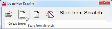
2. If you see the Create New Drawing dialog box, click the Start From Scratch icon and then click OK to go directly to the default Drawing1 document. The Start From Scratch icon looks like a blank page.
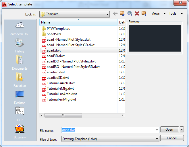
3. If the default
Drawing1.dwg file shows a 3D workspace, click the New tool in the Quick Access toolbar, select
acad.dwt from the Select Template dialog box, and click Open (see
Figure 2-1).
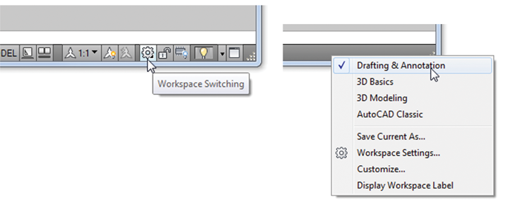
Make sure you are in the Drafting & Annotation workspace by clicking the Workspace Switching tool in the status bar or the Workspace tool in the Quick Access toolbar. If you use the status bar, you should see a check mark next to Drafting & Annotation. If not, click Drafting & Annotation in the list.
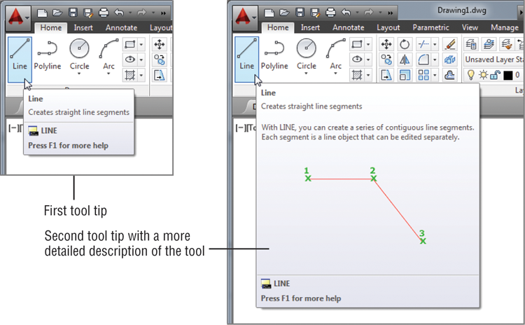
4. Move the arrow cursor to the Line tool in the Home tab’s Draw panel at the far upper-left portion of the AutoCAD window, and rest it there so that the tool tip appears. As you hold the cursor over the tool, first one tool tip appears and then another (see
Figure 2-2).
5. Slowly move the arrow cursor to the right over the other tools in the Home tab’s Draw panel and read each tool tip.
In most cases, you’ll be able to guess what each tool does by looking at its icon. The icon with an arc, for instance, indicates that the tool draws arcs; the one with the ellipse signifies that the tool draws ellipses; and so on. If you hover over the tool, you’ll see the tool tip name and the keyboard command associated with the tool. Hold the cursor for a bit longer and a cue card that gives a brief explanation of how to use the tool appears.
Don’t Get Stuck on the Prompts
In many of the exercises in this book, we’ll mention the Command prompt that appears in the Command window. The prompts are shown for your reference, but don’t let yourself get too bogged down by them. For example, we’ll say, “At the Specify lower left corner or [ON/OFF] <0.0000,0.0000>: prompt, press ↵.” The important part is to “press ↵.” You can skim over the prompt. Just keep in mind that the prompts can offer some direction and show the options for the current command. They can also serve as helpful reminders later when you’re working on your own.
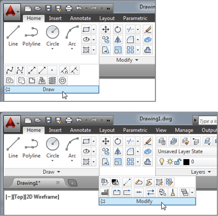
You see several tools in the Home tab’s Draw and Modify panels. In Chapter 1, you saw that if you click the arrow in a panel’s title bar, the panel expands to reveal more tools (see Figure 2-3). Once you’ve selected a tool from the expanded Draw or Modify panel, the expanded panel closes. If you want to keep the expanded panel open, click the pushpin icon at the left end of the expanded panel’s title bar.
Starting Your First Drawing
In Chapter 1, you looked at a preexisting sample drawing. This time, you’ll begin to draw your own drawing by creating a door that will be used in later exercises. First, though, you must learn how to tell AutoCAD what you want, and even more importantly, you must understand what AutoCAD wants from you.
Imperial and Metric
In this chapter, you’ll start to see instructions for both Imperial and metric measurements. In general, you’ll see the instructions for Imperial measurement first, followed by the metric instructions. You won’t be dealing with inches or centimeters yet, however. You’re just getting to know the AutoCAD system.
You’ll start by opening a new drawing and setting the size of the work area, known as the drawing limits. These limits aren’t fixed in any way, and you aren’t forced to stay within the bounds of the drawing limits unless the Limits command’s ON/OFF option is turned on. But limits can help to establish a starting area from which you can expand your drawing.
1. Click the Close icon in the upper-right corner of the drawing area to close the current file. In the AutoCAD dialog box, click No. Notice that the Ribbon disappears and the AutoCAD drawing window appears blank when no drawings are open.
2. Click the New icon in the Quick Access toolbar to open the Select Template dialog box.
3. Select the acad.dwt template, and click Open.
You currently have a new blank file, but it’s a little difficult to tell the size of your drawing area. Let’s set up the work area so you have a better idea of the space with which you’re working:
1. Enter Limits↵.
2. At the Specify lower left corner or [ON/OFF] <0.0000,0.0000>: prompt, press ↵.
3. At the Specify upper right corner <12.0000,9.0000>: prompt, metric users should enter 40,30↵. If you use Imperial units (feet and inches), press ↵ to accept the default of 12.0000,9.0000.
4. Type Z↵A↵ for the Zoom All command. You can also select Zoom All from the Zoom flyout on the Navigation bar.
In the last step, the All option of the Zoom command uses the limits you set up in steps 2 and 3 to determine the display area. In a drawing that contains objects, the Zoom tool’s All option displays the limits plus the area occupied by the objects in the drawing if they happen to fall outside the limits. Now give your file a unique name:
1. Choose Save As from the Application menu or type Saveas↵ to open the Save Drawing As dialog box.
2. Type Door. As you type, the name appears in the File Name text box.
3. Save your file in the My Documents folder, or if you prefer, save it in another folder of your choosing. Just remember where you put it because you’ll use it later.
4. Click Save. You now have a file called Door.dwg, located in the My Documents folder. Of course, your drawing doesn’t contain anything yet. You’ll take care of that next.
Understanding the Drawing Area
The new file shows a drawing area roughly 12 inches wide by 9 inches high. Metric users have a file that shows an area roughly 40 millimeters (mm) wide by 30 mm high. This is just the area you’re given to start with, but you’re not limited to it in any way. No visual clues indicate the size of the area. To check the area size for yourself, move the crosshair cursor to the upper-right corner of the drawing area and observe the value in the coordinate readout in the lower-left corner. The coordinate readout won’t show exactly 12×9 inches, or 40×30 mm for metric, because the proportions of your drawing area aren’t likely to be exactly 12×9 or 40×30. AutoCAD does try to optimize the display for the drawing area when you choose the All option of the Zoom command.
Now you can start to explore the drawing process. To begin a drawing, follow these steps:
1. Click the Line tool on the Home tab’s Draw panel, or type L↵.
You’ve just issued the Line command. AutoCAD responds in two ways. First, you see the message
Specify first point:
in the Command prompt, asking you to select a point to begin your line. Also, the cursor changes its appearance; it no longer has a square in the crosshairs. This is a clue telling you to pick a point to start a line.
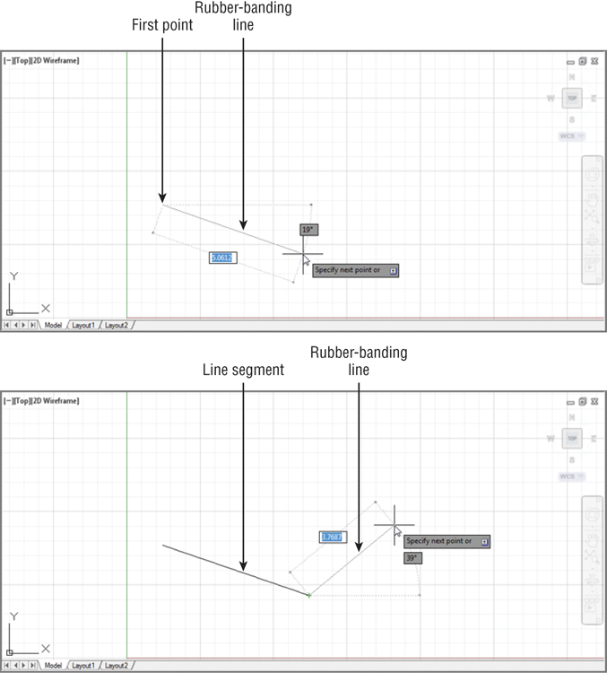
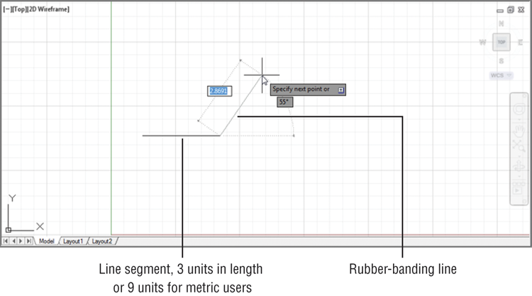
2. Using the left mouse button, select a point on the screen just a little to the left and below the center of the drawing area (
Figure 2-4). After you select the point, AutoCAD changes the prompt to this:
Specify next point or [Undo]:
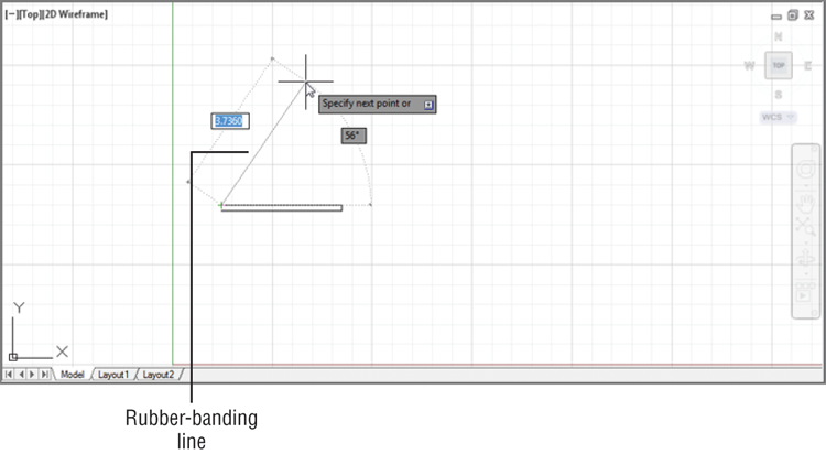
Now, as you move the mouse around, notice the line with one end fixed on the point you just selected and the other end following the cursor in a
rubber-banding motion (see the first image in
Figure 2-4). You also see a message asking you to
Specify next point or.
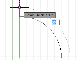
3. Move the cursor to a location directly to the left or right of the point you clicked, and you’ll see a dashed horizontal line appear along with a different message at the cursor. This action also occurs when you point directly up or down. Your cursor seems to jump to a horizontal or vertical position.
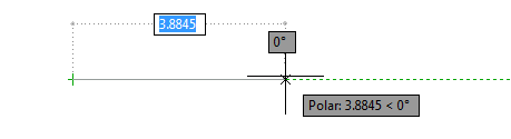
This feature is called Polar Tracking. Like a T square or triangle, it helps to restrict your line to an exact horizontal or vertical direction. You can turn Polar Tracking on or off by clicking the Polar Tracking tool in the status bar. You’ll learn more about this tool in Chapter 3.
4. Continue with the Line command. Move the cursor to a point below and to the right of the first point you selected and click again. You’ve just drawn a line segment, and a second rubber-banding line appears (see the second image in
Figure 2-4).
5. If the line you drew isn’t the exact length you want, you can back up during the Line command and change it. To do this, type U↵. The line you drew previously rubber-bands as if you hadn’t selected the second point to fix its length.
6. Right-click and select Enter. This terminates the Line command.
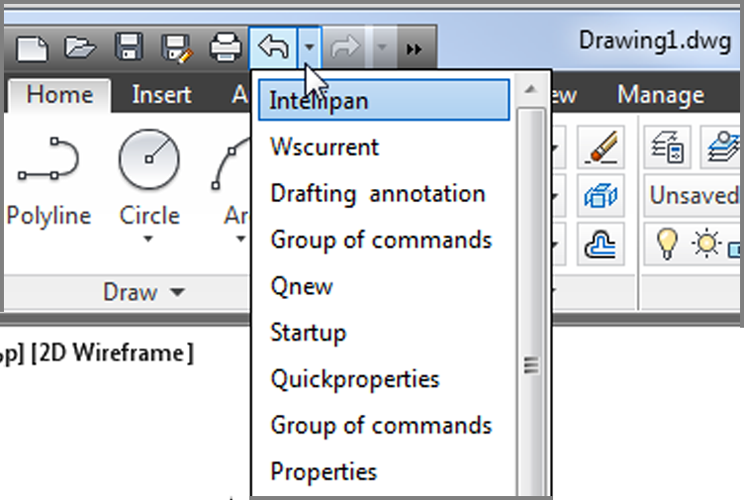
The Undo and Redo tools in the Quick Access toolbar offer Undo and Redo drop-down lists from which you can select the exact command you want to undo or redo. See the sidebar “Getting Out of Trouble” later in this chapter for more information.
You’ve just drawn, and then undrawn, a line of an arbitrary length. The Line command is still active. Two onscreen clues tell you that you’re in the middle of a command. If you don’t see the words Type a Command in the Command window, a command is still active. Also, the cursor is the plain crosshair without the box at its intersection.
From now on, we’ll refer to the crosshair cursor without the small box as the Point Selection mode of the cursor. If you look ahead to Figure 2-5, you’ll see all the modes of the drawing cursor.
Why Use the Keyboard Commands?
For many years, Autodesk has been encouraging users to move away from the command line and keyboard method of command entry, but it seems that AutoCAD users will have none of that. Although you would expect “grizzled veteran” users to stick with the keyboard entry method, you might be surprised to find that young “fresh out of school” apprentice architects also prefer the keyboard over the newer palettes and ribbons in AutoCAD.
We made this observation to one of the designers of AutoCAD at a recent Autodesk function. Without hesitation, he answered that “keyboard entry is much faster.” In our experience, it isn’t just faster. Entering commands via the keyboard gives you a more “connected” feeling with AutoCAD. Work seems to flow much smoother. If you learn the keyboard commands, you’ll also find that customizing AutoCAD is much easier. So for these reasons, we encourage you to try both the keyboard and the buttons to see which you prefer. You’ll find that, wherever possible, we’ll give the keyboard command equivalent to a tool selection in the exercises of this book. Remember that a tool’s tool tip will also show its keyboard command.
Specifying Exact Distances with Coordinates
Next, you’ll continue with the Line command to draw a plan view (an overhead view) of a door, to no particular scale. This will give you some practice in drawing objects to exact distances. Later, you’ll resize the drawing for use in future exercises. The door will be 3 units long and 0.15 units thick. For metric users, the door will be 9 units long and 0.5 units thick. To specify these exact distances in AutoCAD, you can use either relative polar coordinates or Cartesian coordinates.
Getting Out of Trouble
Beginners and experts alike are bound to make a few mistakes. Before you get too far into the exercise, here are some powerful but easy-to-use tools to help you recover from accidents:
Backspace If you make a typing error, press the Backspace key to back up to your error and then retype your command or response. The Backspace key is in the upper-right corner of the main keyboard area.
Escape (Esc) This is perhaps the single most important key on your keyboard. When you need to exit a command or a dialog box quickly without making changes, press the Esc key in the upper-left corner of your keyboard. In most cases, you need to press Esc only once, although it won’t hurt to press it twice. (Press Esc before editing with grips or issuing commands through the keyboard.)
U If you accidentally change something in the drawing and want to reverse that change, click the Undo tool in the Quick Access toolbar (the left-pointing curved arrow). You can also type U↵ at the Command prompt. Each time you do this, AutoCAD undoes one operation at a time, in reverse order. The last command performed is undone first, then the next-to-last command, and so on. The prompt displays the name of the command being undone, and the drawing reverts to its state prior to that command being issued. If you need to, you can undo everything back to the beginning of an editing session. You can also select the exact command to back up to by using the Undo drop-down list in the Quick Access toolbar.
You can open the Undo drop-down list by clicking the down-pointing arrow found to the right of the Undo tool.
Undo If you want more control over the way Undo works, you can use the Undo command, which allows you to “bookmark” places in your editing session that you can “undo” to. Type Undo↵ and you’ll see the Enter the number of operations to undo or [Auto/Control/BEgin/End/Mark/Back] <1>: prompt. You can enter a number indicating the number of steps you want to undo. Use the Mark option to bookmark a location; then use Back to undo your work to that bookmark. You can use Begin and End to mark the beginning and end of a set of operations that will be undone all at once. Control offers options to control the behavior of the Undo command. Auto is an option that is on by default and causes AutoCAD to undo the action of the whole command rather than the individual actions within a command.
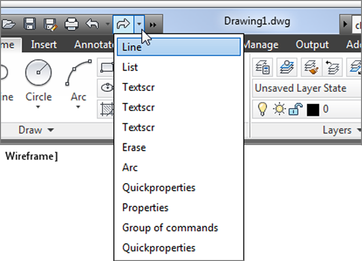
Redo If you accidentally undo one too many commands, you can redo the last undone command by clicking the Redo tool (the right-pointing curved arrow) in the Quick Access toolbar, or you can type Redo↵. You can redo several operations that you may have undone with the Undo command. You can also select the exact command to redo to by using the Redo drop-down list in the Quick Access toolbar.
Oops If you’ve deleted something and gone on to use other commands, you can restore the last deleted object or objects by using the Oops command. Oops enables you to restore the last deleted set of objects without having to undo a series of commands.
The Imperial and metric distances aren’t equivalent in the exercises in this chapter. For example, 3 units in the Imperial-based drawing aren’t equal to 9 metric units. These distances are arbitrary and based on how they appear in the figures in this chapter.
Specifying Polar Coordinates
To enter the exact distance of 3 (or 9 metric) units to the right of the last point you selected, do the following:
1. Click the Line tool on the Home tab’s Draw panel, or type L↵.
2. Click a point slightly to the left of the center of the drawing area to select the start point.
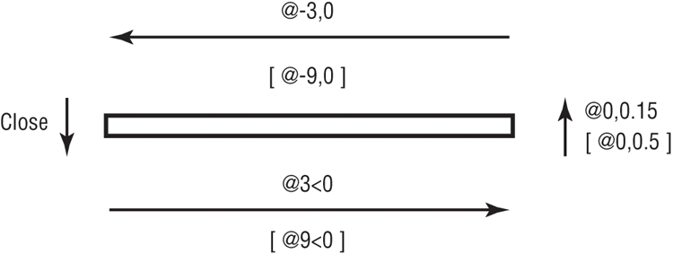
3. Type @3<0. Metric users should type @9<0. As you type, the letters appear at the Command prompt.
4. Press ↵. A line appears, starting from the first point you picked and ending 3 units to the right of it (see
Figure 2-6). You’ve just entered a relative polar coordinate.
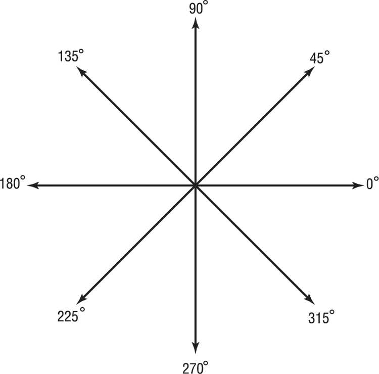
The “at” sign (@) you entered tells AutoCAD that the coordinate you’re specifying is from the last point you selected. The 3 (or 9 metric) is the distance, and the less-than symbol (<) tells AutoCAD that you’re designating the angle at which the line is to be drawn. The last part is the value for the angle, which in this case is 0 for 0°. This is how to use polar coordinates to communicate distances and directions to AutoCAD.
If you’re accustomed to a different method for describing directions, you can set AutoCAD to use a vertical direction or downward direction as 0°. See Chapter 3 for details.
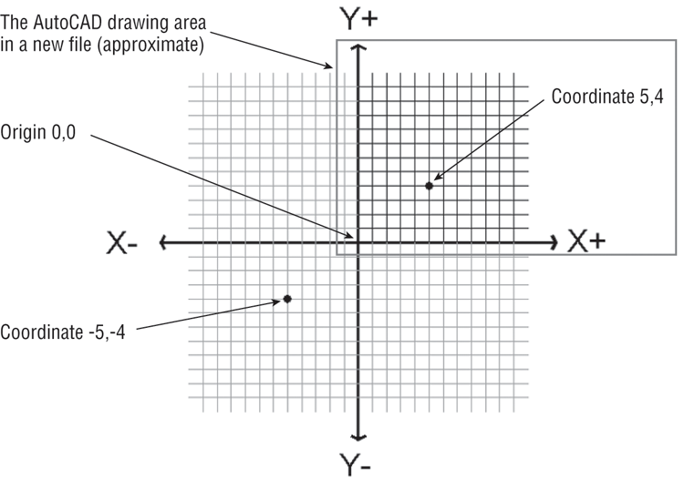
Angles are given based on the system shown in Figure 2-7, in which 0° is a horizontal direction from left to right, 90° is straight up, 180° is horizontal from right to left, and so on. You can specify degrees, minutes, and seconds of arc if you want to be that exact. You can also specify angles using negative values, which would mirror the direction about the x-axis. For example, a minus 45° angle would point in the direction shown as 315° in Figure 2-7. We’ll discuss angle formats in more detail in Chapter 3.
Specifying Relative Cartesian Coordinates
For the next line segment, let’s try another method for specifying exact distances:
1. Enter @0,0.15↵. Metric users should enter @0,0.5↵. A short line appears above the endpoint of the last line. Once again, @ tells AutoCAD that the coordinate you specify is from the last point picked. But in this example, you give the distance in X and Y values. The X distance, 0, is given first, followed by a comma, and then the Y distance, 0.15 or 0.5. This is how to specify distances in relative Cartesian coordinates.
Commas and Periods
Step 1 indicates that metric users should enter @0,0.5↵ for the distance. Instead, you could enter @0,.5 (zero comma point five). The leading zero is included for clarity. European metric users should be aware that the comma is used as a separator between the X and Y components of the coordinate. In AutoCAD, commas aren’t used for decimal points; you must use a period to denote a decimal point.
2. Enter
@-3,0↵. Metric users should enter
@-9,0↵. This distance is also in X,Y values, but here you use a negative value to specify the X distance. The result is a drawing that looks like
Figure 2-8.
Positive values in the Cartesian coordinate system are from left to right and from bottom to top (see
Figure 2-9). (You may remember this from your high school geometry class!) If you want to draw a line from right to left, you must designate a negative value. It’s also helpful to know where the origin of the drawing lies. In a new drawing, the origin—or coordinate 0,0—is in the lower-left corner of the drawing.
3. Type
C↵. This
C stands for the Close option. You can also click the Close option in the command line or right-click and select Close from the context menu. A line connecting the first and last points of a sequence of lines is drawn (see
Figure 2-10), and the Line command terminates. The rubber-banding line also disappears, telling you that AutoCAD has finished drawing line segments. You can also use the rubber-banding line to indicate direction while simultaneously entering the distance through the keyboard. See the sidebar “Other Ways to Enter Distances” later in this chapter.
To finish drawing a series of lines without closing them, you can press Esc, ↵, or the spacebar.
Interpreting the Cursor Modes and Understanding Prompts
The key to working with AutoCAD successfully is understanding the way it interacts with you. The following sections will help you become familiar with some of the ways AutoCAD prompts you for input. Understanding the format of the messages in the Command window and recognizing other events on the screen will help you learn the program more easily.
Understanding Cursor Modes
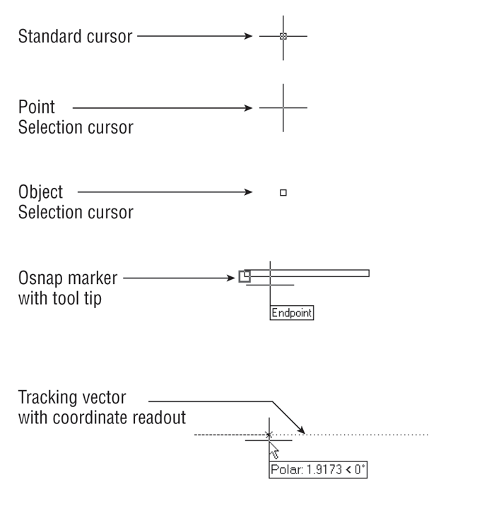
As the Command window aids you with messages, the cursor gives you clues about what to do. Figure 2-5 earlier illustrates the various modes of the cursor, and it gives a brief description of the role of each mode. Take a moment to study this figure.
The Standard cursor tells you that AutoCAD is waiting for instructions. You can also edit objects by using grips when you see this cursor. Grips are squares, rectangles, or arrowheads that appear at endpoints and at the midpoint of objects when they’re selected. (You might know them as workpoints from other graphics programs.)
The Point Selection cursor appears whenever AutoCAD expects point input. It can also appear in conjunction with a rubber-banding line. You can either click a point or enter a coordinate through the keyboard.
The Object Selection or Pickbox cursor tells you that you must select objects—either by clicking them or by using any of the object-selection options available.
The osnap (object snap) marker appears along with the Point Selection cursor when you invoke an osnap. Osnaps let you accurately select specific points on an object, such as endpoints or midpoints.
The tracking vector appears when you use the Polar Tracking or Object Snap Tracking feature. Polar Tracking aids you in drawing orthogonal lines, and Object Snap Tracking helps you align a point in space relative to the geometry of existing objects. Object Snap Tracking works in conjunction with osnaps. You’ll learn more about the tracking vector in Chapter 3.

If you’re an experienced AutoCAD user, you may prefer to use the old-style crosshair cursor that crosses the entire screen. Choose Options from the bottom of the Application menu to open the Options dialog box, and then click the Display tab. Set the Crosshair Size option near the bottom right of the dialog box to 100. The cursor then appears as it did in previous versions of AutoCAD. As the option name implies, you can set the crosshair size to any percentage of the screen you want. The default is 5 percent.
Other Ways to Enter Distances
A third method for entering distances is to point in a direction with a rubber-banding line and then enter the distance through the keyboard. For example, to draw a line 3 units long from left to right, click the Line tool on the Home tab’s Draw panel, click a start point, and then move the cursor so the rubber-banding line points to the right at some arbitrary distance. With the cursor pointing in the direction you want, type 3↵. The rubber-banding line becomes a fixed line 3 units long. Using this method, called the Direct Distance method, along with the Ortho mode or Polar Tracking described in Chapter 3, can be a fast way to draw orthogonal lines of specific lengths.
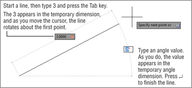
You can also specify an exact angle along with the distance. For example, start the Line command and then pick the first point. Type 3 for the length but don’t press ↵. Press the Tab key instead. The line segment will become fixed at 3 units, and as you move the cursor, the segment will rotate freely around the first point. Next, type an angle in degrees, 30↵ for example, and the line will be drawn at 30 degrees. Or, instead of typing in an angle, just adjust the angle of the line visually until you see the angle you want on the Dynamic Input temporary angle dimension and then click the mouse.
If you watch the temporary dimensions as you press the Tab key, you’ll see that the Tab key lets you move from the length dimension to the angle dimension and back again. You can press the Tab key at any time to shift back and forth between dimensions. A lock appears next to a dimension that you have entered, telling you that the dimension is “locked” until you tab to it again.
You’ll learn more about how to enter values with the Dynamic Input’s temporary dimensions later in this chapter.
Choosing Command Options
Many commands in AutoCAD offer several options, which are often presented to you in the Command window in the form of a prompt. This section uses the Arc command to illustrate the format of AutoCAD prompts.
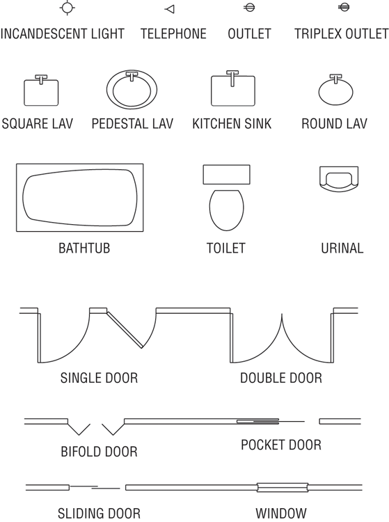
Usually, in a floor-plan drawing in the United States, an arc is drawn to indicate the direction of a door swing. Figure 2-11 shows other standard symbols used in architectural-style drawings.
Here, you’ll draw the arc for the door you started in the previous exercise:
1. Click the 3-Point Arc tool in the Home tab’s Draw panel. Click the Arc flyout and select 3-Point. The Specify start point of arc or [Center]: prompt appears in the Command window, and the cursor changes to Point Selection mode. You also see the prompt Specify start point of arc or prompt next to the cursor.
Examine the Specify start point of arc or [Center]: prompt. The prompt contains two options. The default option is the one stated in the main part of the prompt. In this case, the default option is to specify the start point of the arc. If other options are available, they appear within square brackets. In the Arc command, you see the word Center within brackets telling you that, if you prefer, you can also start your arc by selecting a center point instead of a start point. If multiple options are available, they appear within the brackets and are set off with a slightly darker background. This background tells you that the option is selectable using your cursor and also aids in separating option names. The default is the option AutoCAD assumes you intend to use unless you tell it otherwise.
2. Type C↵ to select the Center option or click the word Center in the command line. The Specify center point of arc: prompt appears. Notice that you had to type only the C and not the entire word Center.
When you see a set of options in the Command window, note their capitalization. If you choose to respond to prompts by using the keyboard, these capitalized letters are all you need to enter to select the option. In some cases, the first two letters are capitalized to differentiate two options that begin with the same letter, such as LAyer and LType. You can also just click the option name in the Command prompt to select the option.
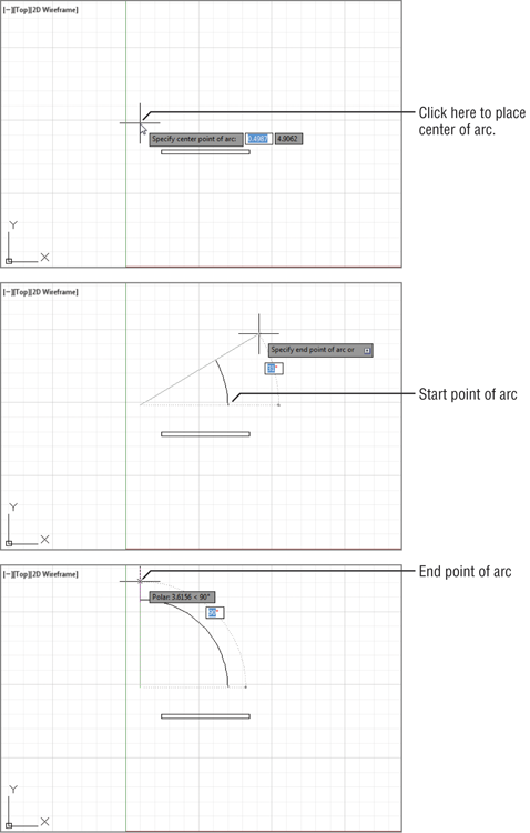
3. Pick a point representing the center of the arc near the upper-left corner of the door (see
Figure 2-12). The
Specify start point of arc: prompt appears.
4. Type @3<0↵. Metric users should type @9<0↵.The Specify end point of arc or [Angle chord Length]: prompt appears.
5. Move the mouse and a temporary arc appears, originating from a point 3 units to the right of the center point you selected and rotating about that center, as shown in
Figure 2-12. (Metric users will see the temporary arc originating 9 units to the right of the center point.)
As the prompt indicates, you now have three options. You can enter an angle, a chord length, or the endpoint of the arc. The prompt default, to specify the endpoint of the arc, picks the arc’s endpoint. Again, the cursor is in Point Selection mode, telling you it’s waiting for point input. To select this default option, you only need to pick a point on the screen indicating where you want the endpoint.
6. Move the cursor so that it points in a vertical direction from the center of the arc. You’ll see the Polar Tracking vector snap to a vertical position.
7. Click any location with the Polar Tracking vector in the vertical position. The arc is now fixed in place, as shown in
Figure 2-12.
This exercise has given you some practice working with AutoCAD Command window prompts and entering keyboard commands—skills you’ll need when you start to use some of the advanced AutoCAD functions.
As you can see, AutoCAD has a distinct structure in its prompt messages. You first issue a command, which in turn offers options in the form of a prompt. Depending on the option you select, you get another set of options or you’re prompted to take some action, such as picking a point, selecting objects, or entering a value.
As you work through the exercises, you’ll become intimately familiar with this routine. After you understand the workings of the Ribbon panels, the Command window prompts, and the dialog boxes, you can almost teach yourself the rest of the program!
Using AutoComplete and AutoCorrect
You may have noticed that as you enter a command through the keyboard, the Command window offers suggestions to complete your typing in a way similar to many web browsers. For example, if you type LI, a list pops up offering a number of commands that start with LI. You can then click the option that you want to use. This feature can be helpful when you forget the full name of a command.
AutoCorrect works in a similar way, but instead of offering a list of commands that start with the letters you type, AutoCAD will try to “correct” a mistyped command. For example, if you type crl, AutoCAD will display several commands that come close to what you typed.
You can also control how the AutoComplete and AutoCorrect features work. Right-click in the Command window, and then point to the Input Settings option that appears in the context menu. You can then toggle several options on or off. The options are AutoComplete, AutoCorrect, Search System Variables, Search Content, Mid-string Search, and Delay Time.
Selecting Options from a Context Menu
Now you know that you can select command options by typing them. You can also right-click at any time during a command to open a context menu containing those same options. For example, in step 2 in the previous exercise, you typed C↵ to tell AutoCAD that you wanted to select the center of the arc. Instead of typing, you can also right-click the mouse to open a menu of options applicable to the Arc command at that time.
In addition to the options shown in the Command prompt, the context menu shows you a few more: Enter, Cancel, Pan, and Zoom. The Enter option is the same as pressing ↵. Cancel cancels the current command. Pan and Zoom let you adjust your view as you’re working through the current command.
The menu is context sensitive, so you see only those options that pertain to the command or activity that is currently in progress. Also, when AutoCAD is expecting a point, an object selection, or a numeric value, right-clicking doesn’t display a context menu. Instead, AutoCAD treats a right-click as ↵.
The location of your cursor when you right-click determines the contents of the list of available operations. A right-click in the Command window displays a list of operations you can apply to the command line, such as repeating one of the last several commands you’ve used or copying the most recent history of command activity to the Clipboard.
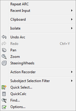
A right-click in the drawing area when no command is active displays a set of basic options for editing your file, such as the command most recently used, Undo, Redo, Pan, and Zoom to name a few (see Figure 2-13). The Cut, Copy, and Paste commands can be found under the Clipboard option.
If you’re ever in doubt about what to do in AutoCAD, you can right-click to see a list of options. You’ll learn more about these options later in this book. For now, let’s move on to the topic of selecting objects.
How We’ll Show Command Options
As mentioned earlier, the options in the command line are shown with a slightly darker background color so you can easily determine the name of the options (see Figure 2-14).
Unfortunately, it’s a bit more difficult to show the options in the same way in this book, so from now on, when we show the command options, we’ll use a forward slash mark to separate the options. For example, in the Arc command options discussed earlier, you saw this command prompt:
Specify end point of arc or [Angle chord Length]
We’ll show it like this, using the / symbol to separate the command options:
Specify end point of arc or [Angle/chord Length]
Without the / symbol, you might confuse the option names as Angle chord and Length, or you may even think that there are three options named Angle, chord, and Length. Those of you familiar with older versions of AutoCAD will recognize this use of the / symbol as the way AutoCAD used to separate command options in the command line.
Selecting Objects
In AutoCAD, you can select objects in many ways. The following sections cover two ways: The first covers object-selection methods unique to AutoCAD, and the second covers the more common selection method used in most popular graphics programs, the Noun/Verb method. Because these two methods play a major role in working with AutoCAD, it’s a good idea to familiarize yourself with them early on.
If you need to select objects by their characteristics rather than by their location, see Chapter 15, “Advanced Editing and Organizing,” which describes the Quick Select and Object Selection Filters tools. These tools let you easily select a set of objects based on their properties, including object type, color, layer assignment, and so on.
Selecting Objects in AutoCAD
With many AutoCAD commands, you’ll see the Select objects: prompt. Along with this prompt, the cursor changes from crosshairs to the Object Selection cursor (look back at Figure 2-5). Whenever you see the Select objects: prompt and the square Pickbox cursor, you have several options while making your selection. Often, as you select objects on the screen, you’ll change your mind about a selection or accidentally select an object you don’t want. Let’s look at most of the selection options available in AutoCAD and learn what to do when you make the wrong selection.
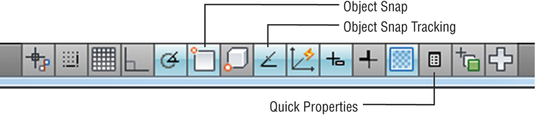
Before you continue, you’ll turn off two features that, although extremely useful, can be confusing to new users. These features are called Running Osnaps and Osnap Tracking. You’ll get a chance to explore these features in depth later in this book, but for now follow these steps to turn them off:
1. Check to see if either Object Snap or Object Snap Tracking is turned on in the status bar. If they’re turned on, they will be a light blue. Also make sure Quick Properties is off.
2. To turn off Object Snap, click the tool in the status bar. When turned off, it will change to gray.
Now, let’s see how to select an object in AutoCAD:
1. Choose Move from the Home tab’s Modify panel, or type M↵.
2. At the
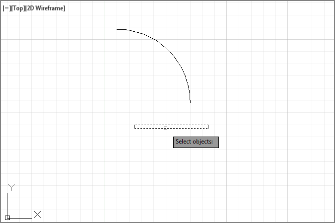
Select objects: prompt, click each of the two horizontal lines that constitute the door. As you know, whenever AutoCAD wants you to select objects, the cursor turns into the small square pickbox. This tells you that you’re in Object Selection mode. As you place the cursor over an object, it appears thicker to give you a better idea of what you’re about to select. As you click an object, it’s highlighted, as shown in
Figure 2-15.
If objects don’t become “thicker” as you roll over them with your selection cursor, the Selection preview system variable may be turned off. You can turn it back on by entering selectionpreview↵3↵. This setting can also be found in the Selection tab of the Options dialog box. See Appendix B for more on the Options dialog box, and see Bonus Chapter 4, “System Variables and Dimension Styles,” for more on system variables.
3. After making your selections, you may decide to deselect some items. Enter U↵ from the keyboard. Notice that one line is no longer highlighted. When you type U↵, objects are deselected, one at a time, in reverse order of selection.
4. You can deselect objects in another way. Hold down the Shift key and click the remaining highlighted line. It reverts to a solid line, showing you that it’s no longer selected for editing.
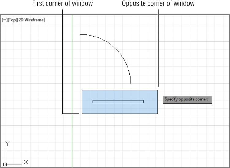
5. By now, you’ve deselected both lines. Let’s try another method for selecting groups of objects. To select objects with a window selection, type
W↵. The cursor changes to a Point Selection cursor, and the prompt changes to
Specify first corner:
6. Click a point below and to the left of the rectangle representing the door. As you move your cursor across the screen, a selection window appears and stretches across the drawing area. Also notice that the window has a blue tint.
7. After the selection window completely encloses the door but not the arc, click this location to highlight the entire door. This window selects only objects that are completely enclosed by the window, as shown in
Figure 2-16.
Don’t confuse the selection window you’re creating here with the zoom window you used in Chapter 1, which defines an area of the drawing you want to enlarge. Remember that the Window option works differently under the Zoom command than it does for other editing commands.
8. Press ↵. This tells AutoCAD that you’ve finished selecting objects. It’s important to remember to press ↵ as soon as you finish selecting the objects you want to edit. A new prompt, Specify base point or [Displacement] <Displacement>:, appears. The cursor changes to its Point Selection mode.
Now you’ve seen how the selection process works in AutoCAD—but you’re in the middle of the Move command. The next section discusses the prompt that’s on your screen and describes how to enter base points and displacement distances.
Providing Base Points
When you move or copy objects, AutoCAD prompts you for a base point, which is a difficult concept to grasp. AutoCAD must be told specifically from where and to where the move occurs. The base point is the exact location from which you determine the distance and direction of the move. After the base point is determined, you can tell AutoCAD where to move the object in relation to that point.
Follow these steps to practice using base points:
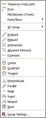
1. To select a base point, press Shift+right-click. A menu appears, displaying the Object Snap options (see
Figure 2-17).
When you right-click the mouse, make sure the cursor is within the AutoCAD drawing area; otherwise, you won’t get the results described in this book.
2. Choose Intersection from the Object Snap menu. The Object Snap menu closes.
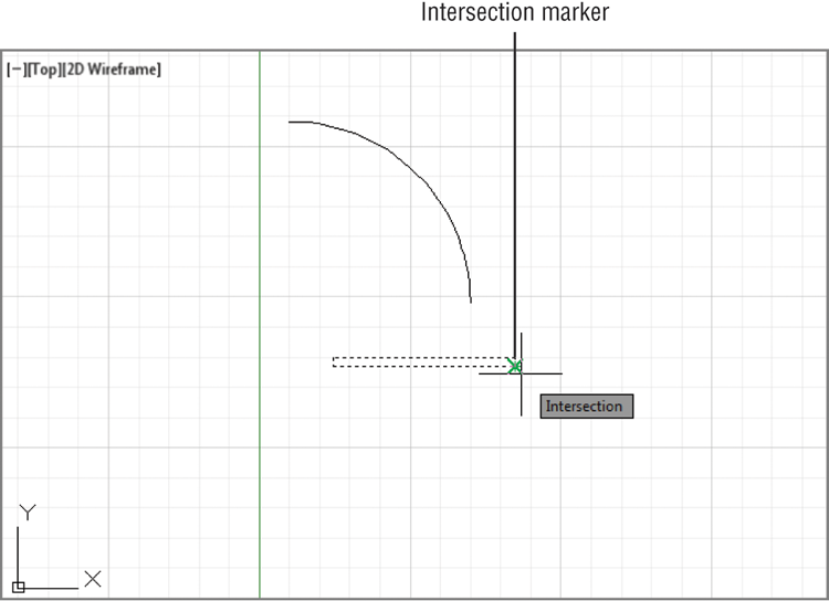
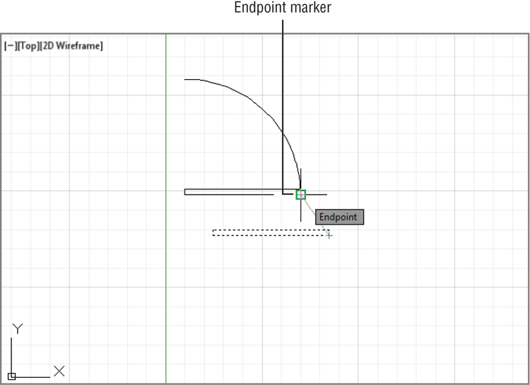
3. Move the cursor to the lower-right corner of the door. Notice that as you approach the corner, a small x-shaped graphic appears on the corner. This is called an osnap marker.
4. After the x-shaped marker appears, hold the mouse motionless for a second or two. A tool tip appears, telling you the current osnap point AutoCAD has selected.
5. Click the left mouse button to select the intersection indicated by the osnap marker. Whenever you see the osnap marker at the point you want to select, you don’t have to point exactly at the location with your cursor. Just left-click the mouse to select the exact osnap point (see
Figure 2-18). In this case, you selected the exact intersection of two lines.
6. At the Specify second point or <use first point as displacement>: prompt, hold down the Shift key and right-click again to open the Object Snap menu.
7. This time you’ll use the Endpoint osnap, but instead of clicking the option with the mouse, type E.
8. Pick the lower-right end of the arc you drew earlier. (Remember that you need to move your cursor close to the endpoint just until the osnap marker appears.) The door moves so that the corner connects exactly with the endpoint of the arc (see
Figure 2-19).
As you can see, the osnap options let you select specific points on an object. You used Endpoint and Intersection in this exercise, but other options are available. Chapter 3 discusses some of the other osnap options. You may have also noticed that the osnap marker is different for each of the options you used. You’ll learn more about osnaps in Chapter 3. Now let’s continue with our look at point selection.
You may have noticed the statement Use first point as displacement in the prompt in step 6 of the preceding exercise. This means that if you press ↵ instead of clicking a point, the object will move a distance based on the coordinates of the point you selected as a base point. If, for example, the point you click for the base point is at coordinate 2,4, the object will move 2 units in the x-axis and 4 units in the y-axis.
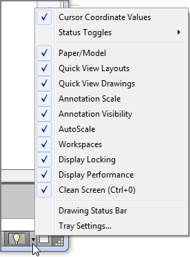
Controlling the Status Bar Display
Toward the right of the status bar, you’ll see a down-pointing arrow. This arrow opens a menu that controls the display of the status bar. You use this menu to turn the items in the status bar on or off. A check mark by an item indicates that it’s currently on. If for some reason you don’t see all the buttons mentioned in the previous exercise, check this menu to make sure all the status bar options are turned on. For the items in the left half of the status bar, choose Status Toggles from the menu. Note that AutoCAD LT doesn’t have an Otrack option in the status bar.
If you want to specify an exact distance and direction by typing a value, select any point on the screen as a base point. As an alternative, you can type @ followed by ↵ at the base point prompt; then, enter the second point’s location in relative coordinates. Remember that @ means the last point selected. In the next exercise, you’ll try moving the entire door an exact distance of 1 unit at a 45° angle. Metric users will move the door 3 units at a 45° angle. Here are the steps:
1. Click the Move tool on the Home tab’s Modify panel.
2. Type P↵. The set of objects you selected in the previous exercise is highlighted. P is a selection option that selects the previously selected set of objects.
3. You’re still in Object Selection mode, so click the arc to include it in the set of selected objects. The entire door, including the arc, is highlighted.
4. Press ↵ to tell AutoCAD that you’ve finished your selection. The cursor changes to Point Selection mode.
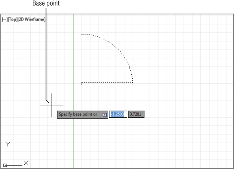
5. At the
Specify base point or [Displacement] <Displacement>: prompt, choose a point on the screen between the door and the left side of the screen (see
Figure 2-20).
6. Move the cursor around slowly and notice that the door moves as if the base point you selected were attached to it. The door moves with the cursor, at a fixed distance from it. This demonstrates how the base point relates to the objects you select.
7. Type @1<-45↵. (Metric users should type @3<-45↵.) The door moves to a new location on the screen at a distance of 1 unit (3 for metric users) from its previous location and at an angle of minus 45°, which is a direction that is downward at a 45 degree angle.
If AutoCAD is waiting for a command, you can repeat the last command used by pressing the spacebar or pressing ↵. You can also right-click in the drawing area and select the option at the top of the list. If you right-click the Command window, a context menu offers the most recent commands.
This exercise illustrates that the base point doesn’t have to be on the object you’re manipulating; it can be virtually anywhere on your drawing. You also saw how to reselect a group of objects that were selected previously without having to duplicate the selection process.
Using Noun/Verb Selection
Nearly all graphics programs today allow the Noun/Verb method for selecting objects. This method requires you to select objects before you issue a command to edit them—that is, you identify the “noun” (the object you want to work on) before the “verb” (the action you want to perform on it). The following exercises show you how to use the Noun/Verb method in AutoCAD.
You’ve seen that when AutoCAD is waiting for a command, it displays the crosshair cursor with the small square. As mentioned, this square is a pickbox superimposed on the cursor. It indicates that you can select objects even while the Command prompt appears at the bottom of the screen and no command is currently active. The square momentarily disappears when you’re in a command that asks you to select points.
Other Selection Options
There are several other selection options you haven’t tried yet. You’ll see how these options work in exercises later in this book. Or, if you’re adventurous, try them now on your own. To use these options, type their keyboard abbreviations (shown in brackets in the following list) at any Select objects: prompt:
Add [A↵] Switches from Remove mode to the Add mode. See the description for Remove later in this sidebar.
All [ALL↵] Selects all the objects in a drawing except those in frozen or locked layers. (See Chapter 5, “Keeping Track of Layers and Blocks,” for information on layers.)
Box [B↵] Forces the standard selection window so a left-to-right selection uses a standard window and a right-to-left selection uses a crossing window.
Crossing [C↵] Similar to the Window selection option (described later in this sidebar) but selects anything that is entirely within or crosses through the window that you define.
Crossing Polygon [CP↵] Acts exactly like Window Polygon (described later in this sidebar), but, like the Crossing selection option, selects anything that crosses through a polygon boundary.
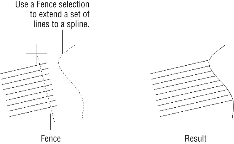
Fence [F↵] Selects objects that are crossed by a temporary line called a fence. This operation is like using a line to cross out the objects you want to select. After you invoke this option, you can then pick points, as when you’re drawing a series of line segments. After you finish drawing the fence, press ↵, and then go on to select other objects or press ↵ again to finish your selection.
Group [G↵] Allows you to select a group by name.
Last [L↵] Selects the last object you created.
Multiple [M↵] Lets you select several objects first before AutoCAD highlights them. In a large file, selecting objects individually can cause AutoCAD to pause after each selection while it locates and highlights each object. The Multiple option can speed things up by letting you first select all the objects quickly and then highlight them all by pressing ↵. This has no menu equivalent.
Previous [P↵] Selects the last object or set of objects that was edited or changed.
Remove [R↵] Switches to a selection mode whereby the objects you click are removed from the selection set.
Subobject [SUm] Allows selection of faces, edges, and vertices of 3D solid objects. This can also be accomplished by pressing the Ctrl key while picking.
Object [Om] Ends selecting by Subobject and restores normal behavior.
Undo [Um] Removes the most recently added object from the selection set.
Window [W↵] Forces a standard window selection. This option is useful when your drawing area is too crowded to use the Autoselect feature to place a window around a set of objects. (See the Auto entry later in this sidebar.) It prevents you from accidentally selecting an object with a single pick when you’re placing your window.
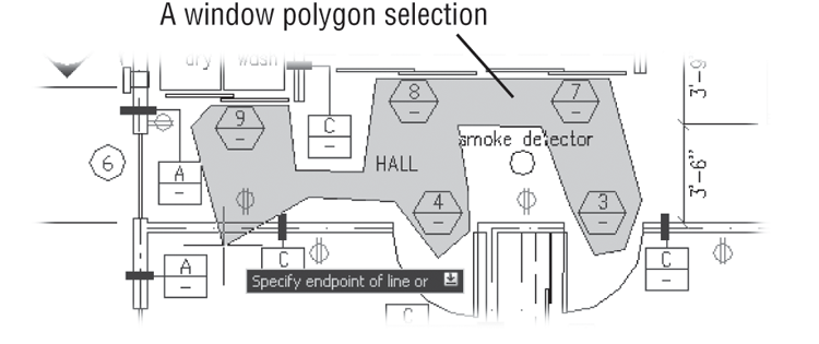
Window Polygon [WP↵] Lets you select objects by enclosing them in an irregularly shaped polygon boundary. When you use this option, you see the First polygon point: prompt. You then pick points to define the polygon boundary. As you pick points, the Specify endpoint of line or [Undo]: prompt appears. Select as many points as you need to define the boundary. You can undo boundary line segments as you go by pressing U↵. With the boundary defined, press ↵. The bounded objects are highlighted and the Select objects: prompt returns, allowing you to use more selection options.
The following two selection options are also available but are seldom used. They’re intended for use in creating custom menu options or custom tools:
Auto [AU↵] Forces the standard automatic window or crossing window when a point is picked and no object is found. (See the section “Using Autoselect” later in this chapter.) A standard window is produced when the two window corners are picked from left to right. A crossing window is produced when the two corners are picked from right to left. After this option is selected, it remains active for the duration of the current command. Auto is intended for use on systems on which the Autoselect feature has been turned off.
Single [SI↵] Forces the current command to select only a single object. If you use this option, you can pick a single object and the current command acts on that object as if you had pressed ↵ immediately after selecting it. This has no menu equivalent.
In addition to Noun/Verb selection, AutoCAD offers selection options that let you use familiar GUI techniques. See Appendix B to learn how you can control object-selection methods. This appendix also describes how to change the size of the Standard cursor.
Try moving objects by first selecting them and then using the Move command:
1. Press the Esc key twice to make sure AutoCAD isn’t in the middle of a command you might have accidentally issued. Then click the arc. The arc is highlighted, and you may also see squares appear at various points on the arc. As stated earlier, these squares are called grips. You’ll get a chance to work with them later.
2. Choose Move from the Home tab’s Modify panel. The cursor changes to Point Selection mode. Notice that the grips on the arc disappear but the arc is still selected.
3. At the
Specify base point or [Displacement] <Displacement>: prompt, pick any point on the screen. The following prompt appears:
Specify second point or
<use first point as displacement>:
4. Type @1<0↵. Metric users should type @3<0↵. The arc moves to a new location 1 unit (3 units for metric users) to the right.
If this exercise doesn’t work as described here, chances are that the Noun/Verb setting has been turned off on your copy of AutoCAD. To turn on the Noun/Verb setting, choose Options from the Application menu to open the Options dialog box and then click the Selection tab. In the Selection Modes group, place a check mark in the check box next to the Noun/Verb Selection option and click OK.
In this exercise, you picked the arc before issuing the Move command. Then, when you clicked the Move tool, you didn’t see the Select objects: prompt. Instead, AutoCAD assumed you wanted to move the arc that you selected and went directly to the Specify base point or [Displacement] <Displacement>: prompt.
Using Autoselect
Next you’ll move the rest of the door in the same direction by using the Autoselect feature:
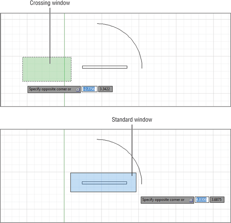
1. Pick a point just above and to the left of the rectangle representing the door. Be sure not to pick the door itself. A selection window appears that you can drag across the screen as you move the cursor. If you move the cursor to the left of the last point selected, the window outline appears dotted and there’s a green tint inside the window (see the first image in
Figure 2-21). If you move the cursor to the right of that point, the outline appears solid and there’s a blue tint inside (see the second image in
Figure 2-21).
2. Pick a point below and to the right of the door so that the door, but not the arc, is completely enclosed by the window, as shown in the bottom image in
Figure 2-21. The door is highlighted (and, again, you may see grips appear at the lines’ endpoints and midpoints).
3. Click the Move tool again. Just as in the preceding exercise, the Specify base point or [Displacement] <Displacement>: prompt appears.
4. Pick any point on the screen; then enter @1<0↵. Metric users should enter @3<0↵. The door joins with the arc.
The two selection windows you’ve just seen—the blue solid one and the dotted green one—represent a standard window and a crossing window. If you use a standard window, anything completely within the window is selected. If you use a crossing window, anything that crosses through the window is selected. These two types of windows start automatically when you click any blank portion of the drawing area with a Standard cursor or a Point Selection cursor, hence the name Autoselect.
Next, you’ll select objects with an automatic crossing window:
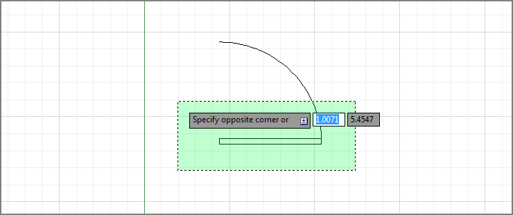
1. Pick a point below and to the right of the door. As you move the cursor left, the crossing (dotted) window appears.
2. Select the next point so that the window encloses the door and part of the arc (see
Figure 2-22). The entire door, including the arc, is highlighted.
3. Click the Move tool.
4. Pick any point on the screen; then enter @1<180↵. Metric users should type @3<180↵. The door moves back to its original location.
You’ll find that, in most cases, the Autoselect standard and crossing windows are all you need when selecting objects. They really save you time, so you’ll want to become familiar with these features.
Modifying an Autoselect Window
Two settings, known as system variables, enable you to use the Autoselect feature in a more flexible way. These two settings, Pickdrag and Pickauto, control the behavior of the Autoselect window, giving you more options to select objects in your drawing.
Pickdrag If you click to start a selection window and then decide you want to use a window polygon, crossing polygon, or fence, you can type W↵ for a window polygon, C↵ for a crossing polygon, or F↵ for a fence. If this does not work, make sure the Pickdrag system variable is set to 2 by typing PICKDRAG↵2↵.
Pickauto In a crowded drawing, you may want to use a selection window, but objects close to the cursor may be selected instead. If you set Pickauto to 2 by typingPICKAUTO↵2↵, you can click and drag your mouse over an object in a crowded drawing without having the single object selected. AutoCAD will start a selection window instead. You can still use a single click to select a single object.
Before continuing, click the Save tool in the Quick Access toolbar to save the Door.dwg file. You won’t want to save the changes you make in the next section, so saving now stores the current condition of the file on your hard disk for safekeeping.
Restrictions on Noun/Verb Object Selection
For many of the modifying or construction-oriented commands, the Noun/Verb selection method is inappropriate because, for those commands, you must select more than one set of objects. You’ll know whether a command accepts the Noun/Verb selection method right away. Commands that don’t accept the Noun/Verb selection method clear the selection and then ask you to select an object or set of objects.
If you’d like to take a break, now is a good time to do so. If you want, exit AutoCAD, and return to this point in the exercise later. When you return, start AutoCAD and open the Door.dwg file.
Editing with Grips
Earlier, when you selected the door, grips appeared at the endpoints, center points, and midpoints of the lines and arcs. You can use grips to make direct changes to the shape of objects or to move and copy them quickly.
If you didn’t see grips on the door in the previous exercise, your version of AutoCAD may have the Grips feature turned off. To turn them on, refer to the information on grips in Appendix B.
So far, you’ve seen how operations in AutoCAD have a discrete beginning and ending. For example, to draw an arc, you first issue the Arc command and then go through a series of operations, including answering prompts and picking points. When you’re finished, you have an arc and AutoCAD is ready for the next command.
The Grips feature, on the other hand, plays by a different set of rules. Grips offer a small yet powerful set of editing functions that don’t conform to the lockstep command/prompt/input routine you’ve seen so far. As you work through the following exercises, it’s helpful to think of grips as a subset of the standard method of operation in AutoCAD.
To practice using the Grips feature, you’ll make some temporary modifications to the door drawing.
Stretching Lines by Using Grips
In this exercise, you’ll stretch one corner of the door by grabbing the grip points of two lines:
1. Use the Zoom Realtime tool from the Zoom tool in the View tab’s Navigate 2D panel to adjust your view so the size of the door is similar to what is shown in
Figure 2-23. You can click and drag the mouse wheel to pan the view if needed.
2. Press the Esc key to make sure you’re not in the middle of a command. Click a point below and to the left of the door to start a selection window.
3. Click above and to the left of the rectangular part of the door, and then place the selection window around the door rectangle and click to select it.
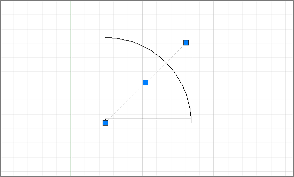
4. Place the cursor on the lower-left corner grip of the rectangle, but don’t press the mouse button yet. Notice that the cursor jumps to the grip point and that the grip is highlighted. You also see some dimensions related to the objects associated with the grip.
5. Move the cursor to another grip point. Notice again how the cursor jumps to it. When placed on a grip, the cursor moves to the exact center of the grip point. This means that, for example, if the cursor is placed on an endpoint grip, it’s on the exact endpoint of the object.
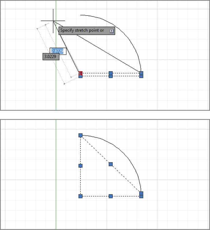
6. Move the cursor to the upper-left corner grip of the rectangle and click. The grip becomes a solid color and is now a
hot grip. The prompt displays the following message:
**STRETCH**
Specify stretch point or [Base point/Copy/Undo/eXit]:
This prompt tells you that Stretch mode is active. Notice the options in the prompt. As you move the cursor, the corner follows, and the lines of the rectangle stretch (see
Figure 2-23).
You can control the size and color of grips by using the Selection tab in the Options dialog box; see Appendix B for details.
7. Move the cursor upward toward the top end of the arc and click that point. The rectangle deforms, with the corner placed at your pick point (see
Figure 2-23).
Here you saw that a command called Stretch is issued by clicking a grip point. As you’ll see in these next steps, a handful of other hot-grip commands are also available:
1. Notice that the grips are still active. Click the grip point that you moved before to make it a hot grip again.
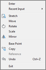
2. Right-click the mouse to open a context menu that contains a list of grip-edit options (see
Figure 2-24).
When you click the joining grip point of two contiguous line segments, AutoCAD selects the overlapping grips of two lines. When you stretch the corner away from its original location, the endpoints of both lines follow.
3. Choose Base Point from the list, and then click a point to the right of the hot grip. Now as you move the cursor, the hot grip moves relative to the cursor.
4. Right-click again, choose Copy from the context menu, and enter @1<-30↵. (Metric users should enter @3<-30↵.) Instead of the hot grip moving and the lines changing, copies of the two lines are made with their endpoints 1 unit (or 3 units for metric users) below and to the right of the first set of endpoints.
5. Pick another point just below the last. More copies are made.
6. Press ↵ or enter X↵ to exit Stretch mode. You can also right-click again and choose Exit from the context menu.
In this exercise, you saw that you can select a base point other than the hot grip. You also saw how you can specify relative coordinates to move or copy a hot grip. Finally, you saw that with grips selected on an object, right-clicking the mouse opens a context menu that contains grip edit options.
Moving and Rotating with Grips
As you’ve just seen, the Grips feature is an alternative method for editing your drawings. You’ve already seen how you can stretch endpoints, but you can do much more with grips. The next exercise demonstrates some other options. You’ll start by undoing the modifications you made in the preceding exercise:
1. Type U↵. The copies of the stretched lines disappear.
2. Press ↵ again. The deformed door snaps back to its original form.
Pressing ↵ at the Command prompt causes AutoCAD to repeat the last command entered—in this case, U.
3. You are going to select the entire door. First click a blank area below and to the right of the door.
4. Move the cursor to a location above and to the left of the rectangular portion of the door and click. Because you went from right to left, you created a crossing window. Recall that the crossing window selects anything enclosed and crossing through the window.
5. Click the lower-left grip of the rectangle to turn it into a hot grip. Just as before, as you move your cursor the corner stretches.
6. Right-click and choose Move from the context menu. The Command window displays the following:
**MOVE**
Specify move point or [Base point/Copy/Undo/eXit]
Now as you move the cursor, the entire door moves with it.
7. Position the door near the center of the screen and click. The door moves to the center of the screen. Notice that the Command prompt returns but the door remains highlighted, indicating that it’s still selected for the next operation.
8. Click the lower-left grip again, right-click, and choose Rotate from the context menu. The Command window displays the following:
**ROTATE**
Specify rotation angle or [Base point/Copy/Undo/Reference/eXit]:
As you move the cursor, the door rotates about the grip point.
9. Position the cursor so that the door rotates approximately 180° (see
Figure 2-25). Then Ctrl+click the mouse (hold down the Ctrl key and press the left mouse button). A copy of the door appears in the new rotated position, leaving the original door in place.
10. Press ↵ to exit Grip Edit mode.
You’ve seen how the Move command is duplicated in a modified way as a hot-grip command. Other hot-grip commands (Stretch, Rotate, Scale, and Mirror) have similar counterparts in the standard set of AutoCAD commands. You’ll see how those work in Chapter 12, “Using Dimensions,” and Chapter 14, “Copying Existing Drawings from Other Sources.”
After you complete any operation by using grips, the objects are still highlighted with their grips active. To clear the grip selection, press the Esc key.
In this exercise, you saw how hot-grip options appear in a context menu. Several other options are available in that menu, including Exit, Base Point, Copy, and Undo.
You can access many of these grip-edit options by pressing the spacebar or ↵ while a grip is selected. With each press, the next option becomes active. The options then repeat if you continue to press ↵. The Ctrl key acts as a shortcut to the Copy option. You have to use it only once; then, each time you click a point, a copy is made.
Scaling with Grips
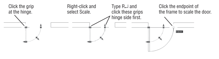
Grips can be used to scale an object graphically to fit between two other objects. For example, a door can be scaled to fit within a door frame. Place the door so that its hinge side is at the door frame and the door is oriented properly for the frame. With the door selected, click the grip at the hinge side. Right-click and select Scale. Type R↵ or select Reference from the command line, and then click the grip at the hinge again. Click the grip at the end of the arc representing the door swing. Finally, click the opposite side of the door frame.
Understanding Dynamic Input
You’ve seen how AutoCAD displays a lot of information at the cursor through its Dynamic Input display. In this section, you’ll now get a chance to explore the Dynamic Input display through grip editing.
You’ll start by going back to the original version of the Door.dwg drawing that you saved earlier:
1. Click the Close icon in the drawing tab of the drawing area.
2. When you’re asked if you want to save changes, click No.
3. Click Open from the Quick Access toolbar, and then locate and select the Door.dwg file you saved earlier. You can also open the doorsample.dwg file from the sample files you installed from this book’s web page.
The door appears in the condition in which you left it when you last saved the file.
4. Click the Pan tool in the Navigation bar and click and drag the mouse to pan the view to the center of the drawing area.
5. Right-click and select Exit to exit the Pan tool.
6. Click the arc to expose its grips.
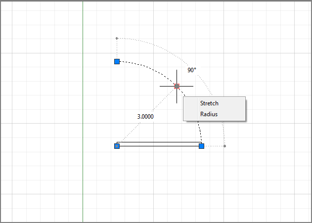
7. Place the cursor on the grip at the middle of the arc, but don’t click it. (This is called
hovering over a grip.) You see the dimensions of the arc appear as well as a menu offering two options: Stretch and Radius. The dimensions are useful when you need to check the size of objects you’ve drawn (see
Figure 2-26).
8. Click the Radius option in the grip menu. The Command prompt appears at the cursor, and the radius dimension changes to a text box.
9. Move the cursor toward the upper-right corner of the drawing area. The radius dimension of the arc changes as you move the cursor.
10. Enter 4↵. Metric users enter 12↵. As you type, the new value appears in the radius dimension. When you press ↵, the arc changes to the new radius.
11. Click the Undo button to revert to the original arc size.
Here you saw the basic methods for using the Dynamic Input display. You can hover over an object’s grip to display its dimensions along with a grip menu. The menu appears for many but not all grips, and the contents of the menu depend on the object selected. Click the grip and, if available, the dimensions can be edited directly through the keyboard. In this example, you were able to change the radius of the arc to an exact value by selecting the Radius option from the grip menu and then entering a value. Depending on the grip you click, you can change a dimension through direct keyboard input. For example, if you want to change the degrees the arc covers instead of its radius, you can hover over the arrow grip at either end of the arc and select Lengthen. The dimensions that appear can then be edited to increase or decrease the length of the arc without affecting its radius.
Next, try Dynamic Input display on a line:
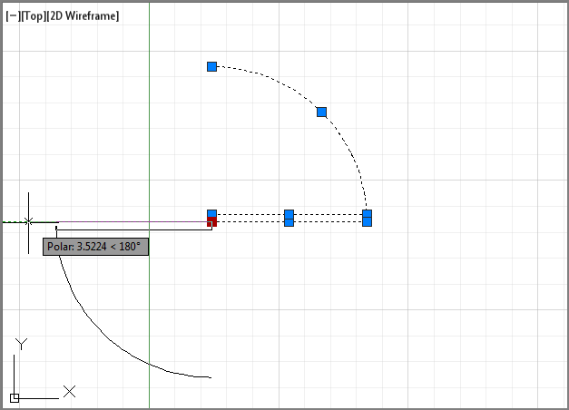
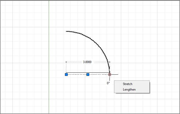
1. Click the bottommost line of the door, as shown in
Figure 2-27; hover over the rightmost grip on the selected line. Just as you saw with the arc, you can see the dimensions of the line, including its length and directional angle. You also see a menu that offers the Stretch and Lengthen option.
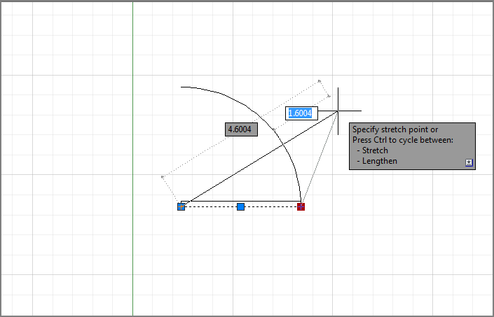
2. Click the grip over which you’re hovering, and then move the cursor up and to the right. You see two dimensions: One indicates the overall length and the other shows the change in length of the line. You also see the Command prompt at the cursor. Notice that the dimension indicating the change in length is highlighted (see
Figure 2-28).
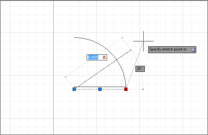
3. Type
1 and press the Tab key, not the return key, to increase the length of the line by 1 unit. Metric users should enter
30 and press the Tab key. Now, as you move the cursor, the line is locked at a new length that is 1 or 30 units longer than its original length. Also notice that the overall dimension is highlighted. You also see a lock icon on the length dimension (see
Figure 2-29).
4. Press the Tab key again. The angle value is highlighted.
5. Type 45 and press the Tab key to lock the angle of the line at 45°.
6. Make sure the cursor isn’t too close to the locked endpoint of the line and then click the left mouse button. The line is now in its new orientation with a length of 4 (130 for metric users) and an angle of 45°, as shown in
Figure 2-30.
You can see that the Dynamic Input display lets you enter specific dimensions for the selected object, making possible precise changes in an object’s size. You can also choose Lengthen from the grip menu if you just want to change the length of the line.
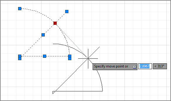
You can also use the Dynamic Input display while using other grip-editing features. Try the following exercise to see how the Dynamic Input display works while moving objects:
1. Click above and to the right of the door drawing to start a crossing selection window.
2. Click below and to the left to select the entire door drawing.
3. Click the middle grip of the arc.
4. Right-click and choose Move. You see the Command prompt at the cursor with the distance value highlighted. As you move the cursor, you can see the distance and angle values in the Dynamic Input display change (see
Figure 2-31).
5. Type 4 and then press the Tab key. As you move the cursor, the distance from the original location of the arc’s midpoint is locked at 4 (or 130) units. The angle value is now highlighted and available for editing.
6. Type 225 and then press the Tab key to lock the angle at 225°.
7. Click a location away from the door drawing. The door moves to its new location, exactly 4 units from its original location.
As you can see from these exercises, the Dynamic Input display adds some helpful methods for editing objects. To summarize, here is a rundown of the basic Dynamic Input display features:
- You can quickly check the dimensions of an object by selecting it and then hovering over a grip.
- You can alter an object’s dimensions by entering values into the highlighted dimensions of the Dynamic Input display.
- To highlight a different dimension, press the Tab key.
- To accept any changes you’ve made using the Dynamic Input display, click the mouse at a location away from the grip you’re editing. You can also press ↵ or the spacebar.
Not all grips offer dimensions that can be edited. If you click the midpoint grip on the line, for example, you won’t see the dimensions of the line, although you’ll see the Command prompt and you’ll be able to enter a new coordinate for the midpoint.
As you’ve seen in the arc and line examples, each object offers a different set of dimensions. If you like the way the Dynamic Input display works, you can experiment on other types of objects. AutoCAD offers a number of settings that let you control the behavior of the Dynamic Input display. You’ll learn about those settings in Appendix B.
Typing Coordinates with Dynamic Input
When entering coordinates through the keyboard while Dynamic Input is enabled, you have to use a slightly different notation for relative and absolute coordinates. If you’re entering relative coordinates, you can leave off the @ sign, so instead of typing @12,9↵, you can simply type 12,9↵. If you are entering absolute coordinates, you need to precede your coordinate list with a # sign. So instead of entering 1,1↵ to specify a point at coordinate 1,1, you would need to enter #1,1↵.
Displaying Data in a Text Window
You may have noticed that as you work in AutoCAD, the activity displayed in the Command window scrolls up. Sometimes, it’s helpful to view information that has scrolled past the view shown in the Command window. For example, you can review the command activity from your session to check input values or to recall other data-entry information. Try the following exercise to see how the Text Window works:
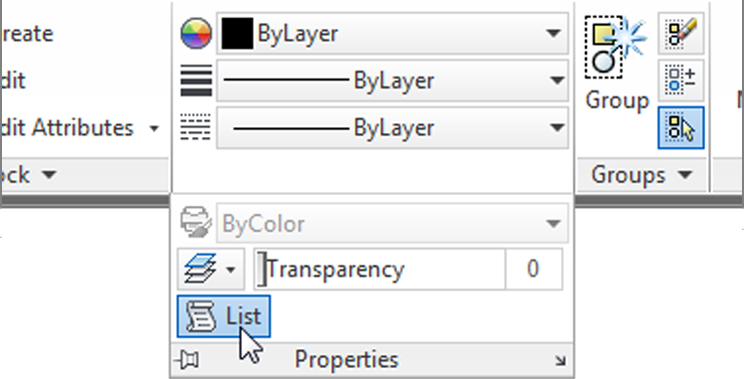
1. From the Home tab’s expanded Properties panel, click the List tool.
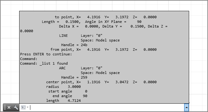
2. At the
Select objects: prompt, click the arc and press ↵. The Command window expands to display information about the arc (see
Figure 2-32). Toward the bottom is the list of the arc’s properties. Don’t worry if the meaning of some listed properties isn’t obvious yet; as you work your way through this book, you’ll learn what the properties of an object mean.
3. You can dismiss the expanded Command window by clicking in the drawing area. To bring it back, press the F2 function key or click the upward pointing arrowhead at the far right of the Command window.
You can set the number of lines that AutoCAD retains by using the Options dialog box, or you can have AutoCAD record the AutoCAD Text Window information in a text file.
When you have more than one document open, the AutoCAD Command window displays a listing for the drawing that is currently active.
Docking the Command Window
If you’ve used AutoCAD before, you may wonder if you can restore the old-style Command window. You can do this by docking the window to the bottom of the AutoCAD window. Once this is done, the Command window behaves the same way as in earlier versions of AutoCAD. You can open a separate Text Window by entering TEXTS↵.
Displaying the Properties of an Object
While we’re on the subject of displaying information, you’ll want to know about the Properties palette. In the preceding exercise, you saw how the List command showed some information regarding the properties of an object, such as the location of an arc’s center and endpoints. You can also double-click an object to display the Quick Properties palette that shows other basic information about the object. (You might accidentally display the Quick Properties palette from time to time!) The Properties palette provides a more complete view of an object’s properties with the additional feature of allowing you to make changes to those properties. The Properties palette is so useful, you may want to consider leaving it open all the time.
To see what the Properties palette is for, try the following exercise:
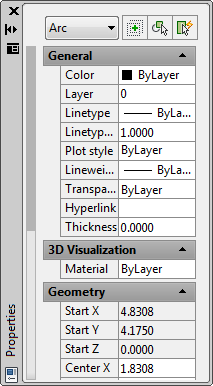
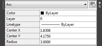
1. If you haven’t done so already, select the arc in the drawing, right-click it, and select Properties to open the Properties palette, which displays a list of the arc’s properties. Don’t worry if many of the items in this palette are undecipherable; you’ll learn more about this palette as you work through the early chapters of this book. For now, just be aware that you can get to this palette with a right-click and that it displays the object’s properties. You can also use it to modify many of the properties listed (see
Figure 2-33).
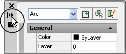
2. Click the small Auto-hide box at the top of the Properties palette. It’s the icon that looks like a double arrow. The icon changes to a single arrow. The Auto-hide option in the Properties palette lets you keep the palette open without having it take up too much of the drawing area. This can be useful when you need to edit the properties of many objects.
3. Move the cursor away from the Properties palette. The Properties palette collapses so that only the title bar remains.
4. Hover the cursor on the Properties palette title bar. The Properties palette opens to display all the options again.
5. Click the Auto-hide box again to restore the “always open” mode of the palette.
6. Close the Properties palette by clicking the X in its upper corner. (The X appears in the upper-left or upper-right corner, depending on the placement of the palette in the AutoCAD window.) You can also right-click the title bar on the side of the Properties palette and then choose Close from the context menu.
7. You’re finished with the door drawing, so choose Close from the Application menu.
8. In the AutoCAD dialog box, click the No button. (You’ve already saved this file just as you want it, so you don’t need to save it again.)
In many cases, you can open the Properties palette by double-clicking an object. Some objects, however, display a dialog box to allow you to edit them.
Another feature related to the Properties palette is the Quick Properties tool and palette. If you turn on Quick Properties by clicking the Quick Properties tool in the status bar, you’ll see the Quick Properties palette whenever you select an object or set of objects (Figure 2-34).
The Quick Properties palette lets you control just a few properties of an object (color, layer, and linetype). When turned on, it pops up every time you select an object, so you may want to limit its use to those times when you are adjusting the color, layer, and linetype of objects in your drawing.
Using Rotate Reference to Align Objects
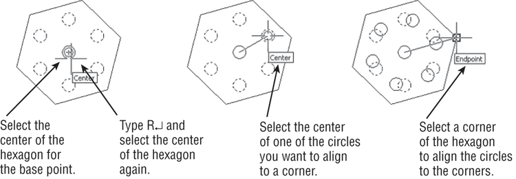
You can use the Rotate command’s Reference option to align a set of objects graphically to another object. For example, suppose you want to rotate a set of circles inside a hexagon to align with the corner of the hexagon.
To do this, you can use the Reference option as follows:
1. Start the Rotate command, and select the circles.
2. At the Specify base point: prompt, use the Center osnap to select the center of the hexagon as represented by the central circle. Once you do this, the objects rotate around the selected point as you move your cursor.
3. At the Specify rotation angle or [Copy/Reference]: prompt, enter R↵.
4. At the Specify the reference angle <0>: prompt, use the Center osnap to select the center of the hexagon again. You can also enter @↵ since the last point you selected was the center.
5. At the Specify second point: prompt, use the Center osnap to select the center of one of the circles you want to align with the hexagon. Now, as you move the cursor, the circle whose center you selected is aligned with the cursor angle.
6. At the Specify the new angle or [Points]: prompt, use the Endpoint osnap to select one of the corners of the hexagon. The circles align with the corners.
You can also use grips to align objects. Here’s how: Select the object or set of objects and then click a grip. The grip you select becomes the rotation point, so select this first grip carefully. Right-click and select Rotate. Type R↵ and select the grip you just selected and another point to determine the reference angle. Finally, select the new angle for the object or set of objects. If you want to rotate about a point other than the first grip, use the Grip Base right-click option.
Getting Help
Eventually, you’ll find yourself somewhere without documentation and you’ll have a question about an AutoCAD feature. AutoCAD provides an online help facility that gives you information on nearly any topic related to AutoCAD. Here’s how to find help:
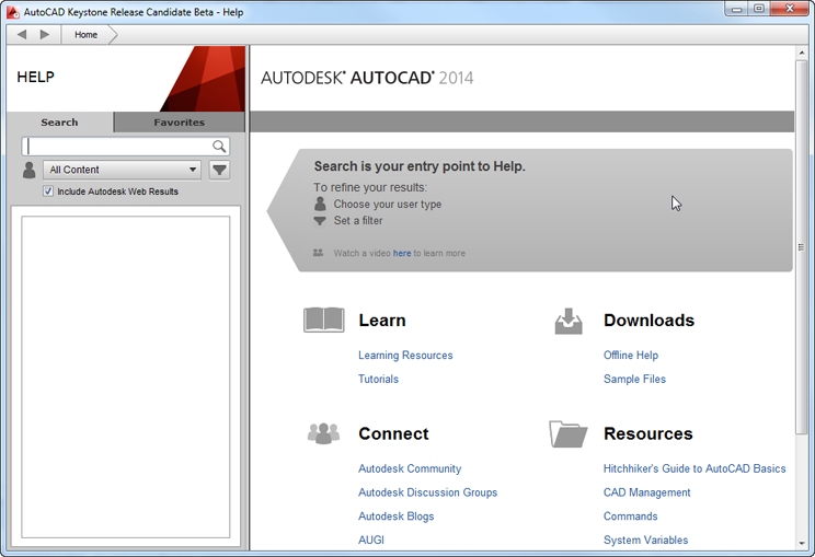
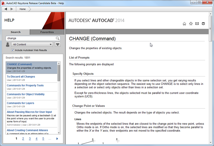
1. Click the Help tool from the InfoCenter to open the AutoCAD Help window (see
Figure 2-35).
2. Take a moment to see what is offered in this window. On the left is a column dedicated to the search function for the site. The panel on the right contains several links to a variety of topics. At the very top, you’ll see a forward and a backward arrow and a home button.
3. Click Learning Resources from the Learning panel under QuickLinks; then click 2014 under AutoCAD Help on the AutoCAD Service & Support page.
4. Click Commands, and the page changes to show the Command Quick Reference page.
5. Click M in the list of letters. You’ll see a list of command names that start with M.
You also have the Search and Favorites tab in the left column. The Search tab is currently selected. Enter a question in the search input box and the space below the input box fills with links to search results. Click on a link and detailed information appears in the right panel. At the top of the right panel, you can click the Add To Favorites icon to save the link under Favorites.
Using the InfoCenter
If you want to find information about a topic based on a keyword, you can use the InfoCenter in the upper-right corner of the AutoCAD window. Follow these steps:
1. Type change in the InfoCenter text box at the top right of the AutoCAD window, and then click the Search tool to the right of the input box.
2. The AutoCAD Help window opens and displays information on the Change command (see
Figure 2-36).
You can use Boolean AND, OR, NEAR, and NOT in conjunction with other keywords to help filter your searches, just as in a typical search engine that you might use in your web browser.
Exploring the AutoCAD 2014 Welcome Screen
You’ve probably noticed the AutoCAD 2014 Welcome Screen when AutoCAD starts up and were wondering what it offers. The Welcome Screen (see Figure 2-37) connects you with resources that can enhance your AutoCAD experience.
The Welcome Screen offers links to videos and tutorials that will help you learn about the new features in AutoCAD 2014. If you have a problem with AutoCAD, you can click the Online Resources link, which opens the AutoCAD Service & Support website. Autodesk Exchange is a website that offers plug-ins to AutoCAD, many of which are free. Autodesk 360 is a site that enables you to store and share documents.
You will need to create an account for Autodesk Exchange and Autodesk 360. You can do so by using the Sign In text box just to the right of the search text box in the AutoCAD InfoCenter.
Finding Additional Sources of Help
The InfoCenter is the main online source for reference material, but you can also find answers to your questions through the other options in the InfoCenter’s Help flyout menu. You can open this menu by clicking the arrowhead next to the InfoCenter Help tool. Here is a brief description of them:
Help Opens the AutoCAD 2014 Help website.
Download Offline Help Lets you select and download help files that can be stored locally on your PC. These help files can be useful if you find yourself in a location without Internet access.
Welcome Screen If you close the Welcome Screen when you start AutoCAD or if you choose to not have the Welcome Screen open at startup, you can bring it back with this option.
Send Feedback Autodesk offers the product feedback web page, which enables you to send comments to Autodesk. The Send Feedback option takes you directly to this page.
Download Language Packs If you need to set up AutoCAD for a language other than English, you can download a language pack using this link.
Customer Involvement Program The Customer Involvement Program is really a way for Autodesk to monitor the condition of AutoCAD by allowing its customers to send comments about program errors or crashes. This voluntary program lets you participate anonymously, or you can provide contact information for follow-up contacts.
About This option provides information about the version of AutoCAD you’re using.
The Bottom Line
Specify distances with coordinates. One of the most basic skills you need to learn is how to indicate exact distances through the keyboard. AutoCAD uses a simple annotation system to indicate distance and direction.
Master It What would you type to indicate a relative distance of 14 units at a 45° angle?
Interpret the cursor modes and understand prompts. The AutoCAD cursor changes its shape depending on the command that is currently active. These different cursor modes can give you a clue regarding what you should be doing.
Master It Describe the Point Selection cursor and the Pickbox cursor.
Select objects and edit with grips. Grips are small squares or arrowheads that appear at key points on the object when they’re selected. They offer a powerful way to edit objects.
Master It How do you select multiple grips?
Use dynamic input. Besides grips, objects display their dimensional properties when selected. These dimensional properties can be edited to change an object’s shape.
Master It How do you turn on the Dynamic Input display? And once it’s on, what key lets you shift between the different dimensions of an object?
Display data in a text window. AutoCAD offers the AutoCAD Text Window, which keeps a running account of the commands you use. This can be helpful in retrieving input that you’ve entered when constructing your drawing.
Master It Name a command that displays its results in the AutoCAD Text Window.
Display the properties of an object. The Properties palette is one of the most useful sources for drawing information. Not only does it list the properties of an object, it lets you change the shape, color, and other properties of objects.
Master It How do you open the Properties palette for a particular object?
Get help. The AutoCAD Autodesk Exchange website is thorough in its coverage of AutoCAD features. New and experienced users alike can often find answers to their questions through the Help window, so it pays to become familiar with it.
Master It What keyboard key do you press for context-sensitive help?