
Chapter 4
Organizing Objects with Blocks and Groups
Drawing the tub, toilet, and sink in Chapter 3, “Setting Up and Using the Drafting Tools,” may have taken what seemed to you an inordinate amount of time. As you continue to use the AutoCAD® 2014 software, however, you’ll learn to draw objects more quickly. You’ll also need to draw fewer of them because you can save drawings as symbols and then use those symbols like rubber stamps, duplicating drawings instantaneously wherever they’re needed. This saves a lot of time when you’re composing drawings.
To make effective use of AutoCAD, begin a symbol library of drawings you use frequently. A mechanical designer might have a library of symbols for fasteners, cams, valves, or even complete assemblies used in their application. An electrical engineer might have a symbol library of capacitors, resistors, switches, and the like. A circuit designer will have yet another unique set of frequently used symbols.
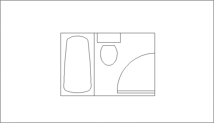
In Chapter 3, you drew three objects that architects often use—a bathtub, a toilet, and a sink. In this chapter, you’ll see how to create symbols from those drawings.
In this chapter, you will learn to:
- Create and insert a symbol
- Modify a block
- Understand the annotation scale
- Group objects
Creating and Using a Symbol
To save a drawing as a symbol, you use the tools in the Home tab’s Block panel or the Insert tab’s Block Definition panel. In word processors, the term block refers to a group of words or sentences selected for moving, saving, or deleting. You can copy a block of text elsewhere within the same file, to other files, or to a separate location on a server or USB storage device for future use. AutoCAD uses blocks in a similar fashion. In a file, you can turn parts of your drawing into blocks that can be saved and recalled at any time. You can also use entire existing files as blocks.
You’ll start by opening the file you worked on in the previous chapter and selecting the objects that will become a block:
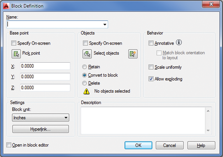
Figure 4-1 The Block Definition dialog box
When you turn an object into a block, it’s stored in the drawing file, ready to be recalled at any time. The block remains part of the drawing file even when you end the editing session. When you open the file again, the block is available for your use. In addition, you can access blocks from other drawings by using the AutoCAD DesignCenter™ and the tool palettes. You’ll learn more about the DesignCenter and the tool palettes in Chapter 27, “Managing and Sharing Your Drawings.”
A block acts like a single object, even though it’s made up of several objects. One unique characteristic of a block is that when you modify it, all instances of it are updated to reflect the modifications. For example, if you insert several copies of the toilet into a drawing and then later decide the toilet needs to be a different shape, you can edit the Toilet block, and all the other copies of the toilet are updated automatically.
You can modify a block in a number of ways after it has been created. In this chapter, you’ll learn how to make simple changes to individual blocks by modifying the block’s properties. For more detailed changes, you’ll learn how to redefine a block after it has been created. Later, in Chapter 18, “Using Dynamic Blocks,” you’ll learn how to use the Block Editor to make more interactive blocks.
Understanding the Block Definition Dialog Box
The Block Definition dialog box offers several options that can help make using blocks easier. If you’re interested in these options, take a moment to review the Block Definition dialog box as you read the descriptions. If you prefer, you can continue with the tutorial and come back to this section later.
You’ve already seen how the Name option lets you enter a name for your block. AutoCAD doesn’t let you complete the block creation until you enter a name.
You’ve also seen how to select a base point for your block. The base point is like the grip of the block: It’s the reference point you use when you insert the block back into the drawing. In the exercise, you used the Pick Point option to indicate a base point, but you also have the option to enter x-, y-, and z-coordinates just below the Pick Point option. In most cases, however, you’ll want to use the Pick Point option to indicate a base point that is on or near the set of objects you’re converting to a block.
The Objects group of the Block Definition dialog box lets you select the objects that make up the block. You use the Select Objects button to visually select the objects you want to include in the block you’re creating. The QuickSelect button to the right of the Select Objects button lets you filter out objects based on their properties. You’ll learn more about QuickSelect in Chapter 15, “Advanced Editing and Organizing.” Once you select a set of objects for your block, you’ll see a thumbnail preview of the block’s contents near the top center of the Block Definition dialog box.
Other options in the Objects group and Settings group let you specify what to do with the objects you’re selecting for your block. Table 4-1 shows a list of those other options and what they mean.
Table 4-1: The Block Definition dialog box options
| Option | Purpose | |
| Base Point group | ||
| Specify On-Screen | Lets you select the base point for the block after you click OK. | |
| Pick Point | Lets you select the base point for the block before you click OK to dismiss the dialog box. | |
| X, Y, and Z input boxes | Enables you to enter exact coordinates for the block’s base point. | |
| Objects group | ||
| Specify On-Screen | Lets you select the objects for the block after you click OK. | |
| Select Objects/QuickSelect | Lets you select the objects for the block before you click OK to dismiss the dialog box. | |
| Retain | Keeps the objects you select for your block as they are, or unchanged. | |
| Convert To Block | Converts the objects you select into the block you’re defining. The block then acts like a single object after you’ve completed the Create Block command. | |
| Delete | Deletes the objects you selected for your block. You may also notice that a warning message appears at the bottom of the Objects group. This warning appears if you haven’t selected objects for the block. After you’ve selected objects, the warning changes to tell you how many objects you’ve selected. | |
| Behavior group | ||
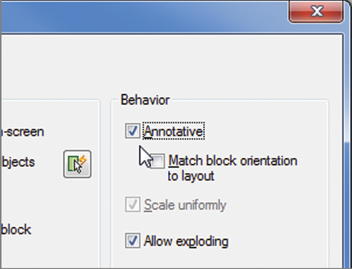
| Annotative | Turns on the Annotation scale feature for blocks. This feature lets you use a single block for different scale views of a drawing. With this feature turned on, AutoCAD can be set to adjust the size of the block to the appropriate scale for the viewport. | |
| Match Block Orientation To Layout | With the Annotative option turned on, this option is available. This option causes a block to appear always in its normal orientation regardless of the orientation of the layout view. | |
| Scale Uniformly | By default, blocks can have a different X, Y, or Z scale. This means they can be stretched in any of the axes. You can lock the X, Y, and Z scales of the block by selecting this option. That way, the block will always be scaled uniformly and can’t be stretched in one axis. | |
| Allow Exploding | By default, blocks can be exploded or reduced to their component objects. You can lock a block so that it can’t be exploded by turning off this option. You can always turn on this option later through the Properties palette if you decide that you need to explode a block. | |
| Settings group | ||
| Block Unit | Lets you determine how the object is to be scaled when it’s inserted into the drawing using the DesignCenter feature discussed in Chapter 27. By default, this value is the same as the current drawing’s insert value. | |
| Hyperlink | Lets you assign a hyperlink to a block. This option opens the Insert Hyperlink dialog box, where you can select a location or file for the hyperlink. | |
| Description and Open In Block Editor | ||
| Description | Lets you include a brief description or keyword for the block. This option is helpful when you need to find a specific block in a set of drawings. You’ll learn more about searching for blocks later in this chapter and in Chapter 27. | |
| Open In Block Editor | If you turn on this option, the block is created and then opened in the Block Editor, described in Chapter 18. | |
Inserting a Symbol
You can recall the Tub and Toilet blocks at any time, as many times as you want. You’ll draw the interior walls of the bathroom first, and then you’ll insert the tub and toilet. Follow these steps to draw the walls:
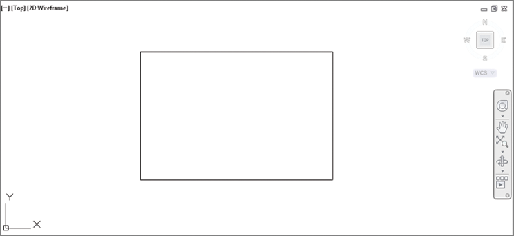
If you use the Rectangle tool to draw the rectangle, make sure you explode it by using the Explode command. This is important for later exercises. (See the section “Unblocking and Redefining a Block” later in this chapter if you aren’t familiar with the Explode command.) Your drawing should look like Figure 4-2.
Figure 4-2 The interior walls of the bathroom
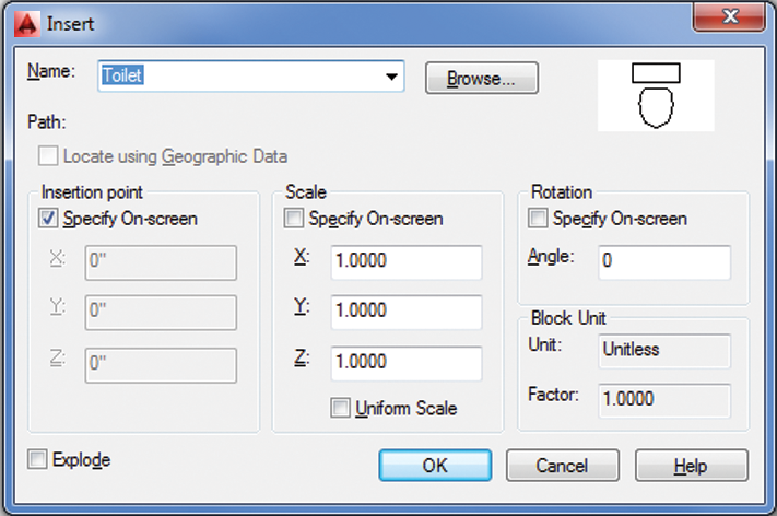
Now you’re ready to place your blocks. Start by placing the tub in the drawing. You’ll use a dialog box to do this, so you become familiar with some of the options available:
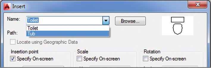
Figure 4-3 The Insert dialog box
You’ve got the tub in place. Now place the Toilet block in the drawing:
You’ve just used two methods for inserting a block. When you used the Insert dialog box to place the Tub block, you saw a number of options you could use to fine-tune the block while you insert it.
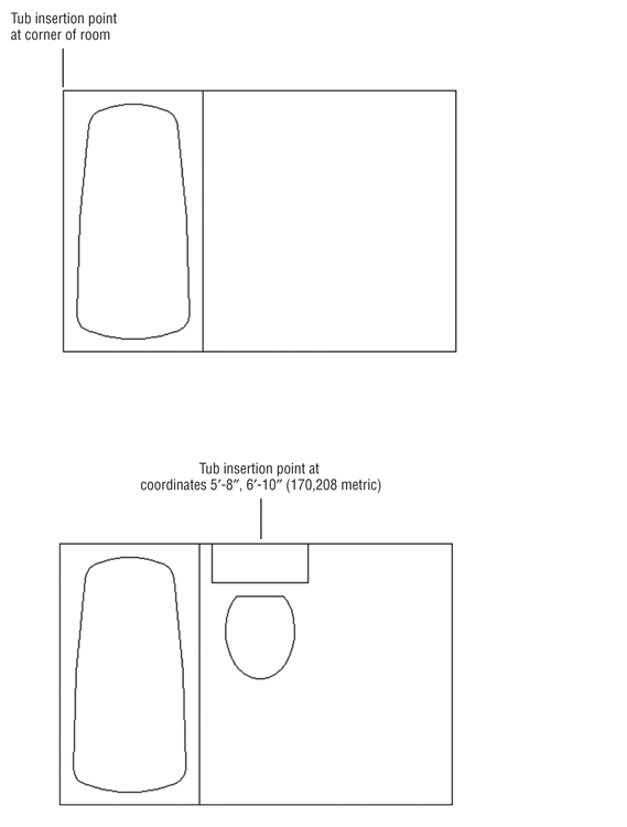
Figure 4-4 The bathroom, first with the tub and then with the toilet inserted
Scaling and Rotating Blocks
When you insert the tub, you can see it rotate as you move the cursor. You can pick a point to fix the block in place, or you can enter a rotation value. This is the result of selecting the Specify On-Screen option in the Insert dialog box. You may find that you want the Rotation group’s Specify On-Screen option turned on most of the time to enable you to adjust the rotation angle of the block while you’re placing it in the drawing.
The options in the Insert dialog box that you didn’t use are the Scale group options. These options let you scale the block to a different size. You can scale the block uniformly, or you can distort the block by individually changing its X, Y, or Z scale factor. With the Specify On-Screen option unchecked, you can enter specific values in the X, Y, and Z text boxes to stretch the block in any direction. If you turn on the Specify On-Screen option, you can visually adjust the X, Y, and Z scale factors in real time. Although these options aren’t used often, they can be useful in special situations when a block needs to be stretched one way or another to fit in a drawing.
You aren’t limited to scaling or rotating a block when it’s being inserted into a drawing. You can always use the Scale or Rotate tool or modify an inserted block’s properties to stretch it in one direction or another. The next exercise shows you how this is done:
If a block is created with the Scale Uniformly option turned on in the Block Definition dialog box, you can’t scale the block in just one axis as shown in the previous exercise. You can only scale the block uniformly in all axes.
You’ve just seen how you can modify the properties of a block by using the Properties palette. In the exercise, you changed the X scale of the Toilet block, but you could have just as easily changed the Y value. You may have noticed other properties available in the Properties palette. You’ll learn more about those properties as you work through this chapter.
You’ve seen how you can turn a drawing into a symbol, known as a block in AutoCAD. Now let’s see how you can use an existing drawing file as a symbol.
Using an Existing Drawing as a Symbol
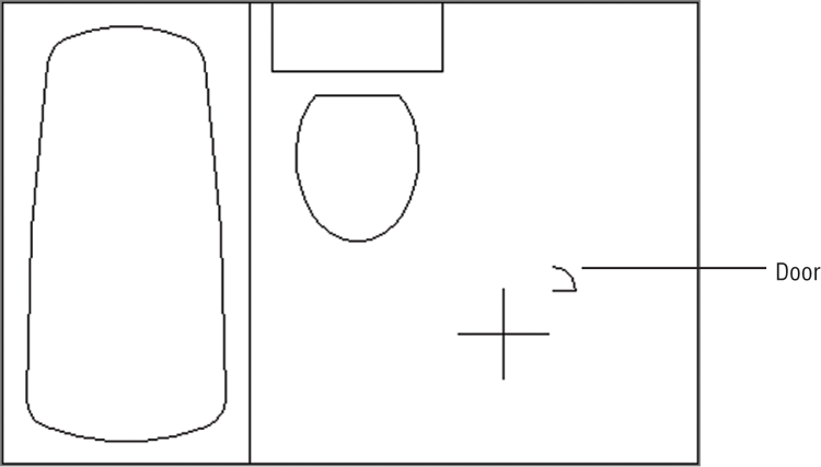
You need a door into the bathroom. Because you’ve already drawn a door and saved it as a file, you can bring the door into this drawing file and use it as a block:
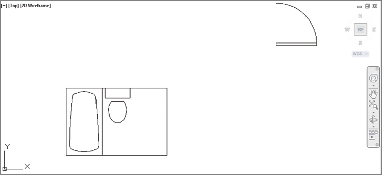
Figure 4-5 The door drawing being inserted in the Bath file
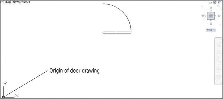
The Command prompt appears, but nothing seems to happen to the drawing. This is because when you enlarged the door, you also enlarged the distance between the base point and the object. This brings up another issue that you need to be aware of when you’re considering using drawings as symbols: All drawings have base points. The default base point is the absolute coordinate 0,0, otherwise known as the origin, which is located in the lower-left corner of any new drawing. When you drew the door in Chapter 2, you didn’t specify the base point. When you try to bring the door into this drawing, AutoCAD uses the origin of the door drawing as its base point (see Figure 4-6).
Figure 4-6 By default, a drawing’s origin is also its insertion point. You can change a drawing’s insertion point by using the Base command.
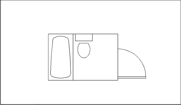
Because the door appears outside the bathroom, you must first choose All from the Zoom flyout on the View tab’s Navigate2D panel to show more of the drawing, and then use the Move command on the Modify panel to move the door to the right-side wall of the bathroom. Let’s do so now:
Figure 4-7 The enlarged door
Because the door is an object that you’ll use often, it should be a common size so you don’t have to specify an odd value every time you insert it. It would also be helpful if the door’s insertion base point were in a more convenient location—that is, a location that would let you place the door accurately within a wall opening. Next, you’ll modify the Door block better to suit your needs.
Figure 4-8 The door on the right-side wall of the bathroom
Modifying a Block
You can modify a block in three ways. One way is to redefine it completely. In earlier versions of AutoCAD, this was the only way to make changes to a block. A second way is to use the Block Editor. A third way is to use the Edit Reference tool on the Insert tab’s expanded Reference panel. The Edit Reference tool is also known as the Refedit command.
In the following sections, you’ll learn how to redefine a block by making changes to the door symbol. Later, in Chapter 18, you’ll see how the Block Editor lets you add adjustability to blocks, and in Chapter 7, “Mastering Viewing Tools, Hatches, and External References,” you’ll learn about the Edit Reference tool.
Double-clicking most objects displays the Quick Properties palette. Double-clicking a block opens the Edit Block Definition dialog box, which gives you another way to edit blocks. You’ll learn more about the Edit Block Definition dialog box in Chapter 18.
Unblocking and Redefining a Block
One way to modify a block is to break it down into its components, edit them, and then turn them back into a block. This is called redefining a block. If you redefine a block that has been inserted in a drawing, each occurrence of that block in the current file changes to reflect the new block definition. You can use this block-redefinition feature to make rapid changes to a design.
To separate a block into its components, use the Explode command:
Now you can edit the individual objects that make up the door, if you desire. In this case, you want to change only the door’s insertion point because you’ve already made it a more convenient size. You’ll turn the door back into a block, this time using the door’s lower-left corner for its insertion base point:
The Select Objects and Pick Point buttons appear in other dialog boxes. Make note of their appearance and remember that when you select them, the dialog box temporarily closes to let you select points or objects and otherwise perform operations that require a clear view of the drawing area.
In step 7, you received a warning message that you were about to redefine the existing Door block. But originally you inserted the door as a file, not as a block. Whenever you insert a drawing file by using the Insert Block tool, the inserted drawing automatically becomes a block in the current drawing. When you redefine a block, however, you don’t affect the drawing file you imported. AutoCAD changes only the block in the current file.
You’ve just redefined the door block. Now place the door in the wall of the room:
Your drawing will look like Figure 4-9.
Figure 4-9 The bathroom floor plan thus far
Next, you’ll see how you can update an external file with a redefined block.
Saving a Block as a Drawing File
You’ve seen that, with little effort, you can create a symbol and place it anywhere in a file. Suppose you want to use this symbol in other files. When you create a block by using the Block command, the block exists in the current file only until you specifically instruct AutoCAD to save it as a separate drawing file. When you have an existing drawing that has been brought in and modified, such as the door, the drawing file associated with that door isn’t automatically updated. To update the Door file, you must take an extra step and use the Export option on the Application menu. Let’s see how this works.
Start by turning the Tub and Toilet blocks into individual files:
Replacing Existing Files with Blocks
The Wblock command does the same thing as choosing Export ⇒ Other Formats, but output is limited to AutoCAD DWG files. Let’s try using the Wblock command this time to save the Door block you modified:
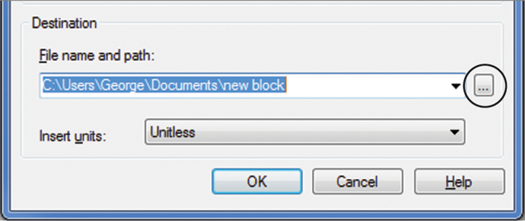
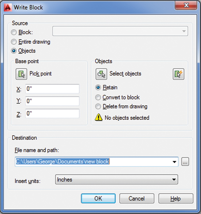
Figure 4-10 The Write Block dialog box
In this exercise, you typed the Wblock command at the Command prompt instead of choosing Export ⇒ Other Formats. The results are the same regardless of which method you use. If you’re in a hurry, the Export ⇒ Other Formats command is a quick way to save part of your drawing as a file. The Wblock option might be easier for new users because it offers options in a dialog box.
Understanding the Write Block Dialog Box Options
The Write Block dialog box offers a way to save parts of your current drawing as a file. As you can see from the dialog box shown in the previous exercise, you have several options.
In that exercise, you used the Block option of the Source group to select an existing block as the source object to be exported. You can also export a set of objects by choosing the Objects option. If you choose this option, the Base Point and Objects groups become available. These options work the same way as their counterparts in the Block Definition dialog box, which you saw earlier when you created the Tub and Toilet blocks.
The other option in the Source group, Entire Drawing, lets you export the whole drawing to its own file. This may seem to duplicate the Save As option in the Application menu, but saving the entire drawing from the Write Block dialog box performs some additional operations, such as stripping out unused blocks or other unused components. This has the effect of reducing file size. You’ll learn more about this feature later in this chapter.
Other Uses for Blocks
So far you’ve used the Block tool to create symbols, and you’ve used the Export and Wblock commands to save those symbols to disk. As you can see, you can create symbols and save them at any time while you’re drawing. You’ve made the tub and toilet symbols into drawing files that you can see when you check the contents of your current folder.
However, creating symbols isn’t the only use for the Block, Export, and Wblock commands. You can use them in any situation that requires grouping objects (though you may prefer to use the more flexible Object Grouping dialog box discussed later in this chapter). You can also use blocks to stretch a set of objects along one axis by using the Properties palette. Export and Wblock also enable you to save a part of a drawing to disk. You’ll see instances of these other uses of the Block, Export, and Wblock commands throughout the book.
Block, Export, and Wblock are extremely versatile commands and, if used judiciously, can boost your productivity and simplify your work. If you aren’t careful, however, you can get carried away and create more blocks than you can track. Planning your drawings helps you determine which elements will work best as blocks and recognize situations in which other methods of organization are more suitable.
Another way of using symbols is to use the external reference capabilities. External reference files, known as Xrefs, are files inserted into a drawing in a way similar to how blocks are inserted. The difference is that Xrefs don’t become part of the drawing’s database. Instead, they’re loaded along with the current file at startup time. It’s as if AutoCAD opens several drawings at once: the main file you specify when you start AutoCAD and the Xrefs associated with the main file.
By keeping the Xrefs independent from the current file, you make sure that any changes made to the Xrefs automatically appear in the current file. You don’t have to update each inserted copy of an Xref. For example, if you use the Attach tool on the Insert tab’s Reference panel (discussed in Chapter 7) to insert the tub drawing and later you make changes to the tub, the next time you open the Bath file, you’ll see the new version of the tub. Or if you have both the tub and the referencing drawing open and you change the tub, AutoCAD will notify you that a change has been made to an external reference. You can then update the tub Xref using the External Reference palette.
Xrefs are especially useful in workgroup environments where several people are working on the same project. One person might be updating several files that have been inserted into a variety of other files. Before Xrefs were available, everyone in the workgroup had to be notified of the changes and had to update all the affected blocks in all the drawings that contained them. With Xrefs, the updating is automatic. Many other features are unique to these files. They’re discussed in more detail in Chapter 7 and Chapter 15.
Understanding the Annotation Scale
One common use for the AutoCAD block feature is creating reference symbols. These are symbols that refer the viewer to other drawings or views in a set of drawings. An example would be a building-section symbol on a floor plan that directs the viewer to look at a location on another sheet to see a cross-section view of a building. Such a symbol is typically a circle with two numbers: one is the drawing sheet number and the other is the view number on the sheet (examples appear a little later, in Figure 4-15).
In the past, AutoCAD users had to insert a reference symbol block multiple times to accommodate different scales of the same view. For example, the same floor plan might be used for a ¼″ = 1′-0″ scale view and a 1⁄8″ = 1′-0″ view. An elevation symbol block that works for the ¼ ″ = 1′-0″ scale view would be too small for the 1⁄8″ = 1′-0″ view, so two copies of the same block were inserted, one for each scale. The user then had to place the two blocks on different layers to control their visibility. In addition, if sheet numbers changed, the user had to make sure every copy of the elevation symbol block was updated to reflect the change.
The annotation scale feature does away with this need for redundancy. You can now use a single instance of a block even if it must be displayed in different scale views. To do this, you must take some additional steps when creating and inserting the block. Here’s how you do it:
Figure 4-11 Select the Annotative option in the Block Definition dialog box.
After you’ve followed these steps, you need to apply an annotation scale to the newly created block:
Figure 4-12 The Annotation Object Scale dialog box
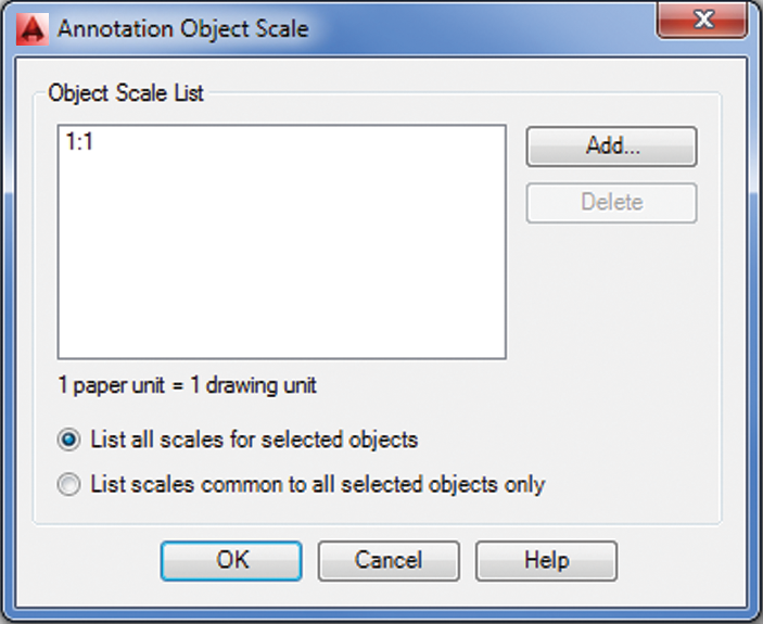
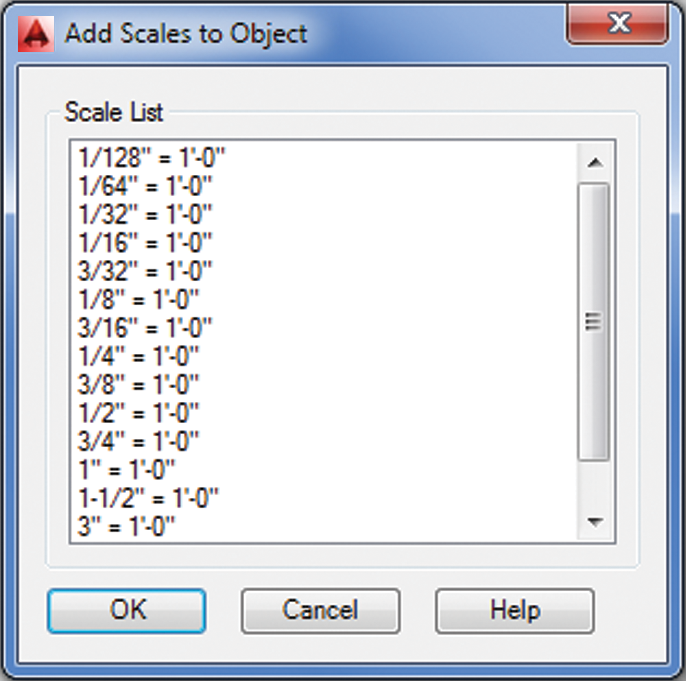
Figure 4-13 The Add Scales To Object dialog box
At this point, the block is ready to be used in multiple scale views. You need only to select a scale from the model view’s Annotation Scale drop-down list or the layout view’s Viewport Scale drop-down list, which are both in the lower-right corner of the AutoCAD window (see Figure 4-14). For you to select a scale while in a layout, a viewport border needs to be selected.
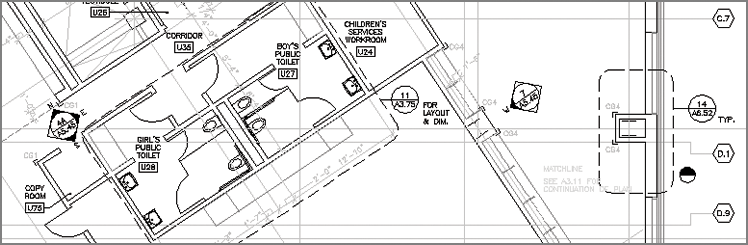
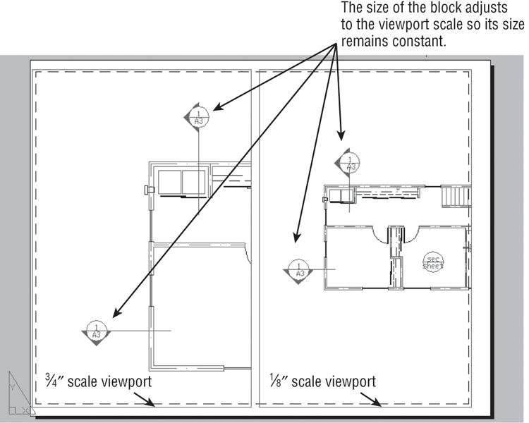
The Annotation Scale drop-down list appears in model view, and the Viewport Scale drop-down list appears in layout view and when a viewport is selected. (See Chapter 16, “Laying Out Your Printer Output,” for more about layouts and viewports.) In layout view, you can set the Viewport Scale value for each individual viewport so the same block can appear at the appropriate size for different scale viewports (see Figure 4-15).
Note that if you want to use several copies of a block that is using multiple annotation scales, you should insert the block and assign the additional annotation scales and then make copies of the block. If you insert a new instance of the block, the block acquires only the annotation scale that is current for the drawing. You’ll have to assign additional annotation scales to each new insertion of the block.
Figure 4-14 The Annotation Scale and the layout view’s Viewport Scale drop-down lists
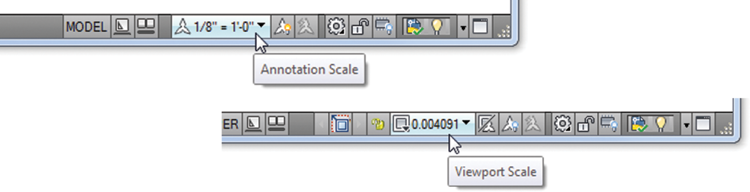
Figure 4-15 A single block is used to create building section symbols of different sizes in these layout views. Both views show the same floor plan displayed at different scales.
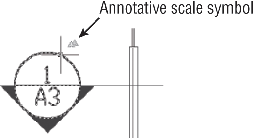
If you’re uncertain whether an annotation scale has been assigned to a block, you can click the block and you’ll see the different scale versions of the block as ghosted images. Also, if you hover over a block, triangular symbols appear next to the cursor for blocks that have been assigned annotation scales.
If you need to change the position of a block for a particular layout viewport scale, go to model view, select the appropriate scale from the Annotation Scale drop-down list, and then adjust the position of the block.
Grouping Objects
Blocks are extremely useful tools, but for some situations, they’re too restrictive. At times, you’ll want to group objects so that they’re connected but can still be edited individually. For example, consider a space planner who has to place workstations on a floor plan. Although each workstation is basically the same, some slight variations in each station could make the use of blocks unwieldy. For instance, one workstation might need a different configuration to accommodate special equipment, and another workstation might need to be slightly larger than the standard size. You would need to create a block for one workstation and then, for each variation, explode the block, edit it, and create a new block.

A better way is to draw a prototype workstation and turn it into a group. You can copy the group into position and then edit it for each individual situation without losing its identity as a group. AutoCAD LT® offers a different method for grouping objects. If you’re using AutoCAD LT, skip this exercise and continue with the following section, “Working with the AutoCAD LT Group Manager.”
The following exercise demonstrates how grouping works:
Figure 4-16 A workstation in an office plan
Now, whenever you want to select the workstation, you can click any part of it to select the entire group. At the same time, you can still modify individual parts of the group—the desk, partition, and so on—without losing the grouping of objects (see the next section, “Modifying Members of a Group”).
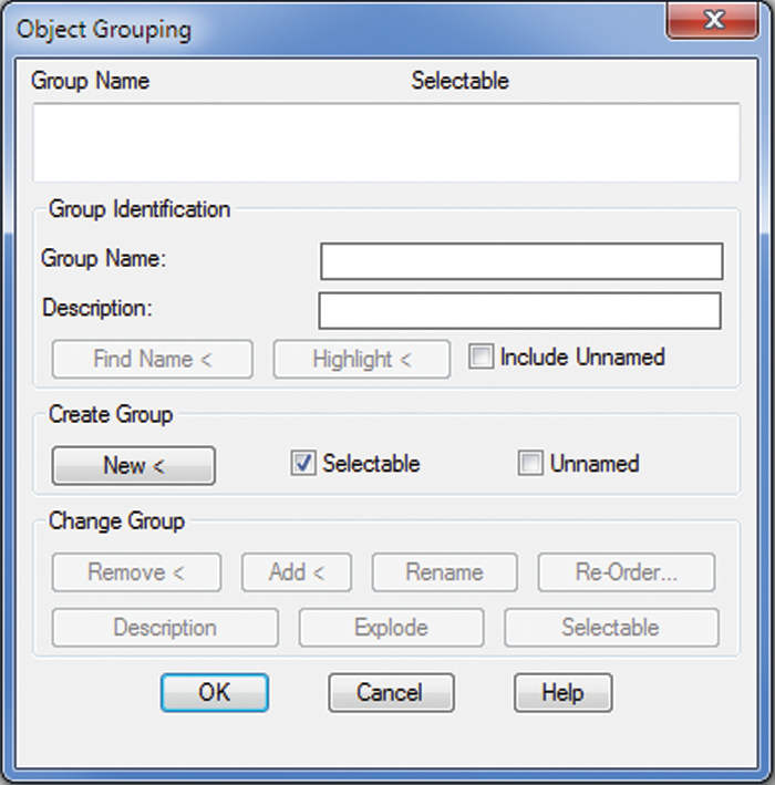
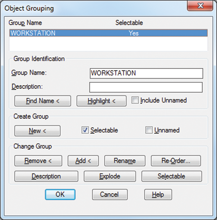
Another way to create a group is to use the Object Grouping dialog box (see Figure 4-17). Click Group Manager on the Home tab’s expanded Groups panel or type CLASSICGROUP↵ to open it.
Enter a name for your group in the Group Name text box, and then click the New button. The dialog box will temporarily disappear, allowing you to select the objects for your group. Once you’ve selected the objects, press ↵ to return to the dialog box. Click OK to complete the creation of the group.
Figure 4-17 Object Grouping dialog box
Modifying Members of a Group
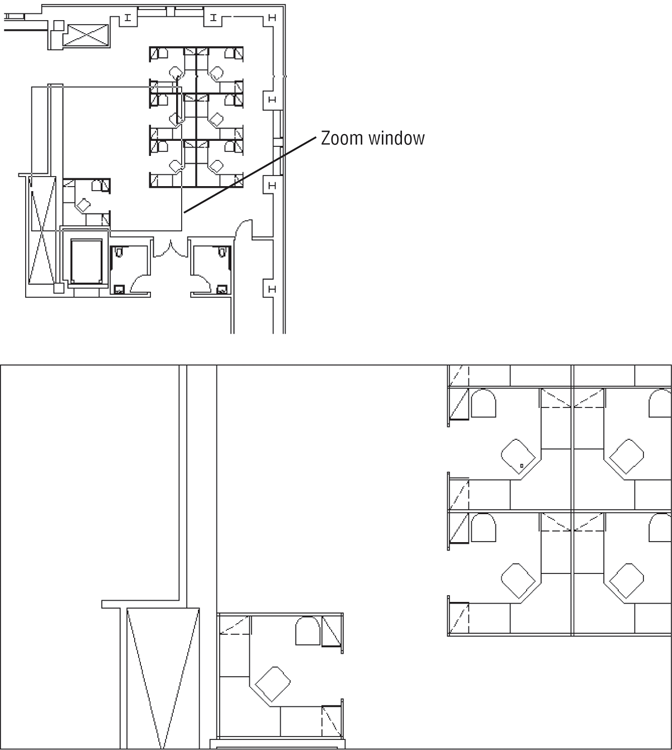
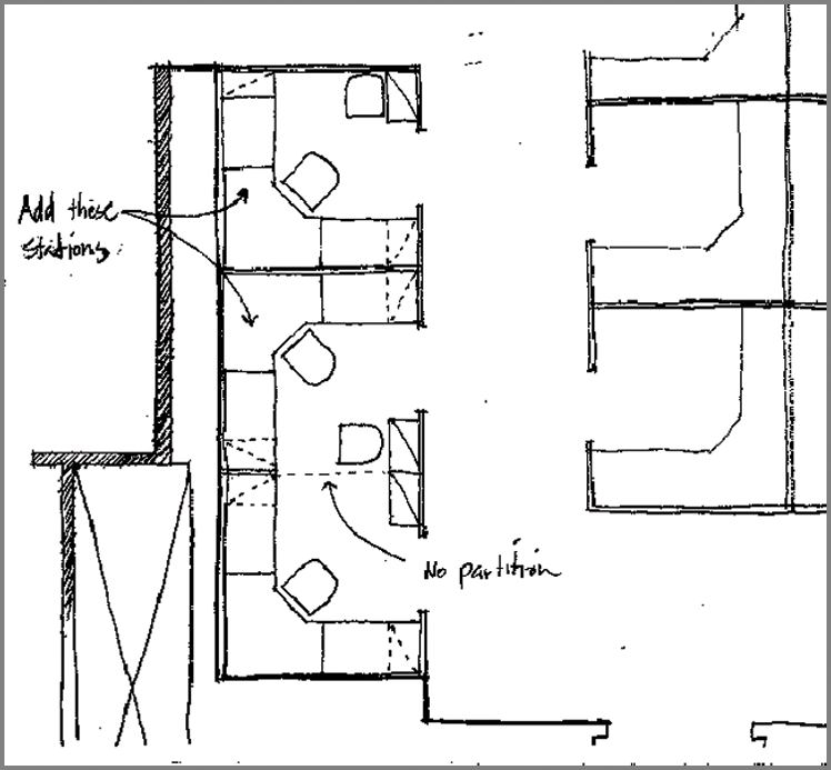
Next you’ll make copies of the original group and modify the copies. Figure 4-18 is a sketch of the proposed layout that uses the new workstations. Look carefully and you’ll see that some of the workstations in the sketch are missing a few of the standard components that exist in the Station1 group. One pair of stations has a partition removed; another station has one less chair.
The exercises in this section show you how to complete your drawing to reflect the design requirements of the sketch.
Start by making a copy of the workstation:
Figure 4-18 A sketch of the new office layout
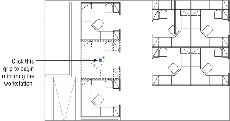
Next you’ll use grips to mirror the first workstation copy:
Figure 4-19 Selecting the grip to mirror the group
Now that you’ve got the workstations laid out, you need to remove some of the partitions between the new workstations. If you had used blocks for the workstations, you would first need to explode the workstations that have partitions you want to edit. Groups, however, let you make changes without undoing their grouping.
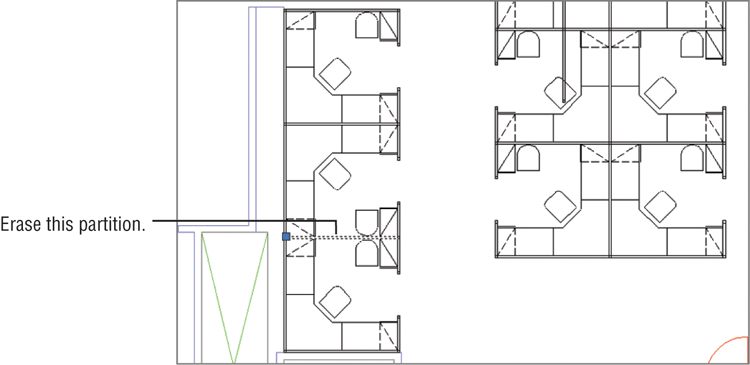
Use these steps to remove the partitions:
Figure 4-20 Remove the partitions between the two workstations.
Besides pressing Shift+Ctrl+A to turn groups on and off, you can click the Group Selection On/Off tool in the Home tab’s Groups panel. This tool changes the setting for Pickstyle. Pickstyle is a system variable that controls how groups are selected.
Ungrouping, Adding, and Subtracting From a Group
There are a few other tools in the Groups panel that will come in handy when working with groups (Figure 4-21). The Ungroup tool does exactly what it says: It will “ungroup” a group. Click the Ungroup tool or type UNGROUP↵, and then select the group or groups you want to ungroup.
Figure 4-21 The tools on the Home tab’s Groups panel
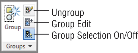
The Group Edit tool enables you to add or subtract objects from a group. You can also rename a group with this tool. Click the Group Edit tool or enter GROUPEDIT↵, select the group you want to edit, and then use the Add, Remove, or Rename option from the Dynamic Input menu that appears at the cursor. You can also type A↵, R↵, or REN↵ to add to, remove from, or rename a group, respectively.
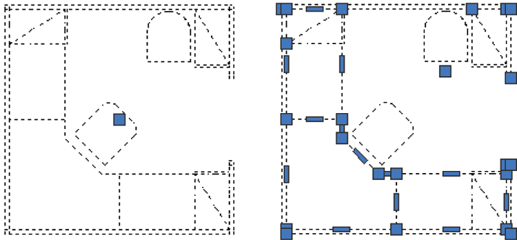
The Groups panel can be expanded to display the Group Manager and Group Bounding Box options. The Group Manager tool opens the Object Grouping dialog box. If you’ve used the Group command in earlier versions of AutoCAD, you’ll recognize this as the old Group command. The Group Bounding Box option toggles the way groups are displayed. You can view groups with the grips of all objects displayed, which is how groups were displayed in prior releases of AutoCAD, or you can display groups with a single grip and a bounding box (see Figure 4-22).
Figure 4-22 Groups in a bounding box (left) and with all the grips displayed (right)
Working with the Object Grouping Dialog Box
Each group has a unique name, and you can also attach a brief description of a group in the Object Grouping dialog box. When you copy a group, AutoCAD assigns an arbitrary name to the newly created group. Copies of groups are considered unnamed, but you can still list them in the Object Grouping dialog box by clicking the Include Unnamed check box. You can click the Rename button in the Object Grouping dialog box to name unnamed groups appropriately (see Figure 4-23). Click the Group Manager tool in the Home tab’s Groups panel or type CLASSICGROUP↵ to open the Object Grouping dialog box.
Figure 4-23 The Object Grouping dialog box
Objects in a group aren’t bound solely to that group. One object can be a member of several groups, and you can have nested groups (groups within groups).
AutoCAD LT users have a different set of options. See the next section, “Working with the AutoCAD LT Group Manager.”
Table 4-2 gives a rundown of the options available in the Object Grouping dialog box.
Table 4-2: Object Grouping dialog box options
| Option | Purpose |
| Group Name list | This list shows the names of groups in the drawing. You can click on the name to edit a group. |
| Group Identification | Use these options to identify your groups with unique elements that let you remember what each group is for. |
| Group Name | This text box lets you create a new group by naming it first. |
| Description | This text box lets you include a brief description of the group. |
| Find Name < | Click this button to find the name of a group. The Object Grouping dialog box temporarily closes so you can click a group. |
| Highlight < | Click this button to highlight a group that has been selected from the Group Name list. This helps you locate a group in a crowded drawing. |
| Include Unnamed | This check box determines whether unnamed groups are included in the Group Name list. Check this box to display the names of copies of groups for processing by this dialog box. |
| Create Group | Here’s where you control how a group is created. |
| New < | Click this button to create a new group. The Object Grouping dialog box closes temporarily so that you can select objects for grouping. To use this button, you must have either entered a group name or selected the Unnamed check box. |
| Selectable | This check box lets you control whether the group you create is selectable. See the description of the Selectable button in the Change Group panel later in this table. |
| Unnamed | This check box lets you create a new group without naming it. |
| Change Group | These buttons are available only when a group name is highlighted in the Group Name list at the top of the dialog box. |
| Remove < | Click this button to remove objects from a group. |
| Add < | Click this button to add objects to a group. While you’re using this option, grouping is temporarily turned off to allow you to select objects from other groups. |
| Rename | Click this button to rename a group. |
| Re-Order | Click this button to change the order of objects in a group. The order refers to the order in which you selected the objects to include in the group. You can change this selection order for special purposes such as tool-path machining. |
| Description | Click this button to modify the description of a group. |
| Explode | Click this button to separate a group into its individual components. |
| Selectable | Click this button to turn individual groupings on and off. When a group is selectable, it can be selected only as a group. When a group isn’t selectable, the individual objects in a group can be selected, but not the group. |
If a group is selected, you can remove individual items from the selection with a Shift+click. In this way, you can isolate objects within a group for editing or removal without having to turn off groups temporarily.
Working with the AutoCAD LT Group Manager
If you’re using AutoCAD LT, you use the Group Manager to manage groups. Table 4-3 offers a rundown of the tools that are available in the Group Manager.
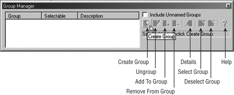
Table 4-3: AutoCAD LT 2014 Group Manager options
| Option | Purpose |
| Create Group | Lets you convert a set of objects into a group. Select a set of objects, and then click Create Group. |
| Ungroup | Removes the grouping of an existing group. Select the group name from the list, and then select Ungroup. |
| Add To Group | Lets you add an object to a group. At least one group and one additional object must be selected before this option is available. |
| Remove From Group | Lets you remove one or more objects from a group. To isolate individual objects in a group, first select the group and then Shift+click to remove individual objects from the selection set. After you isolate the object you want to remove, click Remove From Group. |
| Details | Lists detailed information about the group, such as the number of objects in the group and whether it’s in Model space or a layout. Select the group name from the group list, and then click Details. |
| Select Group | Lets you select a group by name. Highlight the group name in the group list, and then click Select Group. |
| Deselect Group | Removes a group from the current selection set. Highlight the group name in the group list, and then click Deselect Group. |
| Help | Opens the AutoCAD LT Help website and displays information about the Group Manager. |
You’ve seen how you can use groups to create an office layout. You can also use groups to help you keep sets of objects temporarily together in a complex drawing. Groups can be especially useful in 3D modeling when you want to organize complex assemblies together for easy selection.