
Chapter 1
Getting into Alternating Current
IN THIS CHAPTER
![]() Looking at alternating current
Looking at alternating current
![]() Glimpsing at the history of how alternating current won out over direct current
Glimpsing at the history of how alternating current won out over direct current
![]() Examining how an alternator can convert mechanical power to alternating current
Examining how an alternator can convert mechanical power to alternating current
![]() Discovering how electric motors work
Discovering how electric motors work
![]() Unveiling the magic of transformers
Unveiling the magic of transformers
A few years ago, I saw one of my favorite musicals, Les Misérables. It has nothing to do with electricity, of course, but at the end of the first act, as the daring gang of revolutionary college students join the rest of the characters singing “One Day More!,” they do a really cool marching step in which they march one pace toward the audience, then one pace back, one pace forward, one pace back, and so on. It creates a convincing effect of a mob on the move, even though the mob isn’t going anywhere.
That’s how alternating current works. So far in this book, I’ve focused mostly on working with direct current, in which the electric current flows in one direction and one direction only. If the revolutionaries in Les Misérables were demonstrating direct current, they would march straight off the stage, over the orchestra pit, and through the audience, out the back doors of the auditorium.
In alternating current, the current flows in both directions — forward and backward — much as the revolutionaries march one step at a time forward and backward.
Alternating current is of vital importance in electronics for one simple reason: The electric current you can access by plugging a circuit into a wall outlet happens to be alternating current. Thus, if you want to free your circuits from the tyranny of batteries, which eventually die, you’ll need to learn how to make your circuits work from an alternating current power supply.
In this chapter, you take a look at the nature of alternating current and how it can deliver reliable voltage to your home or place of business. You can also look at three fundamental alternating current devices: alternators, which generate alternating current from a source of motion such as a steam turbine or windmill; motors, which turn alternating current into motion; and transformers, which can transfer alternating current from one circuit to another without any physical connection between the circuits. And finally, you learn about the basics of working with alternating current safely.
Incidentally, if you want to see the famous Les Misérables march step in action, go to YouTube, search Les Miserables Tony Awards, and choose the first hit that comes up. You’ll see the marching about 3 minutes into the video. (The video is also cool because it’s introduced by Jerry Orbach, before he landed the part of Lenny Briscoe on Law and Order.)
What Is Alternating Current?
As you know, electric current that flows continuously in a single direction is called a direct current, or DC. In a direct current circuit, current is caused by electrons that all line up and move in one direction. Within a wire carrying direct current, electrons hop from atom to atom while moving in a single direction. Thus, a given electron that starts its trek at one end of the wire will eventually end up at the other end of the wire.
In alternating current, the electrons don’t move in only one direction. Instead, they hop from atom to atom in one direction for awhile, and then turn around and hop from atom to atom in the opposite direction. Every so often, the electrons change direction. In alternating current, the electrons don’t move steadily forward. Instead, they just move back and forth.
When the electrons in alternating current switch direction, the direction of current and the voltage of the circuit reverses itself. In public power distribution systems in the United States (including household current), the voltage reverses itself 60 times per second. In some countries, the voltage reverses itself 50 times per second.
The rate at which alternating current reverses direction is called its frequency, expressed in hertz. Thus, standard household current in the United States is 60 Hz.
It’s important to realize that the voltage in an alternating current circuit doesn’t instantly reverse polarity. Instead, the voltage steadily increases from zero until it reaches a maximum voltage, which is called the peak voltage. Then, the voltage begins to decrease again back to zero. The voltage then reverses polarity and drops below zero, again heading for the peak voltage but negative polarity. When it reaches the peak negative voltage, it begins climbing back again until it gets to zero. Then the cycle repeats.
The swinging change of voltage is important because of the basic relationship between magnetic fields and electric currents. When a conductor (such as a wire) moves through a magnetic field, the magnetic field induces a current in the wire. But if the conductor is stationary relative to the magnetic field, no current is induced.
Physical movement is not necessary to create this effect. If the conductor stays in a fixed position but the intensity of the magnetic field increases or decreases (that is, if the magnetic field expands or contracts), a current is induced in the conductor the same as if the magnetic field were fixed and the conductor was physically moving across the field.
Because the voltage in an alternating current is always either increasing or decreasing as the polarity swings from positive to negative and back again, the magnetic field that surrounds the current is always either expanding or collapsing. So, if you place a conductor within this expanding and collapsing magnetic field, current will be induced in the conductor. And that current will alternate in concert with the movement of the magnetic field.
It seems like magic! With alternating current, it is possible for current in one wire to induce current in an adjacent wire, even though there is no physical contact between the wires.
The bottom line is this: Alternating current can be used to create a changing magnetic field, and changing magnetic fields can be used to create alternating current. This relationship between alternating current and magnetic fields makes three important devices possible:
- Alternator: A device that generates alternating current from a source of rotating motion, such as a turbine powered by flowing water or steam or a windmill. Alternators work by using the rotating motion to spin a magnet that’s placed within a coil of wire. As the magnet rotates, its magnetic field moves, which induces an alternating current in the coiled wire. (Coils of wires are used instead of straight wires simply because coiling up the wire allows a greater length of wire to be exposed to the changing magnetic field.)
- Motor: The opposite of an alternator. It converts alternating current to rotating motion. In its simplest form, a motor is simply an alternator that’s connected backward. A magnet is mounted on a shaft that can rotate; the magnet is placed within the turns of a coil of wire. When alternating current is applied to the coil, the rising and falling magnetic field created by the current causes the magnet to spin, which turns the shaft.
- Transformer: Consists of two coils of wire placed within close proximity. If an alternating current is placed on one of the coils, the collapsing and expanding magnetic field will induce an alternating current in the other coil.
Measuring Alternating Current
With direct current, it’s easy to determine the voltage that’s present between two points: You simply measure the voltage with a voltmeter.
With alternating current, however, measuring the voltage isn’t so simple. That’s because the voltage in an alternating current circuit is constantly changing. So, for example, when we say that the voltage at a wall receptacle is 120 VAC, what does that really mean?
There are actually three ways you can measure voltage in an AC circuit. They are illustrated in Figure 1-1. The three ways are:
- Peak voltage: A measurement of the largest voltage present between 0 V and the highest point on the AC cycle. It’s the maximum voltage that the AC voltage attains.
- Peak-to-peak voltage: The difference between the highest and lowest peaks of the AC voltage. In most AC voltages, the peak-to-peak voltage is double the peak voltage.
-
RMS voltage: The average voltage of the circuit; also called the mean voltage. RMS stands for root mean square, but that’s important only if you’re studying for an exam or something. RMS voltage is far and away the most common way to specify the voltage of an AC circuit. For example, when we say that the voltage at a household electrical outlet is 120 VAC, what we really mean is that the RMS voltage is 120 V.
If the AC voltage follows a true sine wave, the RMS voltage is equal to 0.707 times the peak voltage. Or to turn it around, the peak voltage is equal to about 1.4 times the RMS voltage. Thus, the actual peak voltage at a household electrical outlet is about 168 V.

FIGURE 1-1: Three ways to measure alternating current.
 The true RMS voltage is a bit tricky to calculate, since it involves some fairly complicated math. RMS is calculated by sampling the actual voltage in very small time increments. Then, the sample voltages are squared, the squares of the voltages are added up, and the average of all the squared values is calculated. Finally, the square root of the average is calculated. This is the actual RMS value.
For a true sine wave, the preceding calculation turns out to be very close to multiplying the peak voltage by 0.707. For AC voltages that aren’t true sine waves, however, the actual RMS value can be different than the “multiply by 0.707” shortcut would indicate.
Nearly all AC voltmeters report the RMS voltage, but only more expensive AC voltmeters calculate the actual RMS by sampling the input voltage and doing the sum-of-the-squares thing. Inexpensive voltmeters simply measure the peak voltage and multiply it by 0.707. Fortunately, this is close enough for most purposes.
Understanding Alternators
One good way to get your mind around how alternating current works is to look at the device that’s most often used to generate it: the alternator. An alternator is a device that converts rotary motion, usually from a turbine driven by water, steam, or a windmill, into electric current. By its very nature, an alternator creates alternating current.
Figure 1-2 shows a simplified diagram of how an alternator works. Essentially, a large magnet is placed within a set of stationary wire coils. The magnet is mounted on a rotating shaft that’s connected to a turbine or windmill. Thus, when water or steam flows through the turbine or when wind turns the windmill, the magnet rotates.

FIGURE 1-2: An alternator generates alternating current from a rotating magnet.
As the magnet rotates, its magnetic field moves across the coils of wire. Because of the phenomenon of electromagnetic induction, the moving magnetic field induces an electric current within the wire coils. The strength and direction of this electric current depends on the position and direction of the rotating magnet.
In Figure 1-2, you can see how the current is induced in the wire at four different positions of the magnet’s rotation. In part A, the magnet is at its farthest point away from the coils and oriented in the same direction as the coils. At this moment, the magnetic field doesn’t induce any electric current at all. Thus, the light bulb is dark.
But as the magnet begins to rotate clockwise, the magnet comes closer to the coils, thus exposing more of its magnetic field to the coils. The moving magnetic field induces a current that gets stronger as the magnet continues to rotate closer to the coils. This causes the light bulb to glow. Soon, the magnet reaches its closest point to the coils, as shown in part B. At this point, the current and the voltage are at their maximum, and the light bulb glows at its brightest.
As the magnet continues to rotate counterclockwise, it now begins to move away from the coil. The moving electric field continues to induce current in the coil, but the current (and the voltage) decreases as the magnet retreats farther away from the coils. When the magnet reaches its farthest point from the coils, shown in part C, the current stops and the light bulb goes dark.
As the magnet continues to rotate, it now gets closer again to the coils. But this time, the polarity of the magnet is reversed. Thus, the electric current induced in the wire by the moving magnetic field is in the opposite direction, as shown in part D. Once again, the light bulb glows as the current passing through it increases.
And so on. With each revolution of the magnet, voltage starts at zero and rises steadily to its maximum point, then falls until it reaches zero again. Then the process is reversed, with the current flowing in the opposite direction.
Here are a few other interesting tidbits about alternators:
- The term generator refers to any device that converts mechanical energy into electrical energy. An alternator is a specific type of generator, so it is common — and correct — to refer to an alternator as a generator.
- It’s possible to generate direct current from rotating magnetic fields. A DC generator is more complex than an alternator, however, and contains additional components that can wear out over time.
- The frequency of the alternating current generated by an alternator is dictated by the rate at which the magnet rotates. The faster the magnet rotates, the higher the frequency of the resulting alternating current.
- If you place two sets of coils spaced evenly around the magnet, each forming its own complete circuit, alternating current will be induced in each set of coils. However, the polarities of the two voltages will be mirror images of one another. In other words, when the voltage is positive in one of the circuits, it will be negative in the other. The relationship between the polarity of the circuits is called a phase, and a power-generating system with two circuits arranged in this way is called a two-phase system. The two circuits are said to be 180° out of phase with one another.
- If three sets of coils are used, the system is called a three-phase system. In a three-phase system, the three circuits are 120° out of phase. Most public power-generation systems are three-phase systems because that results in the most efficient generation of power from the rotating magnetic fields.
Understanding Motors
An electric motor converts electrical energy in the form of electric current to rotating mechanical energy. The simplest type of electric motor is essentially the same thing as an alternator. The difference is that instead of using some other mechanical force such as water or steam to turn the magnet — which in turn induces electric current in the coils — electric current is applied to the coils, which in turn causes the magnet to rotate.
I would show you a diagram depicting the operation of a motor, but it would look pretty much like the alternator diagram shown in Figure 1-2. The only difference would be that the light bulb would be replaced by an AC power source. The same force that causes an electric current to be induced in a coil when the coil passes through a moving magnetic field causes a moving magnetic field to be created when a current is passed through a coil. The moving magnetic field, in turn, causes the magnet to rotate. This rotation is transferred to the shaft to which the magnet is attached.
As with alternators, it’s also possible to create motors that work with DC circuits instead of AC. As with alternators, DC motors are more complicated than AC motors. In a DC motor, the polarity of the coils must be reversed every half-revolution of the magnet to keep the magnet moving in complete rotations. Usually, metal brushes are used to do this. In an AC motor, the brushes aren’t necessary because the alternating current reverses polarity on its own.
Understanding Transformers
In Book 2, Chapter 4, you learn about the basic principles of magnetism and inductance. A transformer is a device that exploits these two principles:
- A changing current passing through a wire creates a moving magnetic field around the wire.
- A changing current will be induced in a wire that’s exposed to a moving magnetic field.
A transformer combines these two principles by placing two coils of wire in close proximity to one another, as shown in Figure 1-3. When a source of AC is connected to one of the coils, that coil creates a magnetic field that expands and collapses in concert with the changing voltage of the AC. In other words, as the voltage increases across the coil, the coil creates an expanding magnetic field. When the voltage reaches its peak and begins to decrease, the magnetic field created around the coil begins to collapse.

FIGURE 1-3: A transformer uses magnetic induction to pass current from one circuit to another.
The second coil is located within the magnetic field created by the first coil. As the magnetic field expands, it induces current in the second coil. The voltage across the second coil increases as long as the magnetic field expands. When the magnetic field begins to collapse, the voltage across the second coil begins to decrease.
Thus, the current induced in the second coil mirrors the current that is passed through the first coil. A small amount of energy is lost in the process, but if the transformer is well constructed, the strength of the current induced in the second coil is very close to the strength of the current passed through the first coil.
The first coil in a transformer — the one that’s connected to the AC voltage — is called the primary coil. The second coil — the one in which an AC voltage is induced — is called the secondary coil. All transformers have both a primary and a secondary coil.
One of the most useful characteristics of a transformer is that the voltage induced in the secondary coil is equal to the voltage applied to the primary coil times the ratio of the number of turns in the primary coil and the second coil.
In the simplest case, where both the primary and secondary coils have the same number of turns, the voltage induced in the secondary coil will be the same as the voltage applied to the primary coil. But what if the primary coil has more turns than the secondary coil? In that case, the voltage induced in the secondary coil will be less than the voltage applied to the primary.
How much less depends on the ratio of the turns in the primary and secondary coils. If the secondary coil has half as many turns as the primary coil, the voltage induced in the secondary coil will be half the voltage applied to the primary coil. For example, if you apply 110 VAC to the primary coil, 55 VAC will be induced in the secondary coil.
Likewise, if the secondary coil has more turns than the primary coil, the induced voltage will be more than the voltage applied to the primary coil. For example, suppose the primary coil has 1,000 turns and the secondary coil has 2,000 turns. Then, if you apply 110 V to the primary coil, 220 V will be induced in the secondary coil.
A transformer whose primary coil has more turns than its secondary coil is called a step-down transformer because it reduces voltage — that is, the voltage at the secondary coil is less than the voltage at the primary coil. Similarly, a transformer that has more turns in the secondary than in the primary is called a step-up transformer because it increases voltage.
Although the voltage increases in a step-up transformer, the current is reduced proportionately. For example, if the primary coil has half as many turns as the secondary coil, the voltage induced in the secondary coil will be twice the voltage that’s applied to the primary coil, but the current that flows through the secondary coil will be half the current flowing through the primary coil.
Similarly, when the voltage decreases in a step-down transformer, the current increases proportionately. Thus, if the voltage is cut in half, the current doubles.
This makes perfect sense when you think about it. After all, a transformer can’t just conjure up power out of thin air. If it could, we’d have solved the planet’s energy problems long ago. But there is no such thing as free energy.
Remember the basic formula for calculating electric power:
In other words, power equals voltage times current. A transformer transfers power from the primary coil to the secondary coil. Since the power must stay the same, if the voltage increases, the current must decrease. Likewise, if the voltage decreases, the current must increase.
Transformers are the main reason we use alternating current instead of direct current in large power distribution systems. That’s because when you send large amounts of power over a long distance, it’s much more efficient to send the power in the form of high voltage and low current. That’s why overhead power transmission lines often carry voltages as high as 400,000 VAC. Such high voltages allow the electrical power to be transmitted using much smaller wires than would be required if the same amount of power were transmitted at 120 VAC.
Power distribution systems use large step-up transformers to step voltages generated at power plants up to thousands or hundreds of thousands of volts. Then, as the power gets closer to its final destination (such as your house), a series of step-down transformers drops the voltage down to more manageable levels, until the voltage is dropped to its final level (120 VAC) before it enters your house.
 Transformers work only with alternating current. That’s because it’s the change of the magnetic field created by the primary coil that induces voltage in the secondary coil. To create a changing magnetic field, the voltage applied to the primary coil must be constantly changing. Because DC is a steady, fixed voltage, it creates a fixed magnetic field that won’t induce voltage in the secondary coil.
Working with Line Voltage
Line voltage refers to the voltage that’s available in standard residential or commercial wall outlets. In the United States, this voltage is almost always in the neighborhood of 120 VAC, though it’s commonly referred to as 110 VAC, 115 VAC, or 117 VAC. In other parts of the world, the voltage may be lower or higher.
 In Europe, line voltage is often referred to as mains voltage or just mains.
Unlike the voltage available from household batteries, line voltage is dangerous. In fact, if you’re not careful, line voltage can kill you. Thus, you need to take precautions whenever you build a circuit that works with line voltage. In this chapter, you learn how to use line voltage safely so that neither you nor anyone else gets hurt.
Using Line Voltage in Your Projects
So far, none of the projects presented in this book have involved the use of line voltage. But many — if not most — real-world projects do require that you use line voltage.
The most common reason for using line voltage in a project is to eliminate the need for batteries. Batteries are a convenient source of power for your circuits, but they wear out. For many circuits, you want to provide a power source that will last indefinitely. If you use batteries, they’ll eventually lose their charge and have to be replaced. If you use line voltage, you can plug the project in and not have to worry about changing batteries.
Of course, most electronic components require direct current rather than alternating current, and at much lower voltage levels than the levels that line voltage supplies. Thus, for your project to use line voltage as its source of power, you need to provide the project with a power supply that converts the 120 VAC line voltage to something more useful, such as 5 VDC.
There are at least two ways to accomplish this:
- By using a power adapter: The easiest way is to use an external power adapter, often called a wall wart or a power brick. Figure 1-4 shows a typical external power adapter. You can purchase power adapters from just about any store that has a consumer electronics department. Just get one that provides the right level of DC voltage and use it instead of batteries.
- By building your own power supply: The alternative to purchasing a power adapter is to build your own power supply circuit. This circuit must accomplish two things. First, it must step the voltage down from 120 VAC to whatever voltage your circuit requires, and second, it must convert the AC voltage to DC voltage. You learn how to design and build a power supply circuit in the next chapter.

FIGURE 1-4: An external power adapter.
The second common reason for using line voltage in a project is if the project needs to control some external device that runs on line voltage, such as a flood lamp or a pump. In that case, your project needs to be able to turn the line voltage on and off.
The most common way to turn a line voltage device on and off from an electronic circuit is to use a device called a relay, which is basically an electronic switch that uses a low-current input to control a high-current output. For example, a relay can let you use a 12 VDC circuit to control a separate line voltage circuit. You learn how to use a relay for this purpose later in this chapter, in the section “Using Relays to Control Line-Voltage Circuits.”
Being safe with line voltage
Whenever you build an electronics project that uses line voltage, you must take extra precautions to ensure your safety and the safety of anyone who may come in contact with your project. Line voltage is potentially deadly, so these precautions are absolutely mandatory.
 Many people are under the mistaken belief that line voltage is not sufficient to cause serious injury or death. That simply isn’t true; 120 VAC is more than enough voltage to kill, given the right conditions. In fact, you should treat any voltage above 50 V as potentially lethal.
When you work with line voltage, be sure to take the following precautions:
- Never work on the circuit when the power plug is plugged in.
- Never leave exposed line-voltage connections anywhere that you or anyone who comes into contact with your project might accidentally touch. All line-voltage connections must be completely insulated or contained within an insulated project box or a grounded metal project box.
- Always enclose projects that use line voltage in a sealed project box so that stray hands can’t accidentally come in contact with bare wires or other components.
- Always use grounded power cords if your project is contained in a metal box, and always connect the metal box itself to the power cord’s ground lead.
- Always use the correct gauge of wire for the amount of current your circuit will be carrying. For more information, see the section, “Wires and Connectors for Working with Line Voltage.”
- Always ensure that all line-voltage connections are tight and secure. If you’re using stranded wire instead of solid wire, always check for stray strands at your connections.
- Always provide some form of strain-relief for wires that carry line voltage. The most common way to do this is to pass the wire through a grommet-protected hole in the project box and tie the wire into a knot inside the box. The knot will prevent the cord from sliding through the hole in the case and possibly pulling loose.
- Always incorporate a fuse in the primary side of your line-voltage circuit. The fuse will automatically detect when too much current is flowing and immediately break the circuit.
- Never use a fuse that’s rated for more than the maximum current your circuit is designed to bear. For example, if you’re using a relay that can switch 5 A of current, use a fuse rated for 5 A or less. (For more on fuses, see the section, “Using Fuses to Protect Line-Voltage Circuits,” later in this chapter.)
- Never arrange the wiring for your project in a way that causes wires to move or rub against one another. The rubbing will eventually wear off the insulation and create a shock hazard.
- Always be aware of heat sinks that may be hot.
- Never use a three-prong to two-prong adapter to plug a three-prong power connector into a two-prong extension cord. This disables the safety provided by proper grounding and can result in a potentially fatal electric shock if a short circuit occurs.
Understanding hot, neutral, and ground
Before you start working with line voltage in your circuits, you need to understand a few details about how most residential and commercial buildings are wired. The following description applies only to the United States; if you’re in a different country, you’ll need to determine the standards for your country’s wiring.
Standard line voltage wiring in the United States is done with plastic-sheathed cables, which usually have three conductors, as shown in Figure 1-5. This type of cable is technically called NMB cable, but most electricians refer to it using its most popular brand name, Romex.
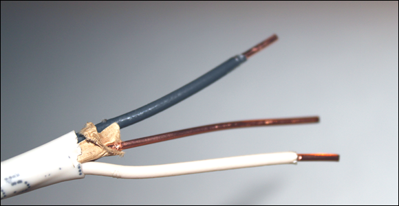
FIGURE 1-5: NMB cabling.
Two of the conductors in NMB cable are covered with plastic insulation (one white, the other black). The third conductor is bare copper. These conductors are designated as follows:
- Hot: The black wire is the hot wire, which provides a 120 VAC current source.
- Neutral: The white wire is called the neutral wire. It provides the return path for the current provided by the hot wire. The neutral wire is connected to an earth ground.
- Ground: The bare wire is called the ground wire. Like the neutral wire, the ground wire is also connected to an earth ground. However, the neutral and ground wires serve two distinct purposes. The neutral wire forms a part of the live circuit along with the hot wire. In contrast, the ground wire is connected to any metal parts in an appliance such as a microwave oven or coffee pot. This is a safety feature, in case the hot or neutral wires somehow come in contact with metal parts. Connecting the metal parts to earth ground eliminates the shock hazard in the event of a short circuit.
Note that some circuits require a fourth conductor. When a fourth conductor is used, it’s covered with red insulation and is also a hot wire.
The three wires in a standard NMB cable are connected to the three prongs of a standard electrical outlet (properly called a receptacle), as shown in Figure 1-6. As you can see, the neutral and hot wires are connected to the two vertical prongs at the top of the receptacle (neutral on the left, hot on the right) and the ground wire is connected to the round prong at the bottom of the receptacle.

FIGURE 1-6: A standard electrical receptacle.
You can plug a two-prong or three-prong plug into a standard three-prong receptacle. Two-prong plugs are designed for appliances that don’t require grounding. Most nongrounded appliances are double-insulated, which means that there are two layers of insulation between any live wires and any metal parts within the appliance. The first layer is the insulation on the wire itself; the second is usually in the form of a plastic case that isolates the live wiring from other metal parts.
Three-prong plugs are for appliances that require the ground connection for safety. Most appliances that use a metal chassis require a separate ground connection.
There is only one way to insert a three-prong plug into a three-prong receptacle. But regular two-prong plugs, which lack the ground prong, can be connected with either prong on the hot side. To prevent that from happening, the receptacles are polarized, which means that the neutral prong is wider than the hot prong. Thus, there’s only one way to plug a polarized plug into a polarized receptacle. That way, you can always keep track of which wire is hot and which is neutral.
You should always place switches or fuses on the hot wire rather than on the neutral wire. That way, if the switch is open or the fuse blows, the current in the hot wire will be prevented from proceeding beyond the switch or fuse into your circuit. This minimizes any risk of shock that might occur if a wire comes loose within your project.
Wires and Connectors for Working with Line Voltage
When working with line voltage, you must always use wire that’s designed specifically to handle line-voltage currents. Depending on your needs, you may choose to use solid or stranded wire. Stranded wire is usually easier to work with because it’s more flexible.
When choosing wire, make sure you get the right gauge for the current your circuit will be carrying. For circuits that are designed to carry 15 A or less (which is the maximum current limit for devices plugged into most household electrical outlets), you can use 14-gauge wire. If the circuit will carry no more than 13 A, 16-gauge wire is sufficient. For less than 10 A, 18-gauge wire is sufficient.
Lamp wire, also known as zip cord, is the wire that lamp cords and indoor extension cords are made of. It’s usually two-conductor, nongrounded 16- or 18-guage stranded wire in which the two conductors are joined in a way that lets you easily peel them apart. Lamp wire is the easiest wire to use for short connections within your project. You can buy lamp wire in bulk at most hardware stores, or you can buy an inexpensive indoor extension cord at a discount dollar store and cut the ends off.
Make sure all connections you make with wires carrying line voltage are secure. The easiest way to connect the wires is to use wire nuts, illustrated in Figure 1-7. To use wire nuts, strip off 3/8 inch or so of insulation from the two wires to be connected and loosely twist the two ends together. Then, slip the wire nut over the twisted end and tighten the nut onto the connection by pushing down and twisting. When the wire nut is as tight as you can get it, check to make sure that none of the stripped wire extends below the base of the wire nut. For good measure, you can wrap a short strip of black electrical tape around the connection.

FIGURE 1-7: Wire nuts.
Another way to make connections is to use a barrier strip, as shown in Figure 1-8. Barrier strips come in various sizes and shapes. The small one pictured in the figure can make four connections; the larger one can make eight. To use a barrier strip, simply strip away a short length of insulation from the end of the wires you want to connect and secure them under the terminal screws. If you’re using stranded wire, make sure that all the strands are held by the screw. Loose strands can cause short circuits.
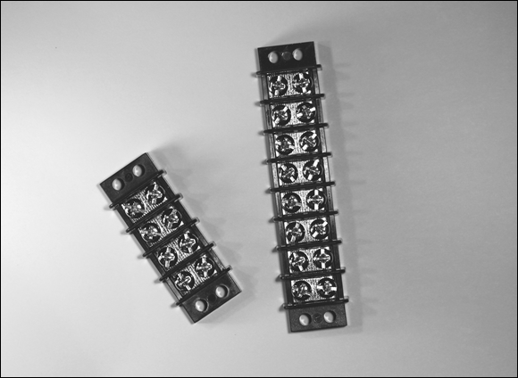
FIGURE 1-8: Barrier strips are useful for connecting wires that carry AC power.
Using Fuses to Protect Line-Voltage Circuits
A fuse is an inexpensive device that can carry only a certain amount of current. If the current exceeds the rated level, the fuse melts (blows), thus breaking the circuit and preventing the excessive current from flowing. Fuses are an essential component of any electrical system that uses line voltage and has the possibility of short-circuiting or overheating and causing a fire.
The most common type of fuse is the cartridge fuse, which consists of a cylindrical body that’s usually made of glass, plastic, or ceramic, with two metal ends. The metal ends are the two terminals of the fuse. Inside the body is a thin wire conductor that’s designed to melt if the current exceeds the rated threshold. As long as the current stays below the maximum level, the conductor passes the current from one metal end to the other. But when the current exceeds the rated maximum, the conductor melts, and the circuit is broken.
Figure 1-9 shows an AGC fuse, which is a small fuse made of glass, ![]() inches in length and
inches in length and ![]() inch in diameter. This particular fuse is rated at 2 A, but you can get AGC fuses in larger ratings, up to 15 A. (AGC stands for Automotive Glass Cartridge, but that won’t be on the test.)
inch in diameter. This particular fuse is rated at 2 A, but you can get AGC fuses in larger ratings, up to 15 A. (AGC stands for Automotive Glass Cartridge, but that won’t be on the test.)

FIGURE 1-9: A 2 A,  -inch AGC fuse.
Fuses should always be connected to the hot wire and should be placed before any other component in the circuit. In most projects, the fuse should be the first thing the hot wire connects to after it enters your project enclosure. Figure 1-10 shows how a fuse is depicted in a schematic diagram. Here, the fuse is placed on the hot wire before the lamp.

FIGURE 1-10: A fuse in a schematic diagram.
If you plan on using a fuse in your circuit, you’ll need to purchase a fuse holder to hold the fuse. For AGC cylindrical fuses, there are two distinct types of fuse holders to choose from. If the fuse will be mounted inside your project’s enclosure, you can use a chassis-type fuse holder. If you want the fuse to be accessible from outside the project’s enclosure, you should choose a panel-mount holder instead. Figure 1-11 shows both types of holders.

FIGURE 1-11: Fuse holders.
Using Relays to Control Line-Voltage Circuits
In many projects, you need to turn line-voltage circuits on and off using circuits that use low-voltage DC power supplies. For example, suppose you want to flash a 120 VAC flood lamp on and off at regular intervals. You could build a circuit to provide the necessary timing using a 555 timer IC as described in Book 3, Chapter 2, but the 555 timer IC requires just a small DC power supply, in the range of 5 to 15 V. And the output current can’t exceed 200 mA, not nearly enough to light a flood lamp.
Relays to the rescue!
A relay is an electromechanical device that uses an electromagnet to open or close a switch. The circuit that powers the electromagnet’s coil is completely separate from the circuit that is switched on or off by the relay’s switch, so it’s possible to use a relay whose coil requires just a few volts to turn a line voltage circuit on or off.
Figure 1-12 shows a typical relay. For this relay, the coil requires just 12 VDC to operate and pulls just 75 mA, well under the current limit that can be sourced by the 555 timer IC’s output pin. But the switch part of this relay can handle up to 10 A of current at 120 VAC, more than enough to illuminate a flood lamp.

FIGURE 1-12: A relay is a switch that is controlled by an electromagnet.
The switch part of a relay is available in different configurations just like manual switches. The most common switch configuration is double pole, double throw (DPDT), which means that the relay actually controls two separate switches that operate together, and that each switch has both normally open and normally closed contacts.
Figure 1-13 shows a schematic diagram for a simple circuit that uses a 9 VDC circuit with a handheld push button to turn a 120 VAC lamp on and off. The relay in the circuit has a coil rated for 9 VDC and a switch rating of 10 A at 117 VAC. Thus, only 9 VDC passes through the handheld push button. If the person holding the switch decides to take it apart, he or she won’t be exposed to dangerous voltage.

FIGURE 1-13: Using a relay to switch a line-voltage circuit.
Figure 1-14 shows a more complicated circuit, in which a 555 timer IC controls a flood lamp via a relay. Here, one end of the relay coil is connected to the 555 timer IC’s output pin (pin 3), and the other end is connected to ground. When the 555’s output switches on, the relay closes, and the flood lamp circuit is completed.

FIGURE 1-14: Driving a relay from a 555 timer IC.
Note the diode that’s placed across the relay coil in this circuit. This diode is required to protect the 555 timer IC from any back-current that might be created within the relay’s coil when the coil is energized. Because of electromagnetic induction, relay coils are prone to this problem.
When the coil is energized, it creates a magnetic field that causes the relay’s switch contacts to move. However, this magnetic field has a subtle side effect. In the instant that the voltage on the coil goes from zero to the Vss supply voltage, the magnetic field surrounding the coil expands from nothing to its maximum strength. During this expansion, the magnetic field is moving relative to the coil itself. Because of the principal of induction, this moving magnetic field induces a current in the coil itself, in the opposite direction as the current that is energizing the coil.
Depending on the circumstances, this back current can be powerful — powerful enough to overwhelm the output current coming from the 555 timer IC and possibly powerful enough to send current into the output pin, which can damage or destroy the 555 chip. D1 prevents this from happening by providing the equivalent of a short circuit across the coil for current flowing back toward the output pin.
Whenever you drive a relay from a circuit that has delicate components such as integrated circuits or transistors, you should always include a diode across the relay coil to prevent the relay from damaging your circuits.