
1
Introduction
1.1 UAV versus UAS
An unmanned aerial vehicle (UAV), also known as a drone, refers to a pilotless aircraft, a flying machine without an onboard human pilot or passengers. As such, ‘unmanned’ implies the total absence of a human who directs and actively pilots the aircraft. Control functions for unmanned aircraft may be either onboard or off-board (remote control). That is why the terms remotely operated aircraft (ROA) and remotely piloted vehicle (RPV) are in common use as well [1]. The term UAV has been used for several years to describe unmanned aerial systems. Various definitions have been proposed for this term, like [2]:
A reusable1 aircraft designed to operate without an onboard pilot. It does not carry passengers and can be either remotely piloted or pre-programmed to fly autonomously.
Recently, the most reputable international organizations – like the International Civil Aviation Organization (ICAO), EUROCONTROL, the European Aviation Safety Agency (EASA), the Federal Aviation Administration (FAA) – as well as the US Department of Defense (DoD), adopted unmanned aircraft system (UAS) as the correct official term. The changes in acronym are caused by the following aspects:
- The term ‘unmanned’ refers to the absence of an onboard pilot.
- The term ‘aircraft’ signifies that it is an aircraft and as such properties like airworthiness will have to be demonstrated.
- The term ‘system’ is introduced to signify that UAS is not just a vehicle but a (distributed) system consisting of a ground control station, communication links and launch and retrieval systems in addition to the aircraft itself.
Figure 1.1 A typical UAS [62]
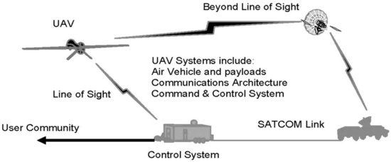
A typical UAS comprises system elements in three major segments, as shown in Figure 1.1.
- Air segment. This includes one or more unmanned aircrafts (UAs) with their payloads. Each UA includes the airframe, the avionics and propulsion system components. The payload consists of sensor components that support mission requirements; sensors include cameras, radar, altimeter, inertial measurement unit (IMU), global positioning system (GPS), antennas, etc.
- Ground segment. This refers to the ground control station (GCS), which includes components like the payload control station/ground data terminal (GDT) and, if necessary, the launch and recovery system (LRS). The GCS includes all required equipment for the UA pilot, flight planning and mission monitoring. It also translates pilot inputs into the appropriate commands to be transmitted over the communication link to the aircraft.
- Communications segment. This is divided into the Command & Control data link, the Payload data link and External Communications. The term ‘link’ may be defined based on the distance the UAS is operating at: visual line of sight (VLOS), line of sight (LOS) or beyond line of sight (BLOS).
The FAA defines an unmanned aircraft or UA as [3]:
A device used or intended to be used for flight in the air that has no onboard pilot. This includes all classes of airplanes, helicopters, airships, and translational lift aircraft that have no onboard pilot. Unmanned aircraft are understood to include only those aircraft controllable in three axes and therefore, exclude traditional balloons.
As a comparison, the definition of unmanned vehicle given in the 2007–2012 Unmanned Systems Roadmap is also provided [4]:
A powered vehicle that does not carry a human operator, can be operated autonomously or remotely, can be expendable or recoverable, and can carry a lethal or nonlethal payload. Ballistic or semi-ballistic vehicles, cruise missiles, artillery projectiles, torpedoes, mines, satellites, and unattended sensors (with no form of propulsion) are not considered unmanned vehicles. Unmanned vehicles are the primary component of unmanned systems.
Without loss of generality, the term UAV or UA is used to refer to an unmanned aircraft; the term UAS is used in instances where other parts of the system (like the control station) are relevant. The same terms will be used when referring to one or multiple systems.
1.2 Historical Perspective on Unmanned Aerial Vehicles
The best way to present the evolution of UAVs over the years is through a series of figures. The starting point is Ancient Greece and it continues to the beginning of the 21st century. An effort is made to arrange these figures chronologically; most have been taken from archives and other online sources. The layout and contents are similar to Chapter 1 of [5].
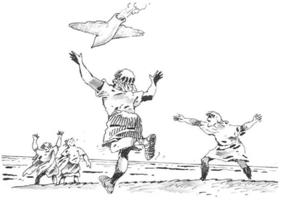
The first reported breakthrough work on autonomous mechanisms is attributed to Archytas from the city of Tarentum in South Italy, who was known as Archytas the Tarantine, also referred to as the Leonardo da Vinci of the Ancient World. He created the first UAV of all time in 425 B.C. by building a mechanical bird, a pigeon that could fly by moving its wings, getting energy from a mechanism in its stomach (see Figure 1.2). It is alleged that it flew about 200 meters before falling to the ground, once all its energy was used. The pigeon could not fly again [6], unless the mechanism was reset.
Figure 1.2 An artist's depiction of the flying pigeon, the first documented UAV in history. It is believed that it flew for 200 meters [5]
During the same era, the Chinese were the first to develop the idea of vertical flight. The earliest version of a top consisted of feathers at the end of a stick. The stick was spun between the hands to generate enough lift, before being released into free flight.
More than seventeen centuries later, the initial idea attributed to Archytas surfaced again: a similar ‘flying bird’, credited to some unknown engineer of the Renaissance, was documented (see Figure 1.3). It is not known whether this new design was based on Archytas’ idea; however, the concept was very similar.
Figure 1.3 A similar ‘flying bird’ with a mechanism in its stomach, attributed to an engineer during the Renaissance [5]

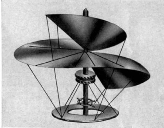
Leonardo da Vinci, in 1483, designed an aircraft capable of hovering, called an aerial crew or air gyroscope, as shown in Figure 1.4. It had a 5-meter diameter and the idea was to make the shaft turn and, if enough force was applied, the machine could spin and fly. This machine is considered by some experts to be the ancestor of today's helicopter [7, 8]. Da Vinci also devised a mechanical bird in 1508 that could flap its wings by means of a double crank mechanism as it descended along a cable.
Figure 1.4 Leonardo da Vinci's aerial crew (Hiller Aviation Museum [8])
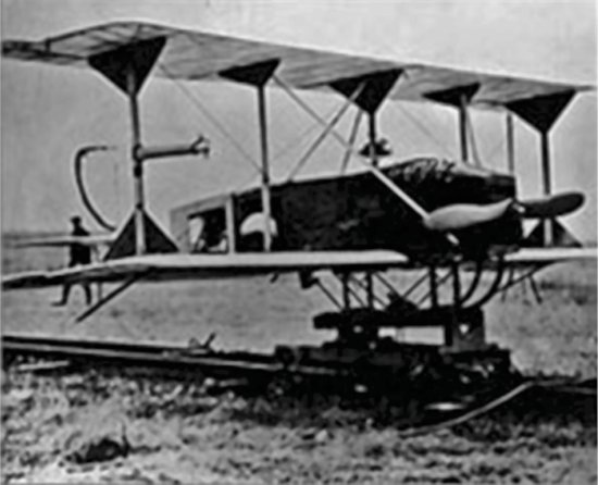
Many more flying machines were designed between 1860 and 1909, initially focusing on vertical take-off and landing aircraft because of the limitations of the steam-powered engines that were in use at the time. These machines led to the aircraft designs that are in use today. The first ‘modern’ UAV was manufactured in 1916 by the Americans Lawrence and Sperry [9]. It is shown in Figure 1.5. They developed a gyroscope to stabilize the body, in order to manufacture an autopilot. This is known as the beginning of ‘attitude control’, used for the automatic steering of an aircraft. They called their device the ‘aviation torpedo’ and Lawrence and Sperry actually flew it a distance that exceeded 30 miles.
Figure 1.5 The ‘aviation torpedo’ of Lawrence and Sperry [9]
The main drive behind aircraft development has always been the fast and safe transportation of people and cargo. Nevertheless, the military soon realized the potential benefits of unmanned aircraft and efforts to adapt flying machines to operate without a pilot onboard started. Such systems were initially unmanned ordinance delivery systems, what would now be referred to as ‘missiles’ or ‘smart bombs’. Another use for such systems was to operate as ‘drones’, to assist in the training of anti-aircraft gun operators.
Figure 1.6 Several variations of the Ryan Model 147 unmanned reconnaissance drone used in the 1960s and 1970s [5]
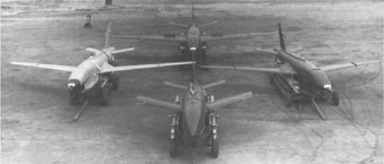
Probably the first unmanned aircraft that can withstand today's definition of UAS was the Ryan Model 147 series aircraft shown in Figure 1.6. It was based on a drone design and was used for reconnaissance missions by the USA over China, Vietnam and other countries in the 1960s and 1970s.
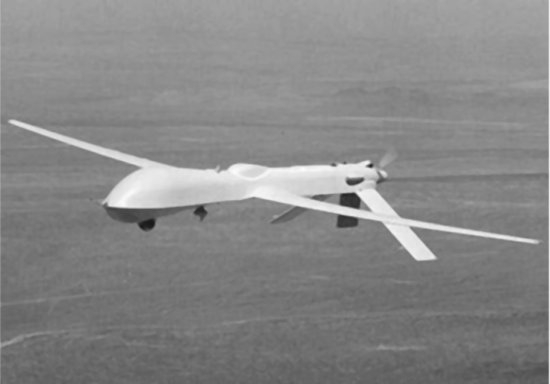
After the Vietnam War, the USA and Israel began to develop smaller and cheaper UAVs. These were small aircraft that adopted small engines such as those used in motorcycles or snowmobiles. They carried video cameras and transmitted images to the operator's location. It seems that the prototype of the present UAV can be found in this period. The USA put UAVs into practical use in the Gulf War in 1991, and UAVs for military applications developed quickly after this. The most famous UAV for military use is the Predator, which is shown in Figure 1.7.
Figure 1.7 The MQ-1 Predator built by General Atomics Aeronautical Systems Inc. [10]
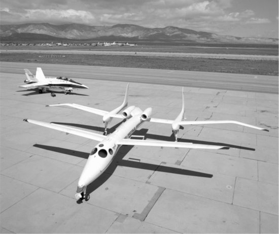
On the other hand, NASA is at the center of the research for civil use. The most typical example is the ERAST (Environmental Research Aircraft and Sensor Technology) project. It started in the 1990s, and was a synthetic research endeavor for a UAV that included the development of the technology needed to fly at high altitudes of up to 30,000 m, along with a prolonged flight technology, engine, sensor, etc. The aircraft developed in this project include Helios, Proteus, Altus, Pathfinder, etc., some of which are shown in Figures 1.8 and 1.9 [11]. These were designed to carry out environmental measurements.
Figure 1.8 The Helios UAV [11]
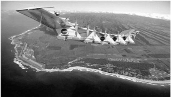
Figure 1.9 The Proteus by NASA [11]
1.3 UAV Classification
During recent decades, significant efforts have been devoted to increasing the flight endurance and payload of UAVs, resulting in various UAV configurations with different sizes, endurance levels and capabilities. This has led to attempts to explore new and somewhat unconventional configurations. Here, an attempt is made to classify UAVs according to their characteristics (aerodynamic configuration, size, etc.). Despite their diversity, UAV platforms typically fall into one of the following four categories:
Figure 1.10 Examples of fixed-wing UAVs
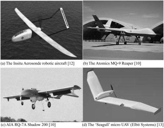
Figure 1.11 Examples of rotary-wing UAVs
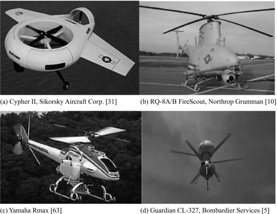
Figure 1.12 Examples of airship-design UAVs
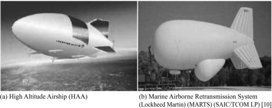
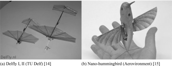
Figure 1.13 Examples of micro flapping-wing UAVs
- Fixed-wing UAVs, which refer to unmanned airplanes (with wings) that require a runway to take off and land, or catapult launching. These, generally, have long endurance and can fly at high cruising speeds (see Figure 1.10 for some examples).
- Rotary-wing UAVs, also called rotorcraft UAVs or vertical take-off and landing (VTOL) UAVs, which have the advantage of hovering capability and high maneuverability. These capabilities are useful for many robotic missions, especially in civilian applications. A rotorcraft UAV may have different configurations, with main and tail rotors (conventional helicopter), coaxial rotors, tandem rotors, multi-rotors, etc. (see Figure 1.11 for some examples).
- Blimps such as balloons and airships, which are lighter than air and have long endurance, fly at low speeds and generally are large in size (see Figure 1.12 for some examples).
- Flapping-wing UAVs, which have flexible and/or morphing small wings inspired by birds and flying insects (Figure 1.13).
- Hybrid configurations or convertible configurations, which can take off vertically and tilt their rotors or body and fly like airplanes, such as the Bell Eagle Eye UAV (Figure 1.14).
Figure 1.14 Examples of hybrid-configuration UAVs
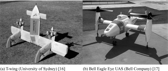
Figure 1.15 NASA Global Hawk HALE UAV (Northrop Grumman) [18]
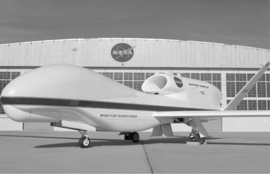
Figure 1.16 Examples of MALE UAVs
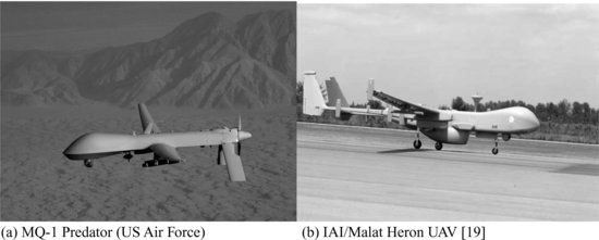
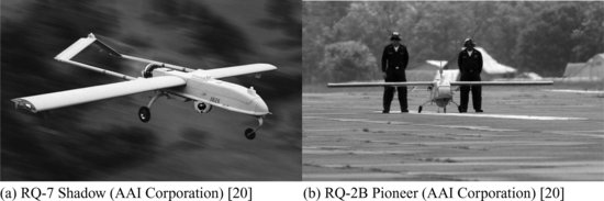
Figure 1.17 Examples of tactical UAVs
Another criterion used to differentiate between UAVs is size and endurance. The different categories used are [10]:
- High altitude long endurance (HALE) UAVs, as for example the Northrop Grumman Ryan's Global Hawks (65,000 ft altitude, 35 h flight time, 1900 lb payload) shown in Figure 1.15.
- Medium altitude long endurance (MALE) UAVs, as for example the General Atomics’ Predator (27,000 ft altitude, 30/40 h flight time, 450 lb payload) shown in Figure 1.16.
- Tactical UAVs such as the Hunter, Shadow 200 and Pioneer (15,000 ft altitude, 5/6 h flight time, 25 kg payload), see Figure 1.17.
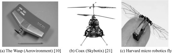
- Small and mini man-portable UAVs such as the Pointer/Raven (Aerovironment), Javelin (L-3 Communications/BAI) or Black Pack Mini (Mission Technologies), see Figure 1.18.
- Micro aerial vehicles (MAV): these have dimensions smaller than 15 cm and in the last few years have gained a lot of attention. They include the Black Widow manufactured by Aerovironment, the MicroStar from BAE and many new designs and concepts presented by several universities, such as the Entomopter (Georgia Institute of Technology), Micro Bat (California Institute of Technology) and MFI (Berkeley University), along with other designs from European research centers like MuFly, Coax, etc. (see Figure 1.19).
Figure 1.18 Examples of man-portable UAVs
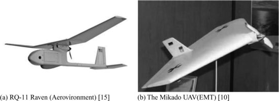
Figure 1.19 Examples of MAVs
1.4 UAV Applications
Currently, UAVs are being used primarily for military applications and the main investments are driven by future military scenarios. Most military unmanned aircraft systems are used for intelligence, surveillance, reconnaissance (ISR) and strikes. The main user is the US DoD, followed by the Israeli Military Forces. UAVs have been used in the recent conflicts over former Yugoslavia, Iraq, Afghanistan, Libya and elsewhere.
Figure 1.20 X-45 UCAV (Boeing Corporation) [31]

The next generation of UAVs will execute more complex missions, such as air combat, target detection, recognition and destruction, strike/suppression of an enemy's air defense, electronic attack, network node/communications relay, aerial delivery/resupply, anti-surface ship warfare, anti-submarine warfare, mine warfare, ship-to-objective maneuvers, offensive and defensive counter air and airlift. The trend is thus to replace manned missions, especially in ‘dull, dirty and dangerous’ tasks covering a significant part of warfare activity. The DoD goal is that by 2012–2013, one-third of the aircraft in the operational deep strike force should be unmanned [22]. The X-45 unmanned combat aerial vehicle (UCAV) (Figure 1.20), built by Boeing Corporation, incorporates the above-mentioned concept.
Nowadays, and after many years of development, UAS are reaching the critical point at which they could be applied in a civil/commercial scenario. Numerous UAS market forecasts portray a burgeoning future, including predictions of a $10.6B market by 2013 [23]. There are some corporations focusing on civil applications, for example two American organizations (Radio Technical Commission for Aeronautics (RTCA) and NASA) and one European organization (UAVNET), which have been applying research efforts in order to respond to the potential use of UAS for a variety of science and civil operational missions. Through a series of data-gathering workshops and studies, these organizations have developed some compendia [23--25] of potential UAS-based civil mission concepts and requirements. From these compendiums it is summarized that the potential civilian applications can be categorized into five groups [25]:
Figure 1.21 Environmental and earth science applications
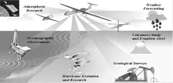
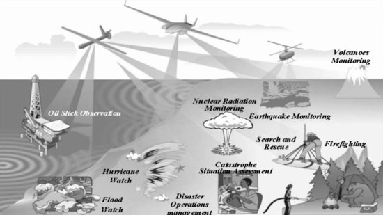
Figure 1.22 Emergency applications
- Environmental (or earth science) applications (Figure 1.21). These include remote environmental research (i.e., magnetic field measurement, ice thickness monitoring, etc.), atmospheric monitoring and pollution assessment (i.e., stratospheric pollution monitoring, CO2 flux and volcanic dust measurements, etc.), weather forecast, geological surveys (i.e., mapping of subsidence and mineral distribution, oil search, etc.).
- Emergency applications (Figure 1.22). These include firefighting, search and rescue, tsunami/flood watch, nuclear radiation monitoring and catastrophe situation awareness, humanitarian aid delivery, etc.
- Communications applications (Figure 1.23). Telecommunication relay services, cell phone transmissions or broadband communications are a few examples of communication applications.
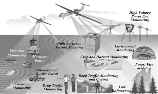
- Monitoring applications (Figure 1.24). These include homeland security (marine and international border patrol, coastal monitoring, law enforcement, etc.), crop and harvest monitoring, fire detection, infrastructure monitoring (oil/gas lines, high-voltage power lines, pipelines, etc.) and terrain mapping (forest mapping, remote sensing of urban areas, etc.).
- Commercial applications. These include aerial photography, precision agriculture–chemical spraying, transportation of goods and post, etc.
Figure 1.23 Communications applications
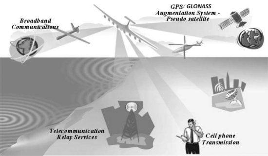
Figure 1.24 Monitoring applications
1.5 UAS Market Overview
Summarizing, UAS can offer major advantages when used for aerial surveillance, reconnaissance and inspection in complex and dangerous environments. Today, there are several companies developing and producing hundreds of UAV designs. Indeed, major defense contractors are involved in developing and producing UAVs (like Boeing, BAE Systems, Lockheed-Martin and EADS). At the same time, newer or smaller companies have also emerged with innovative technologies that make the market even more vibrant. US companies currently hold about 63–64% of the market share, while European companies account for less than 7% [27]. In 2005, some 32 nations were developing or manufacturing more than 250 models of UAV, and about 41 countries were operating more than 80 types of UAV, primarily for reconnaissance in military applications [10].
Several market studies [26--29] have predicted that the worldwide UAV market will expand significantly in the next decade. As stated in [26], over the next 4–5 years (until 2015), the UAV market in the USA will reach $16B, followed by Europe, which is spending about $2B. In the USA, for example, development budgets increased rapidly after 2001, as shown in Figure 1.25, and UAV research and development was given a powerful push [10]. On the other hand, the R&D budgets in Europe have increased slowly, as seen in Figure 1.26.
Figure 1.25 Annual funding profile by the US Department of Defense [10]
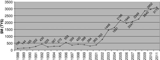
Figure 1.26 Annual funding profile in Europe [30]
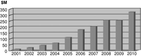
Figure 1.27 R&D and procurement costs forecast [29]
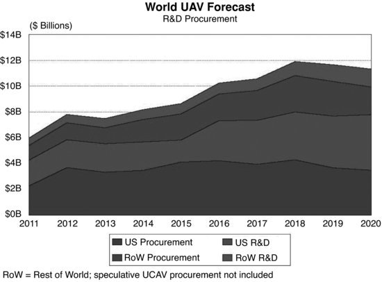
Other studies are predicting the annual expenditure to reach 2.3 billion by 2017 [28], or 11.3 billion by 2020 [29] (Figure 1.27). According to [29], the most significant catalyst to this market has been the enormous growth of interest in UAVs by the US military, tied to the general trend toward information warfare and net-centric systems. Teal Group expects the military applications to dominate the market and the sales of UAVs to follow recent patterns of high-tech arms procurement worldwide, with Asia representing the second largest market (about 18% of the worldwide total), followed by Europe. A civil market for UAVs is expected to emerge slowly over the next decade, starting first with government organizations requiring surveillance systems similar to military UAVs, such as coast guards, border patrol organizations and similar national security organizations. A commercial, non-governmental UAV market is expected to emerge much more slowly. The significant differences between reports are caused by the fact that the UAV is an immature market and the lack of specific requirements, especially in the civil sector, makes forecasts problematic.
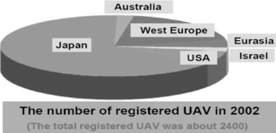
The true potential of a civil market for UAVs can be extracted by the example of Japan, where the incorporation of small unmanned helicopters used for agriculture–chemical spraying has increased tremendously the number of registered UAVs, as shown in Figure 1.28 [30].
Figure 1.28 Number of registered UAVs per region [30]
As indicated in [25] and for a specific application (pipeline monitoring), the main drivers for UAV civil market expansion are:
Figure 1.29 Strengths and weaknesses of UAVs [25]
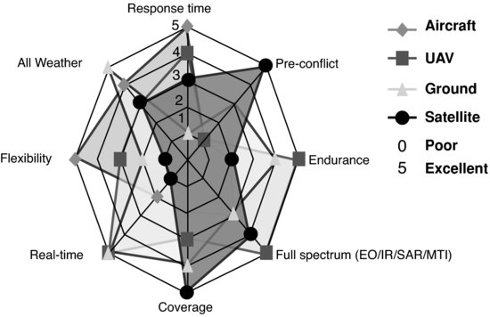
- Increased capabilities (especially endurance, real-time deployment and full spectrum coverage) when compared with other technologies (Figure 1.29).
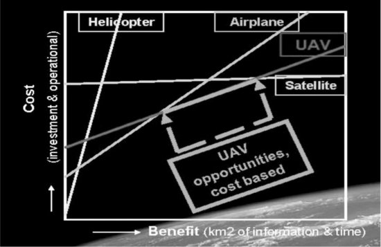
- Cost advantage (Figure 1.30).
- Technology maturation (due to military applications).
- New applications.
On the other hand, there are significant barriers to the emergence of a civil market for UAVs, both of technological and regulatory nature.
Figure 1.30 Cost/benefit of different technologies for pipeline monitoring application2[25]
1.6 UAS Future Challenges
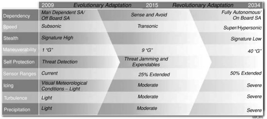
The US DoD is the main contributor to the future evolution of UAS for military use, being the main R&D funder. The future requirements for military UAS, along with lessons learned and current issues, are included in the Unmanned Systems Integrated Roadmap reports published by the DoD [1,4,10,22]. According to these reports, the performance envelope for unmanned systems must keep pace with the demands of the missions that will be expected of these types of system, thus performance attributes associated with unmanned systems must evolve significantly. Figures 1.31–1.33 provide a depiction of the projected evolution of key performance attributes unmanned systems must exhibit in order to enable the projected missions and tasks.
Figure 1.31 Trends in UAS autonomy [10]
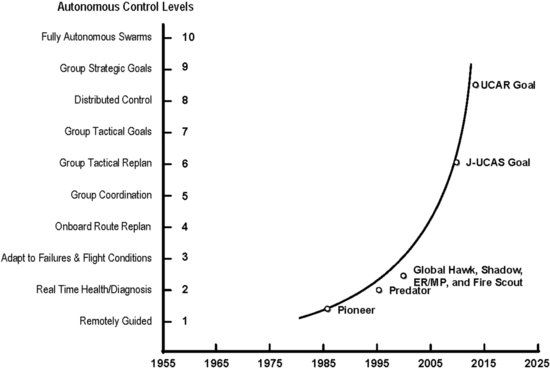
Figure 1.32 Performance envelope evolution (common to all robotic systems) [22]
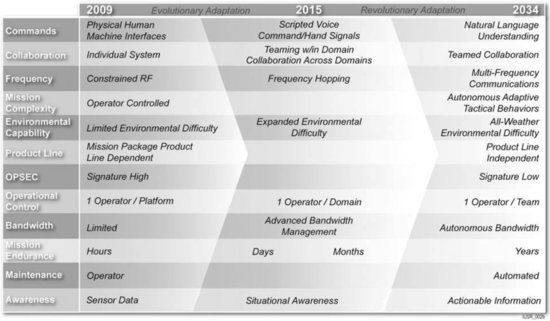
Figure 1.33 Performance envelope evolution (UAS only) [22]
- First and foremost, the level of autonomy should continue to progress from today's fairly high level of human control/intervention to a high level of autonomous tactical behavior that enables more timely and informed human oversight (Figure 1.31). Thus, today's remotely controlled systems will turn to highly autonomous UASs (or groups of UASs).
- The focus of human interface with the machine should evolve from today's current physical interfaces such as joysticks, touch screens, etc. to interaction such as hand signals and, ultimately, to natural language understanding in order to be tasked for missions.
- Similarly, as the need to communicate between humans and unmanned systems will always be a requirement, the spectrum in which unmanned systems communicate must evolve past radio frequencies and exhibit an agility to hop around in the spectrum to ensure robust, secure communications. Today, minimal emphasis has been placed on operational security, thus most UAS exhibit fairly easily detectable acoustic, thermal, visual and communication signatures. In the future, unmanned systems will be required to carry out missions in a covert manner, thus low observable and signature management attributes will be desirable.
- Moreover, mission duration should increase. Today, mission endurance is measured in hours. In the future, it will be desirable for unmanned systems to conduct their missions in durations measured in days, weeks, months and possibly years. This is a key desirable attribute, as manned tasks are always constrained by the human body's need for food and sleep.
- Another key desirable feature will be mission equipment packages that can be interchanged between platforms and potentially even across domains. Today, most payloads are designed for integration with a single platform. By providing interchangeability across platforms and domains, commanders will be afforded a great flexibility in terms of available options for conducting specific missions in specific types of circumstance. Finally, performance should evolve from today's controller-to-platform ratio of many to one or, at best, one to one to a single controller being able to monitor multiple unmanned systems performing across domains as collaborating teams.
- Speed and maneuverability could also increase well beyond that of manned systems, where limitations are imposed by human physical limits. The human body can only sustain 9g of acceleration, whereas technology is the only limiting factor for unmanned systems being able to execute maneuvers that create forces reaching or exceeding 40g acceleration.
- The ability to operate in different weather profiles (all weather) and high turbulence will be required.
- Situational awareness is also a significant issue. In the air, UAS will need the ability to sense objects and avoid them, the biggest challenge being small objects moving at high speeds. The situation awareness capability is closely related to the availability of increased range sensors and highly intelligent processing algorithms.
- Finally, survivability, maintainability and reliability issues should be resolved if longer mission durations are to be accomplished. Minimally, unmanned systems must be reliable enough to keep up with mission endurance times.
Although the above guidelines apply for military UAS, a lot of them are common to civil applications as well (especially civil governmental applications). A unified roadmap has not yet been published, but there are general guidelines (for example, [23--25]). The major barrier to civil UAS expansion has been identified as their restricted operation in a segregated part of the airspace. This was the topic of investigation of a £62M UK-led project called ASTRAEA [61], the second phase of which is still under development. Virtually all of the civil applications discussed will require access to either a country's specific national airspace (NAS) and/or foreign airspace at some point in the flight pattern. Even missions intended for remote areas require access to get the aircraft to the area. This has not (for the time being) been the case for military use of UAVs that are deployed in conflict areas, where most civil aviation is ceased. However, civil use requires UAS to be operated in close proximity to human activity and to be fully integrated into the air traffic system (ATS). A similar interest has been expressed by military users. FAA (respectively CAA in the UK and EUROCAE and EUROCONTROL in Europe) standards are only now beginning to emerge for routine UAV operations in US airspace. This is also true worldwide with the exceptions of the UK (CAP722), Israel and South Africa, which have established UAV operating rules through their civil aviation administration. Up to now, in all the countries that have incorporated operational guidelines that allow limited operations in their respective NAS, UAS flight is segregated from the rest of the air traffic with the use of NOTAMs [31]. Even in these cases, there have been complaints by Israeli aviation over the interference experienced due to UAV operations. In 2006, there was an incident near Tel Aviv airport where a UAV came close to a passenger aircraft [29]. In Europe, the EASA issued a call in early 2006 for the formation of a new organization to coordinate the use of UAVs in Europe. The aim is to permit ‘normalized’ UAV flights in non-segregated airspace by the beginning of the next decade. In addition, efforts are underway to unify European standards with other standards such as those being developed in the USA by RTCA and ASTM (American Society of Testing and Materials), with EUROCAE (European Organization for Civilian Aviation Equipment) considering the development of mirror standards with FAA cooperation.
Closely related to the airspace access are a number of regulatory and technological issues similar to the ones considered for military UAS. These issues must be addressed before UAS are authorized for unrestricted and continuous access to the airspace. These issues are:
- The lack of prescriptive standards and regulations governing the routine operation of UAS in the civilian airspace system. The collaboration of air traffic controllers with UAS operators needs to be accurately defined. Also, automated separation assurance algorithms for seamless and safe operation of UAS in high-density operating environments are needed. As UAS are becoming more and more autonomous, allocation of roles and responsibilities between automation and humans in identifying conflicts and providing separation assurance is vital. Regulations are also needed for the certification of UAS operations and maintenance activities.
- Secure and reliable communications have to be established both between the UA and the control station and/or the ATS control station and the UAS. Minimum performance standards to be met by the communications and control system of the UAS need to be established.
- Reliability and airworthiness of UA is another important issue. Currently, there are strict regulations for the reliability of manned aircraft. The aircraft control system, for example, has been identified as a ‘safety critical’ system and as such it must be extremely reliable according to FAA regulation parts 23, 25 and 27. The probability of system failure should be less than 10−19 per flight hour. Moreover, other quality requirements are on top of the probabilistic assessment (i.e., a catastrophic consequence must not be due to a single failure – surface or pilot input jam). In order to meet requirements like the above, aerospace industry uses a combination of fault avoidance and removal, fault tolerance and fault detection and diagnosis. Every industry has developed its own methods (like the V-cycle implemented by Airbus [32]). Generally, increased reliability is accomplished by a combination of:
- A stringent development process both for hardware and software, where reliability analysis, failure mode and effect analysis, risk classification, etc. are used to dynamically define equipment specifications.
- Hardware (and software) redundancy (the use of triple or quadruple sensors and other equipment in safety critical systems is common to all aircraft [33]).
- Dissimilarity and installation segregation of critical components.
According to the JAA/EUROCONTROL UAS Task Force, as well as the EASA, one of the guiding principles for UAS regulation should be the equivalence, or ELOS (equivalent level of safety) and based on that, they assert the following [31,34]:
Regulatory airworthiness standards should be set to be no less demanding than those currently applied to comparable manned aircraft nor should they penalize UAS systems by requiring compliance with higher standards simply because technology permits.
Since most UAS are based on military or general aviation aircraft, the increased risk stems from the separation of the pilot from the cockpit and the level of automation introduced, rather than the design and construction of the airframe of the UA itself. However, unlike manned aircraft, UAVs impose additional constraints in the above process due to limited payload and weight restrictions that prohibit the use of physical (hardware) redundancy in order to increase system reliability. Moreover, the cost involved in the use of high-reliability equipment could restrain the cost benefit of UAVs in civil applications. It is, thus, necessary to develop reliable algorithms for fault detection and isolation using the concept of analytical (or software) redundancy combined with algorithms that make it possible to control the vehicle in faulty situations (fault-tolerant control concept). In specific cases of faults (i.e., lost communication), the means to terminate the flight and/or recover the vehicle without causing an accident is extremely important, especially if the UAV is used in close proximity to humans. The development of standardization procedures for airworthiness qualification is difficult for UAVs due to their immense diversity and roles. These standards are now beginning to emerge based on failure data obtained from military experience. A discussion of ELOS requirements for UAVs can be found in [31].
- Another major technological issue connected to airspace access is the need for ‘sense and avoid’ systems on UAVs operating in controlled airspace [35]. This system will allow UAVs to ‘see’ or detect other aircraft (piloted or uninhabited) and avoid them. The technology for this system is decomposed into two elements: ‘see’ and ‘avoid’. The ‘see’ portion involves the detection of intruding aircraft through some type of sensor. The ‘avoid’ portion involves predicting if the intruding aircraft poses a danger and what course of action should be taken through a decision-making (software) algorithm. For sensors, the priority should be to detect aircraft at sufficient distance so that emergency maneuvering can be avoided. The first step in this development will be to implement a cooperative sensor for collision avoidance. Under the cooperative category, aircraft will have transponders or data links notifying other aircraft of their position. The second and more difficult portion is non-cooperative detection. In this case, the ‘other’ aircraft does not share its position (as would be the case for many general aviation aircraft) and must be detected with radar or optics. For avoidance, sensor information must be used to predict future positions of host (ownship) and intruder aircraft to determine collision potential. If a collision potential exists, a safe escape trajectory must be derived and automatically executed if the operator has insufficient time to react. The ‘sense and avoid’ concept is a complicated issue requiring both the design and development of lightweight long-range sensors and the algorithms required for information processing and reliable navigation. This issue is addressed in detail in the other chapters of this book.
Several other considerations for the future capabilities of UAVs have been introduced, focusing on civil applications [23]:
- A high level of autonomy in the mission management function is required to take advantage of using a UAV platform to support the missions. Less direct human interaction in flying the UAV allows less on-station personnel, less on-station support infrastructure, and one operator to monitor several vehicles at a given time. These goals must be balanced with the requirement for the operator and vehicle to respond to air traffic control in a timely manner. The mission management system should also allow redirection of the mission (including activating the contingency management system) from the ground. This would be useful, especially for dynamically changing operation environments which cannot be adequately foreseen at mission initiation. It is envisioned that the human interaction with the onboard mission manager system will occur at the mission objectives level.
- Just like military UAS, the use of swarms of UAVs is going to be necessary for the cost-effective application of UAS in many civil applications, especially those involved with monitoring.
- Longer durability and robustness to weather conditions and turbulence will also be a requirement depending on application.
1.7 Fault Tolerance for UAS
As described above, the increase of reliability and survivability is necessary for future UAS both for meeting airworthiness specifications and for cost-effective operation and longer missions. Both of these goals can be achieved in the context of fault tolerance. In this section the major concepts of fault tolerance for UAS are introduced with an overview of existing methods.
Incident analysis of UAS (Figure 1.34) has clearly shown that the major part of the accidents (nearly 60%) involve UA failures (propulsion and flight control), followed by communication failures and human factors [10]. With the removal of the pilot, the rationale for including the level of redundancy or for using man-rated components considered crucial for his/her safety, can go undefended in UA design reviews, and may be sacrificed for affordability. While this rationale may be acceptable for military missions, it cannot be adopted for civil UAS. On the other hand, aircraft reliability and cost are closely coupled, and unmanned aircraft are widely expected to cost less than their manned counterparts, creating a potential conflict in customer expectations. Less redundancy and lower-quality components, while making UA even cheaper to produce, mean that they become more prone to in-flight loss and more dependent on maintenance.
Figure 1.34 Failure sources for UAVs based on (upper) US military (194,000 flight hours) and (lower) IAI military (100,000 flight hours) [10]
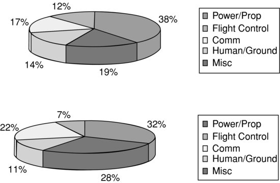
There are two widely accepted methods used in aircraft design to increase reliability: the use of higher-reliability components and the increase of hardware redundancy in the system. However, neither of them can be applied directly in the case of UAs because of additional cost and weight/payload constraints. Additional constraints also arise from faster dynamics and increased modeling uncertainty of UAS. Moreover, the reduced situation awareness of the operator located away from the cockpit makes the problem of failure handling particularly difficult for UAS. It seems that this technological gap can be covered by the use of analytical redundancy (software redundancy) techniques for fault detection and identification (FDI) and the incorporation of fault-tolerant control (FTC) techniques coupled with increased autonomy. FDI/FTC has been an active area of research for many years and many methods exist in the literature ([36, 37] provide thorough overviews). Some of these methods have been applied to aerospace systems, especially military [38] and large transport aircraft [33].
The fault-tolerant control can, generally, be classified as passive and active. In passive techniques the controller is designed to tolerate not only uncertainty but also a class of faults leading to conservative designs while in the active approach, the controller relies heavily on an FDI module and the information it provides. The classification of some recent and popular techniques to design fault-tolerant flight control systems along with example books/papers is shown in Figure 1.35.
Figure 1.35 Classification of fault-tolerant flight control methods with recent examples
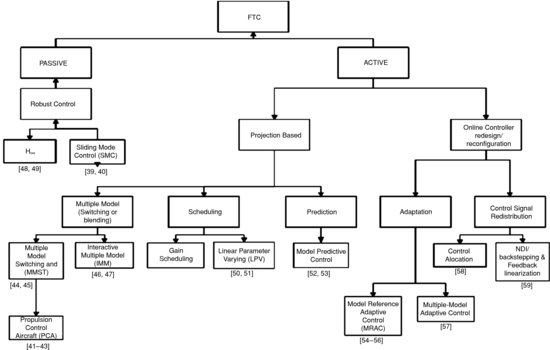
Table 1.1 Comparison of different methods for FTC (Information partially taken from [33])

Some of the methods described above were applied on a detailed simulation of the Boeing 747-100/200 aircraft [33] as part of the Group of Aeronautical Research and Technology in Europe (GARTEUR) program. Table 1.1 summarizes the major results of comparison of the several methods found in the literature.
Despite the large variety of methods, FDI/FTC techniques are not widely adopted in the aerospace industry and only some space systems have incorporated these techniques in the final design. The reason for this is the immaturity of the methods, especially for non-linear systems, as well as the complexity of the designs and the possibility of high levels of false alarms in case of large modeling uncertainties and/or disturbances. What's more, the high risk of human lives in manned aircraft, along with the mature and tested alternative of hardware redundancy, makes the incorporation of the above methods less attractive.
This is not the case for UAs, where the reduced payload prohibits (or restricts) the use of existing hardware redundancy schemes. The faults that an FDI/FTC system must detect and compensate are similar to those of a manned aircraft (Table 1.2), however, the specifications that an FDI/FTC system must meet for a UA are much more strict. The design of FDI/FTC algorithms for UAs must focus on robustness to modeling uncertainties, simple design and low complexity. For small UAS with very limited computational power, passive techniques seem especially attractive due to the avoidance of the FDI module. In any case, the comparison of many different techniques to highlight the pros and cons for every category of platform is necessary.
In order to reach these goals, there is a need to develop realistic benchmark models to assist the research. These models should include actuator and sensor dynamics as well as modeling uncertainties and disturbances. Also, issues like fault-tolerant navigation and decision making under health state uncertainty must be addressed as well.
Table 1.2 Aircraft/UA failure modes [60]
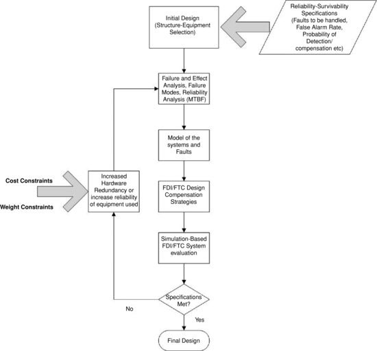
Finally, it should be pointed out that the FDI/FTC methods found in the literature cannot provide a complete solution to the reliability improvement problem for UAs. These methods focus on increasing fault tolerance for a given degree of redundancy and, thus, they are limited to the degree of redundancy selected. On the other hand, reliability improvement is a multi-objective optimization problem that involves reliability specifications, redundancy, fault-tolerance evaluation and cost. A schematic representation of a possible design cycle is shown in Figure 1.36.
Figure 1.36 Design cycle of UAS for reliability improvement
References
1. Unmanned Systems Roadmap 2002–2027, Report of the Office of the Secretary of Defense, DoD, USA, 2002.
2. STANAG 4671 – Unmanned Aerial Vehicle Systems Airworthiness Requirements (USAR), Joint Capability Group on Unmanned Aerial Vehicles (Draft), NATO Naval Armaments Group, 2007.
3. Unmanned aircraft systems operations in the U.S. national airspace system, Federal Aviation Administration, Interim Operational Approval Guidance 08-01, 2008.
4. Unmanned Systems Roadmap 2007–2032, Report of the Office of the Secretary of Defense, DoD, USA, 2007.
5. Castillo, P., Lorenzo, R., and Dzul, A.E. Modeling and Control of Mini-Flying Machines, Springer, 2005.
6. Guedj, D. Le Théorème du Perroquet, Editions du Seuil, 1998.
7. Helicopter History Site, History of helicopters, June 2004. Available at http://www.hiller.org (last accessed 27/4/2011).
8. Hiller Aviation Museum. Available at http://www.hiller.org (last accessed 27/4/2011).
9. Stoff, J. Historic Aircraft and Spacecraft in the Cradle of Aviation Museum, Dover Publications, 2001.
10. Unmanned Systems Roadmap 2005–2030, Report of the Office of the Secretary of Defense, DoD, USA, 2005.
11. http://www.dfrc.nasa.gov (last accessed 27/4/2011).
12. http://www.aerosonde.com (last accessed 17/4/2011).
13. http://www.unmanned.co.uk/keyword/elbit/ (last accessed 28/4/2011).
14. http://www.delfly.nl/ (2/4/2011).
15. http://www.avinc.com/media_gallery/images/uas/ (last accessed 26/4/2011).
16. http://sydney.edu.au/engineering/aeromech/uav/twing/ (last accessed 28/4/2011).
17. http://www.bellhelicopter.com/en/aircraft/military/bellEagleEye.cfm (last accessed 28/4/2011).
18. http://www.NASA.org (last accessed 29/4/2011).
19. http://www.iai.co.il/ (last accessed 18/4/2011).
20. http://www.aaicorp.com/ (last accessed 20/4/2011).
21. http://www.skybotix.com/ (last accessed 24/4/2011).
22. Unmanned Systems Roadmap 2009–2034, Report of the Office of the Secretary of Defense, DoD, USA, 2009.
23. Civil UAV capability assessment, NASA, 2006. Interim Report, http://www.nasa.gov/centers/dryden/research/civuav/index.html (last accessed 21/3/2011).
24. http://www.rtca.org/ (19/3/2011).
25. http://www.uavnet.org/ (29/4/2011).
26. The unmanned aerial vehicles (UAV) market 2009–2019, Visiongain, 2009.
27. Dickerson, L. ‘UAV on the rise’, Aviation Week Space Technology, Aerospace Source Book, 166(3), 2007.
28. http://www.researchandmarkets.com/research/afdcf8/homeland_security_and_commercial_unmanned (last accessed 28/4/2011).
29. Zaloga, S.J., Rockwell, D., and Finnegan, P. ‘World Unmanned Aerial Vehicle Systems: Market Profile and Forecasts’, 2011 edition, Teal Group Corporation, 2011.
30. Nonami, K., Kendoul, F., Suzuki, S., Wang, W., and Nakazawa, D. Autonomous Flying Robots, Springer Science and Business Media, 2010.
31. Dalamagidis, K., Valavanis, K., and Piegl, L.A. On Integrating Unmanned Aircraft Systems into the National Airspace, Springer Science and Business Media, 2009.
32. Goupil, P. ‘Airbus state of the art and practices on FDI and FTC’, 7th IFAC Symposium on Fault Detection, Supervision and Safety of Technical Processes, Barcelona, Spain, 30 June–3 July, pp. 564–572, 2009.
33. Edwards, C., Lombaerts, T., and Smaili, H. Fault Tolerant Flight Control – A Benchmark Challenge, Spinger-Verlag, 2010.
34. European Aviation Safety Agency (EASA), A-NPA, No. 16/2005, Policy for unmanned aerial vehicle (UAV) certification, 2005.
35. Davis, B. ‘UAS in the national airspace: the NTSB takes a look’, Unmanned Systems, 26(6):40–41, 2008.
36. Zhang, Y. and Jiang, J. ‘Bibliographical review on reconfigurable fault-tolerant control systems’, Annual Reviews in Control, 32:229–252, 2008.
37. Venkatasubramanian, K. et al. ‘A review of process fault detection and diagnosis Part I (Quantitative model-based methods), Part II (Qualitative models and search strategies, Part III (Process history based methods)’, Computers and Chemical Engineering, 27:293–346, 2003.
38. Urnes, J., Yeager, R., and Steward, J. ‘Flight demonstration of the self-repairing flight control system in a NASA F-15 aircraft’, National Aerospace Electronics Conference, Dayton, OH, USA, May 1990. Report 90CH2881-1.
39. Hess, R.A. and Wells, S.R. ‘Sliding mode control applied to reconfigurable flight control design’, AIAA Journal of Guidance, Control and Dynamics, 26:452–462, 2003.
40. Alwi, H. and Edwards, C. ‘Fault detection and fault tolerant control of a civil aircraft using a sliding-mode-based scheme’, IEEE Transactions on Control Systems Technology, 16(3):499–510, 2008.
41. Harefors, M. and Bates, D.G. ‘Integrated propulsion-based flight control system design for a civil transport aircraft’, Proceedings of the 2002 IEEE International Conference on Control Applications, pp. 132–137, 2002.
42. Burcham, F.W., Fullerton, C.G., and Maine, T.A. ‘Manual manipulation of engine throttles for emergency flight control’, Technical Report NASA/TM-2004-212045, NASA, 2004.
43. Tucker, T. ‘Touchdown: the development of propulsion controlled aircraft at NASA Dryden. Monographs in Aerospace History, 1999.
44. Boskovic, J.D. and Mehra, R.K. ‘A multiple-model-based reconfigurable flight control system design’, Proceedings of the 37th IEEE Conference on Decision and Control, Tampa, FL, December, pp. 4503–4508, 1998.
45. Aravena, J., Zhou, K., Li, X.R., and Chowdhury, F. ‘Fault tolerant safe flight controller bank’, Proceedings of the IFAC Symposium SAFEPROCESS ’06, Beijing, pp. 8908–8912, 2006.
46. Rago, C., Prasanth, R., Mehra, R.K., and Fortenbaugh, R. ‘Failure detection and identification and fault tolerant control using the IMM-KF with applications to the Eagle-Eye UAV’, Proceedings of the 37th IEEE Conference on Decision and Control, Tampa, FL, December, pp. 4503–4508, 1998.
47. Zhang, Y. and Jiang, J. ‘Integrated active fault-tolerant control using IMM approach’, IEEE Transactions on Aerospace and Electronic Systems, 37:1221–1235, 2001.
48. Zhou, K. and Ren, Z. ‘A new controller architecture for high performance, robust and fault tolerant control’, IEEE Transactions on Automatic Control, 46:1613–1618, 2008.
49. Ye, S., Zhang, Y., Li, Y., Wang, X., and Rabbath, C.-A. ‘Robust fault-tolerant tracking control with application to flight control systems with uncertainties’, Proceedings of the 10th IASTED International Conference on Control and Applications, 2008.
50. Shin, J.-Y. and Gregory, I. ‘Robust gain-scheduled fault tolerant control for a transport aircraft’, Proceedings of the 16th IEEE Conference on Control Applications (CCA 2007), 1–3 October 2007.
51. Ganguili, S., Marcos, A., and Balas, G.J. ‘Reconfigurable LPV control design for Boeing 747-100/200 longitudinal axis’, Proceedings of the American Control Conference, pp. 3612–3617, 2002.
52. Maciejowski, J.M. and Jones, C.N. ‘MPC fault-tolerant control case study: flight 1862’, Proceedings of the IFAC Symposium SAFEPROCESS ‘03, Washington, DC, pp. 119–124, 2003.
53. Campell, M.E., Lee, J.W., Scholte, E. and Rathbun, D. ‘Simulation and flight test of autonomous aircraft estimation, planning and control algorithms’, AIAA Journal of Guidance, Control and Dynamics, 30(6):1597–1609, 2007.
54. Shin, Y., Calise, A.J., and Johnson, M.D. ‘Adaptive control of advanced fighter aircraft in nonlinear flight regimes’, AIAA Journal of Guidance, Control and Dynamics, 31(5):1464–1477, 2008.
55. Tao, G., Chen, S., Tang, X., and Joshi, S.M. Adaptive Control of Systems with Actuator Failures, Springer-Verlag, 2004.
56. Shore, D. and Bodson, M. ‘Flight testing of a reconfigurable control system on an unmanned aircraft’, AIAA Journal of Guidance, Control and Dynamics, 28(4):698–707, 2005.
57. Fekri, S., Athans, M., and Pascoal, A. ‘Issues, progress and new results in robust adaptive control’, International Journal of Adaptive Control and Signal Processing, 20(10):519–579, 2006.
58. Ducard, G.J.J. Fault-tolerant Flight Control and Guidance Systems – Practical Methods for Small UAVs, Springer-Verlag, 2009.
59. Lombaerts, T.J.J., Huisman, H.O., Chu, Q.P., Mulder, J.A., and Joosten, D.A. ‘Flight control reconfiguration based on online physical model identification and nonlinear dynamic inversion’, Proceedings of the AIAA Guidance, Navigation and Control Conference,18–21 August, Honolulu, HI, 2008. AIAA 2008-7435, pp. 1–24.
60. Jones, C.N. Reconfigurable Flight Control – First Year Report, Control Group, Department of Engineering, University of Cambridge, 2005.
61. http://www.projectastraea.co.uk/ (last accessed 27/4/2011).
62. ‘Civil UAV capabilities assessment’, Interim Status Report, NASA, 2006.
63. http://www.barnardmicrosystems.com/L4E_rmax.htm (27/4/2011).
1. The characterization reusable is used to differentiate unmanned aircraft from guided weapons and other munitions delivery systems.
2. The benefit can be expressed by the area coverage of the sensors as a function of time (usually the quantity km2/h is used). Since this is a monitoring task, this area coverage is strongly connected with the information that can be gathered by the sensors. Thus a satellite has a big initial cost (especially due to investment costs but due to the high coverage capability (in km2/h) of its sensors, the slope of the curve is very small. At the same time a UAV has higher investment cost compared to an aircraft but a lower operational cost as a function of area coverage per hour of operation (smaller slope). Sometimes the benefit is expressed as useful payload × endurance (hours of flight).