CHAPTER 4
Basic Concepts for Defense Frameworks
The focus of this chapter is on the details of the Department of Defense Architecture Framework (DoDAF) and related defense frameworks. We use the DoDAF as the basis for our examples in both Parts II and III of this book. We chose the DoDAF for these examples because it is one of the oldest frameworks (only the Zachman Framework is older), its views are compatible with the TOGAF and form a subset of the Federal Enterprise Architecture Framework Version 2 (FEAF2) views, and it is the basis for many other defense frameworks.
There are many reasons why military organizations have tried to unify architectures through the definition of overarching architecture frameworks. Defense architecture frameworks are specified in general terms that enable them to be equally easily applied to developing weapons systems as to developing force structures and military missions and operations during wartime and peacetime. The need for coalition partners to interoperate and collaborate during coalition operations also requires that military partners have comparatively consistent, interoperable and well-documented architectures. The need for joint operations requires that the U.S. Navy, U.S. Army, U.S. Air Force, U.S. Marine Corps, and the U.S. Coast Guard all have compatible architectures. The primary purpose of defense architecture frameworks is to provide a common format and semantics for comparison, aggregation, and analysis of multiple architectures. With a common framework, classes of complex problems in a theater or on the battlefield such as joint asset visibility, joint mission threads, common operating picture, and others can be tackled by federating multiple architectures during the planning, acquisition, and resourcing phase to ensure that collaboration, interoperability, single operating picture, and unity of actions are accomplished under critical war-fighting conditions. One of the most important needs met by the DoDAF was an integrated view of architecture elements through many views that share subsets of the same architecture elements. The requirement of an integrated dictionary to be provided for every architecture presses out redundancy and ensures that integration is built into the architecture from the very beginning.
Work on what became the DoDAF started in the mid-1990s, as DoD’s Intelligence, Surveillance, and Reconnaissance (ISR) community struggled with trying to compare the architectures proposed by various contractors in response to requests for proposals (RFPs). The DoD as a whole was also struggling with interoperability issues for various processes and systems as it moved toward integrated task force strategies, which required the military services to work together. The DoDAF was designed to provide a common language for describing architectures and provided a flexible set of basic building blocks—that is, views—for telling the story of each architecture. The DoDAF provided a necessary basis for comparing architectures and for identifying critical interfaces.
Other defense organizations adopted and refined the DoDAF into their own frameworks. Examples of related defense frameworks are the United Kingdom’s Ministry of Defense Architecture Framework (MODAF), the Department of National Defense/Canadian Armed Forces Architecture Framework (DNDAF), the Australian Defense Architecture Framework (DAF), and the North Atlantic Treaty Organization (NATO) Architecture Framework (NAF), to name a few. In addition, the DoDAF views have been the basis for multiple U.S. federal agency architecture frameworks that have adopted the approach, viewpoints, and views as an integrated way of architecting. Extensions first developed in the MODAF have been integrated back into the DoDAF. Additional features developed in these related defense frameworks will undoubtedly be integrated back into DoDAF as it continues to evolve. Efforts are currently underway to specify a unified architecture framework ontology based on these defense architecture frameworks with assistance from standards bodies such as the Object Management Group (OMG).
We address the DoDAF concepts in the same order that generic enterprise architecture concepts were introduced in Chapter 1.
Levels of Enterprise
There are three basic levels of enterprise architecture usually used in DoDAF: Enterprise, Segment, and Solution. These levels are illustrated in Figure 4-1.

Figure 4-1 Levels of enterprise architectures
Enterprise Level architectures are used to support strategic decision-making for the enterprise. Segment Level architectures are used to manage coherent sets of related capabilities or business services to ensure coordination and interoperability of related business processes, systems, and data. Solution Level architectures are used to support and manage business process and related system development and acquisition efforts. The Solution Level includes the concepts of System of Systems (SoS) and Family of Systems (FoS). (SoS and FoS are defined in the upcoming “Solution Level” section.) We will examine each of these levels in this chapter.
Enterprise Level
The Enterprise Level includes architectures of enterprises with top-level strategic plans, goals, and objectives as well as multiple projects and a portfolio of IT investments to manage. At the Enterprise Level, management includes investment or project selection, control, and evaluation (as described in Chapter 10). The goal of an Enterprise Level architecture is to provide traceability from the enterprise strategic vision, goals, and objectives to the capabilities needed to achieve those objectives, to the projects (and their managing organizations) that implement those capabilities and to the organizations that use the capabilities. Phasing and timelines are key parts of this traceability.
Defense enterprises undertake complex, large multiyear acquisition programs from aircrafts and ships to worldwide software applications. These applications are deployed across thousands of personnel and require design constraints for security, survivability, performance, scalability, and deployability in austere environments. Much of this material is durable and has a service life of many years. (For example, a typical airframe may be used for more than 40 years with periodic upgrades.) By focusing on the capability needed rather than the specific solution requirement of the day, planners are able to architect these types of items to remain useful over their expected life-times. By applying a program-driven strategy for acquisition, military senior leaders are able to track the health of the acquisition through various milestones. The enterprise architecture aligns the capability requirements against the portfolio of programs that acquire the capability.
Here some example questions or issues that an Enterprise Level architecture might address:
• How do the business functions or capabilities relate to the enterprise’s strategy and goals?
• Are there dependencies among the capabilities or business functions?
• How will business function or capability performance be measured?
• When will the capabilities or business functions be implemented and what projects will provide them?
• What organizations will use the capabilities or business functions?
• What organizations are in charge of which projects?
• What are the timelines for the projects and what are the dependencies among them?
An example of Enterprise Level architecture is outlined for the RMN Airport Case Study in Chapter 5.
When an enterprise is so large that a single architecture is impractical, a Federated Architecture approach may be used. A Federated Architecture for an enterprise is made up of an integratable set of independently developed lower-level architectures. The set of lower-level architectures may be a set of Segment Level architectures together with corresponding Solution Level architectures, or a set of domain architectures, each oriented toward an architectural domain such as business, data, application, and technology. The enterprise has to provide sufficient guidance, such as enterprise-level reference models (described in Chapter 1), to ensure that the lower-level architectures use consistent terminology and can be integrated. The reference models most often used in conjunction with the DoDAF in the U.S. are the Federal Enterprise Architecture (FEA) reference models discussed in Chapter 23.
Another type of notional architecture used by defense organizations (especially in the infrastructure and technology area) is reference architecture. A reference architecture “is an authoritative source of information about a specific subject area that guides and constrains the instantiations of multiple architectures and solutions.” [OASD 2010] With the formulation of the DoDAF, it was possible to articulate notional architectures that serve as starting blueprints for specific enterprises to implement their own instances and variations using a common language, architecting paradigm, and suggested approach. Following are some of the reference architectures that have been developed using the DoDAF and provide specific guidance:
• U.S. Army Identity and Access Management (IdAM) Reference Architecture Specifies how a standard architecture for identification and access management across the U.S. Army can be used by Army commands and agencies to implement their own IdAM strategies with the assurance that they will be conformant with the Army’s overall approach. [Army IDAM RA 2014a]
• U.S. Army Network Security Enterprise Reference Architecture Specifies an overall Army approach to providing network security that can be used by Army commands and agencies to implement their own network security architectures conformant with the overall Army approach. [Army Network Security RA 2014b]
• DoD Joint Information Enterprise Reference Architecture An overarching view of how DoD information, IT, and the cyber environment will be transformed for the future through a collection of visions, reference architectures, and ways forward. [DeVries 2013]
• DoD Core Data Center Reference Architecture Defines the DoD cloud. Existence of core data centers and modularized and containerized data centers (data center in a box) will enable synchronized data and services within tactical edge environments. [DeVries 2013]
• Unified Capabilities Reference Architecture Provides a framework intended to guide and align DoD component instantiation of respective UC implementation plans and solutions. It provides a common language and reference for DoD components’ implementation of UC technology, supports implementation of DoD component solutions, and directs adherence to common standards and specifications to support the Joint Information Environment (JIE) goal of establishing effective, secure, and common UC. [Takai 2013]
Segment Level
One way of decomposing an Enterprise Level architecture into integratable component architectures is to use Segment Level architectures. Each Segment Level architecture addresses a core mission area of the enterprise, a subset of the Enterprise Level architecture capabilities, or a common or shared service that supports core mission areas. The common or shared services may be either business services, such as human resources management or financial management, or enterprise services (such as IT services, knowledge management or communications.
The core mission areas associated with Segment Level architectures may have strategic plans, goals, and objectives that are consistent with the strategic plans, goals, and objectives of the top-level enterprise. These core mission areas may also manage a subset of the top-level enterprise’s projects and a subset of the IT investment portfolio. Thus, Segment Level architectures may address the same types of questions as Enterprise Level architectures.
For DoD, examples of Segment Level architectures are Joint Capability Areas (JCAs). Segment Level architectures for other federal agencies are frequently aligned with an agency’s lines of business (LOBs). For example, some Health and Human Services (HHS) segments are healthcare administration (a core mission area segment) and IT management (a business service segment). Segment Level architectures may also be used for cross-agency government missions such as international trade. IT management and human resources management are often treated as segments in commercial enterprises. In other words, there is uniform management of these operations and services, and often a centralized organization that supplies these services to an entire enterprise. Specific product lines may also be treated as segments in commercial enterprises.
An example of a Segment Level architecture is outlined for the RMN Airport Case Study in Chapter 5. The Passenger Management Segment is used to manage and coordinate multiple Solution Level architectures that support passenger management processes at the airport.
When segments are commonly shared across multiple business units, reference architecture concepts can be used to define notional architectures for segments that are instantiated and specialized by each business unit. These reference architectures provide common blueprints that facilitate integration or federation of segments across business units or collaborating enterprises.
Solution Level
Solution Level architectures are focused on a specific business/mission process solution involving a system or service or set of systems or services. These architectures provide guidance for system/service development projects and are the level of enterprise architecture most closely related to systems architectures. The system development project guidance includes concept of operations, required support for business processes, system interface and interoperability requirements, and technical standards. Solution Level architectures are frequently used as a way of comparing proposed solutions during an acquisition process. The goal of a Solution Level architecture is to provide traceability from performers to the operational activities they perform and to the IT that supports those activities. The resources or information exchanged are a key part of this traceability. Solution Level architectures may address SoS or FoS.
An SoS is a set of systems that are the components of a more complex system that shows emergent properties. That is, the capabilities of the whole exceed the capabilities of the component systems. Typically, the component systems are distributed and independently operated and managed. For example, the Global Earth Observation System of Systems (GEOSS) will be a global and flexible network of content providers providing information to decision-makers for the benefit of society. GEOSS will link together existing and planned observing systems around the world, using common technical standards so that data from thousands of different instruments can be combined into coherent data sets.
An FoS is a set of separate systems that can be integrated in different ways to provide a variety of mission-related capabilities. For example, consider a set of systems that supports search and rescue efforts. These systems would include basic command and control systems and communications systems, together with specialty support systems, including mountain search and rescue, sea search and rescue, and desert search and rescue. These systems could be combined as needed for specific search and rescue missions.
Here are some of the basic questions or issues that Solution Level architectures address:
• What are the key elements of the operational concept?
• How are the business/mission operations performed?
• Who performs the business/mission operations and what resources are exchanged?
• What are the systems/services and what are their interfaces (both internal and external)?
• How do the systems/services support operations?
• What are the technical standards for the systems/services?
Examples of Solution Level architectures include architectures for specific business processes or business services. The RMN Airport Case Study Solution Level architecture for passenger identification is a specific example of a business service architecture. In DoD, architectures for specific weapons systems are Solution Level architectures.
The concepts of reference architectures are also applicable to solutions. A family of solutions that share similar characteristics but are used in different enterprise components can all be rationalized and harmonized by specifying a solution reference architecture for the family of solutions, where each solution is an instance with specializations as required. The reference architecture is especially useful for products that form a product line or family. The architecture of the product line is notional and is specialized and instantiated by each product that belongs to the product line.
DoDAF Viewpoints
The DoDAF organizes its views into a set of eight viewpoints, defined in Figure 4-2. These viewpoints tend to map to abstract classes of stakeholders: executives, business managers, operational personnel, and IT personnel.

Figure 4-2 DoDAF viewpoints (graphic from the DoDAF)
All Viewpoint
The All Viewpoint provides an overview of the entire architecture. Its views provide both a living executive summary of the architecture, including conclusions and recommendations, and the detailed definitions for all terms used in the architecture. This viewpoint is used by all architecture stakeholders.
Capability Viewpoint
The Capability Viewpoint focuses on the strategic aspects of the enterprise, such as the vision of the enterprise, its goals and objectives, capabilities that are necessary to achieve those goals and objectives, relationships among the capabilities, how the delivery of these capabilities will change over time, and organizations that will use these capabilities. This viewpoint is of primary interest to executive management.
Data and Information Viewpoint
The Data and Information Viewpoint focuses on descriptions of the shared, structured enterprise data. Views in this viewpoint provide representations of the conceptual, logical, or physical models of this shared data. This viewpoint may be of interest to any of business managers, operational personnel, and IT personnel, depending on the level of detail included.
Operational Viewpoint
The Operational Viewpoint provides information on the operations of the enterprise, such as the business or mission concept of operations, the business or mission processes and who performs them, the information flows between these performers and between the activities of the processes, and the organizations involved. The Operational Viewpoint also provides information on the operational behaviors of the enterprise: the operational elements that have interesting state behavior, the key operational scenarios, and the business or operational rules. This viewpoint is of primary interest to the business manager and operational personnel.
Project Viewpoint
The Project Viewpoint has to do with the various development projects current or planned for the enterprise. Views in this viewpoint identify what organizations manage which projects, what the delivery timelines are for sets of projects and what the dependencies among the deliveries are, and which projects provide components for which capability. This viewpoint is of primary interest to executives and business managers.
Services Viewpoint
The Services Viewpoint provides information on the business or IT services of the enterprise. This information can include service functions, service interfaces, and service level agreements (SLAs); how the services are interconnected; what resources are exchanged; and when services will be available. The behavioral aspects of the services can also be described. This viewpoint is of primary interest to business managers (for business services) and IT personnel (for IT services).
Standards Viewpoint
The Standards Viewpoint focuses on the technical standards and the systems or services these standards should apply to. The technical standards are usually organized based on a technical reference model (TRM). Standards may have dates associated with them: when the standard must be met and when the standard will no longer apply and what emerging standard will replace it. This viewpoint is of primary interest to IT personnel and to business managers involved in acquisition.
Systems Viewpoint
The Systems Viewpoint provides information on the enterprise’s systems. Information includes what the systems are, how they are interconnected, what resources flow between them, when they become available, and what activities they support. The behavioral aspects of the systems can also be described. This viewpoint is of primary interest to IT personnel.
Viewpoint Relationships
Figure 4-3 shows some of the relationships among the viewpoints and provides a foundation for understanding how the views in these viewpoints need to integrate across the viewpoints. The Systems and Services Viewpoints map to the Operational Viewpoint by showing how the information technology (IT) supports operations. The Standards Viewpoint maps to the Systems and Services Viewpoints by showing where the standards apply or should apply. The Operational Viewpoint maps to the Standards Viewpoint by providing operational needs for interoperability standards. This last relationship is not currently supported directly in the DoDAF views but can easily be added by tailoring views. The Capability Viewpoint maps to the Project Viewpoint through the projects that implement the capabilities. The Capability Viewpoint maps to the Operational Viewpoint in terms of the operational activities that implement the capabilities. The Project Viewpoint maps to the Systems or Services Viewpoints in terms of the projects that develop the systems or services. The Data Viewpoint is shown in the middle, since enterprise data can be important to understanding any of the other viewpoints.

Figure 4-3 Relationships among the DoDAF viewpoints
DoDAF Views
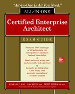
We introduce the set of DoDAF views, organized by viewpoint, for reference in Table 4-1. These DoDAF views are compatible with TOGAF and are a subset of the views/models contained in the FEAF2. Thus, the DoDAF views provide an integrated, basic set. Details of each view and examples related to the airport case study are provided in Part III. The label in the Short Name column is the shorthand name for the view in the DoDAF. The set of letters preceding the “V” is an acronym for one of the DoDAF viewpoints and the number is an arbitrary number assigned to the view within the viewpoint. The view descriptions provided in the table are based on the official definitions from the DoDAF with small changes to enhance clarity. More detailed and specific descriptions of the views are provided in Part III.


Table 4-1 DODAF Views Organized by Viewpoint
Integration of Views
Multiple views may share the same architecture elements or concepts. For example, performers appear in the OV-2: Operational Resource Flow Description, OV-3: Operational Resource Flow Matrix, OV-5b: Operational Activity Model, and OV-6c: Event-Trace Description. As discussed earlier, viewpoints are related to one another by shared architecture elements, so views in different viewpoints may also share architecture elements. For example, activities appear in the OV-5b: Operational Activity Model and in the SV-5b: Operational Activity to Systems Traceability Matrix. Within the same architecture, the activities that appear in the OV-5b should be the same activities that appear in the SV-5b. These activities should map to the same dictionary entries in the AV-2: Integrated Dictionary. In this way, a consistent version of reality is reflected across a single architecture. An architecture whose views are disjoint—that is, whose views should share the same elements but instead reference disjoint or partially disjoint sets of dictionary entries—is useless because the reality it represents is logically inconsistent. Such an architecture can be used only to raise issues and questions as to why it is inconsistent.
Examples in Part III will illustrate and discuss how views should integrate.
Repository and Metamodel
DoDAF has an implicit repository concept in the AV-2: Integrated Dictionary. The AV-2 requires the cataloging of every architecture element and relationship along with its role in the architecture (such as performer, operational activity, system function, information exchange requirement, or needline). The various types of architecture elements form the schema (metamodel) elements of a repository and the relationships between them form schema relationships.
The DoDAF originally provided a DoDAF Metamodel (DM2) to define all the types of DoDAF architecture elements and their intended relationships. The metamodel was useful not only to provide architecture developers with guidance on how the architecture elements in views should fit together and how the views should integrate, but also to provide architecture tool vendors with guidance regarding what syntactic rules their tools should enforce and how to organize the repositories for their tools.
The metamodel for a framework is used to represent a vocabulary of elements that are commonly used and shared across all communities that use the same framework. When architects are using automated tools, the metamodel is implemented inside the tool by the vendor, and the user can only construct diagrams that have symbols and links that can be converted into conformant metamodel object instances inside the tool’s repository. Tools based on the Unified Modeling Language (UML) use a UML mechanism, called a profile, to restrict the scope of class instances. A class is restricted using a stereotype. The DoDAF DM2 metamodel class types and MODAF class types are implemented in a UML tool as a profile called the Unified Profile for DoDAF and MODAF (UPDM). The UPDM is being evolved into an ontology that covers more of the defense related frameworks as discussed later in this chapter.
The following subsections provide an introduction to key elements of the DM2. These elements have been divided up into two main groups—business domain and IT and infrastructure domain—for ease in understanding.
Elements of the Business Domain
The business domain deals with concepts and terms that address operations and business value. This domain focuses on what gets done and how it is managed rather than on IT and automation details. We first present the basic concepts of interest to an Enterprise Level architecture and then the basic concepts for Solution Level architectures. Segment Level architectures may contain a combination of these concepts.
Enterprise Level architectures tie together enterprise vision, strategy, goals, and objectives to the capabilities that support them, the projects that deliver the capabilities, and the organizations that own the projects or use the capabilities. Both objectives and capabilities may have performance measures associated with them. These concepts and their relationships enable the Enterprise Level stakeholders to see how proposed or existing projects align with business objectives. The performance measures provide criteria for evaluating whether the capabilities being delivered by existing projects are meeting expectations. This information enables the enterprise to manage its investments and coordinate its projects.
Figure 4-4 shows basic Enterprise Level concepts and their relationships. The concepts are the items inside the rounded rectangles and the relationships are indicated by the arrows of any style. For example, a Capability is part of a Desired Effect. Dashed arrows represent optional relationships. The concepts and their relationships are discussed next.

Figure 4-4 Enterprise Level business domain concepts and relationships
Most enterprises have vision statements that summarize their missions and views of current or future business objectives. The enterprise has a strategy for achieving its future vision that can be realized by achieving stated goals and measurable objectives. Thus, business objectives are achieved if they meet their performance measures. Another term for these goals and objectives is desired effects. A capability is the ability to perform a desired business function that creates business value and is part of a desired effect. That is, the capability is necessary to achieving the desired effect of the strategy. Capabilities may be organized in a specialization hierarchy (from most general to most specialized), and one capability may be dependent on other capabilities. Capabilities may also have associated performance measures.
Here are some Enterprise Level business domain concept examples from the RMN Airport Case Study. These concepts are relevant to the mid-phase to-be architecture that applies to the first five-year period of the transformation.
• Vision RMN Airport becomes a viable alternative to LAX.
• Desired effect (goal/objective) that realizes the vision Within five years, RMN Airport will have passenger flights to Mexico.
• Performance measure for the objective Number of flights to and from Mexico per time period. Here are the performance goals for this measure:
• At year 5 of the transformation, RMN Airport will have at least one weekly passenger flight to and from Mexico.
• At year 7 of the transformation, RMN Airport will have daily flights to and from destinations in Mexico.
• At year 9 of the transformation, RMN Airport will have daily flights to and from all major Mexican airports and tourist locations (at least five flights daily).
• Capability that is part of the desired effect RMN Airport will be able to handle passenger management processes for international flights (such as customs and immigration).
• Performance measure (for the capability) Number of passengers that can be handled by customs and immigration per time period on average. Here are the performance goals for this measure:
• At year 5 of the transformation, RMN Airport will handle customs and immigration for one incoming international flight (about 200 passengers) per week at an average.
• At year 7 of the transformation, RMN Airport will handle customs and immigration for one incoming international flight (about 200 passengers) per day at an average.
• At year 9 of the transformation, RMN Airport will handle customs and immigration for five incoming international flights (about 1000 passengers) per day at an average.
Capabilities are provided by a capability configuration of personnel, systems, and software that are developed, delivered, and maintained by projects. Organizations within the enterprise use capabilities in their business processes to create business value. Organizations also own—that is, manage and control—projects. The organizations that use capabilities may not own the projects that deliver the corresponding capability configurations. Both organizations and projects may be decomposed into subordinate organizations and subprojects, respectively, although these decompositions are not indicated in Figure 4-4.
In the business domain, Solution Level architectures are focused on the business processes, the roles and organizational structures that perform the processes, and the resources managed and exchanged during the execution of the business processes. These concepts and their relationships enable the enterprise to evaluate current operations, select the best solution alternatives for increasing efficiency or providing new capabilities, and manage transition for business process improvement. Figure 4-5 shows some basic Solution Level concepts and their relationships. This figure uses the same notation as Figure 4-4. The concepts and their relationships are discussed next along with some additional concepts that are not shown in the figure.

Figure 4-5 Solution Level business domain concepts and relationships
Performers are those who perform the activities of a business process. A performer may be a role or an organization—or, in the case of activities that are fully automated, such as a sensor or agent software, a performer may be IT. An activity may be an entire business process or a task within a business process. Activities may be decomposed down to the needed level of detail. An activity or business process may have associated performance measures that provide the criteria for judging the effectiveness of the activity. Activities support capabilities. Activities may be constrained by business rules based on policy, operational standards and guidelines, or corporate culture. Performers perform activities at locations. Each activity may be performed at one or more locations. Locations may be abstract or logical, such as “Regional Office,” if all regional offices are sufficiently alike for the purposes of the architecture, or concrete, such as “St. Louis, MO, Regional Office.” Locations are increasingly mobile. Examples of mobile locations are the combat information center aboard an aircraft carrier and the more abstract “personal office” carried by a traveling salesman in his briefcase or car.
To perform their operations, performers may need to exchange resources with other performers. As part of their operations, performers may produce resources that they provide to other performers. These resources may be data, information, personnel types, or materiel (that is, non-personnel physical resources). If the resources are data or information that are sufficiently complex in terms of structure or relationships, they may be modeled in a conceptual or logical data model.
Here are some Solution Level business domain concept examples from the RMN Airport Case Study:
• Performer Check-in agent
• Performer Passenger
• Organization Airline
• Activity Check-in passenger
• Resource Identity documents
Check-in agent (performer) employed by airline (organization) performs check-in passenger (activity). Check-in agent needs identity document (resource) from passenger (performer) to perform check-in passenger.
Additional Solution Level concepts relate to the dynamic behavior of the architecture and are not covered in Figure 4-5. These concepts are the state behavior and the scenario behavior.
State behavior is usually a characteristic of data entities or information elements. The state of a data entity or information element changes in response to events caused by the execution of business processes. Typically, a data entity or information elements will transition through a sequence of states, from some initial state to some terminal state, during the course of normal business operations. For example, in the RMN Airport Case Study, the passenger has state or status that changes as the passenger is processed through the airport and onto the airplane. This state or status is included in the passenger record and is queried and updated by various passenger management processes. Some examples of status for a passenger are checked-in, screened, and boarded. Not all information or data entities will have interesting state behavior, so this type of behavior is modeled in an architecture only when understanding state behavior is important to understanding the enterprise’s business.
An operational scenario shows business behavior in terms of interactions among the performers in response to the specific sequence of events contained in the scenario. The scenario highlights the resource exchanges among performers in response to a specific sequence of events generated by the execution of one or more business processes. The scenarios chosen for an architecture usually relate to key operational concepts or performance or security-critical sequences.
As usual, in the business domain, Segment Level architectures can have elements that can appear in both Enterprise Level architectures and Solution Level architectures.
Elements of the IT and Infrastructure Domain
The IT and infrastructure domain deals with concepts and terms that address systems, services, standards, and communications and how they support the business domain. This domain focuses on the details of systems or services and infrastructure functions, interfaces, performance, and resource exchanges, and how all these items support business process needs. Here, systems and services are usually provided by automation, but, as automation continues to become more sophisticated and the infrastructure becomes more capable and pervasive, systems may be viewed in the traditional systems engineering way, by inclusion in organizational structures and personnel. The inclusion of the relationships between system or services and the business domain is critical. Without this connection, a basic purpose of EA—that is to ensure that IT supports business needs and goals—cannot be achieved. Because of the need to show this connection, it is hazardous to develop business domain and IT domain architectures independently. There needs to be a strong coordination between the developments of these two domain architectures to achieve an integrated, useful EA.
The IT and infrastructure details are usually of more concern for Solution Level architectures, although Enterprise Level architectures are concerned with the overall IT and infrastructure interoperability and integration issues, including technical standards and delivery and retirement dates for capability configurations. The IT and infrastructure domain can be viewed from either a system-oriented or a service-oriented approach. We first present the basic concepts for a system-oriented viewpoint and then the basic concepts for a service-oriented viewpoint. Last, we discuss some basic concepts for communications infrastructure.
System Viewpoint Elements
A system viewpoint looks at the IT and infrastructure domain as a set of systems with interfaces, where each system performs a set of system functions, exchanges resources (usually data), and has performance measures. Figure 4-6 shows some basic IT and infrastructure domain system viewpoint concepts and their relationships that will be discussed next along with some additional concepts that are not shown in the figure.

Figure 4-6 IT and infrastructure domain system viewpoint concepts and relationships
A system can be decomposed into component systems (in cases of SoS or FoS), subsystems, or system components. A system (or decomposed system) has interfaces to other systems. Each interface carries data between (out of and into) systems. Both systems and interfaces may have standards that apply to them. That is, systems and their interfaces may implement standards. Each system is located at one or more locations. A location may be logical or physical, and it may be mobile.
A system performs a set of functions, each of which can be decomposed into subfunctions. Each function has one or more logical data flows that carry data from or to that function. Each system can be mapped to the business activities it supports either directly or indirectly through the functions the system performs. Both systems and functions may have Performance Measures associated with them.
Data models can be used to describe the data managed by a system. For example, a data model can be used to describe the logical or physical schema of a shared database managed by a system. A data model can also be used to describe the data that flows between functions or between systems on interfaces, if this data is sufficiently complex.
Here are some solution level IT and infrastructure concept examples from the RMN Airport Case Study:
• System Airline Reservation and Ticketing System (ARTS) client and server
• Function Verify passenger identity
• Location Check-in counter
• System Passenger Intelligence Services (PaxIS)
• Location RMN operations center
• Interface ARTS to PaxIS
• Activity Check-in passenger
The ARTS client (system), located at the check-in counter (location), supports check-in passenger (activity) by performing verify passenger identity (function) among other functions. The ARTS server has an interface to PaxIS.
Additional concepts associated with the systems viewpoint include system and standard availability, updates, and retirement dates and behavior concepts. Like the business domain, there may be system rules that constrain system structure, interfaces, and function. Systems may have internal states. In fact, this is usual for control and similar systems. Unlike business objects, system behavior is frequently continuous. Systems start in an initial state, transition state based on external system inputs, and cycle back to an initial state, ready to begin performing the set of functions again.
A common example of a control system that has state is the control system for a vending machine. In this case, in its initial state, the machine is ready to accept money. After sufficient money is inserted, the machine transitions to a state where input from the item selection buttons can be accepted. After a legitimate product code (whose cost is equal to or less than the amount previously inserted) is selected and the selected item is dispensed, the machine transitions to a state where change may be calculated and, if necessary, dispensed. Then the machine returns to its initial state.
System scenarios are also important for modeling system behavior. A system scenario shows the interactions of systems (or system components) in terms of data exchanges in response to a specific sequence of system events or external inputs, such as sensor inputs. The scenarios selected for an architecture usually relate to key performance or security critical sequences.
Service Viewpoint Elements
A service viewpoint looks at the IT and infrastructure domain as a set of usually web accessible services that can be quickly configured to create new or updated applications. In the service viewpoint, much of what is considered a system, including the platform and operating system, becomes infrastructure for the services. Each service is defined with a standard interface. Ideally, multiple implementations of this service may be available, either from multiple vendors or for multiple platforms. Each implementation has an SLA that spells out such items as the performance characteristics promised by the service provider. Figure 4-7 shows some basic IT and infrastructure domain service viewpoint concepts and their relationships, which will be discussed next along with some additional concepts that are not shown in the figure. Sometimes services are not just IT services, but business services, in the cases where the enterprise relies on outside parties to perform these services. For example, a government agency or corporation may decide to outsource payroll services. The following discussion relates primarily to IT services.

Figure 4-7 IT and infrastructure domain service viewpoint concepts and relationships
Each abstract service may specialize to more specific abstract services. For example, in the case of search and rescue services (which are business services), there may be specialized water search and rescue and mountain search and rescue services. Each abstract service may also depend on—that is, call upon—other abstract services. For example, a payment-handling service may call on a credit card service and a check-handling service. Each abstract service has a standard interface as part of its service definition. The standard interface describes the data consumed by the service (that is, required as input) and the data produced by the service (that is, produced as output). A data model may be used either to describe the data produced and consumed by services, if this data is complex, or to describe the data managed by a service, if the service is managing a database of shared data.
Each abstract service has one or more service implementations. Implementations may differ in terms of their development and maintenance organizations (that is, different vendors), in terms of the platforms they run on, or in terms of their performance characteristics. Each implementation typically has an SLA that includes the performance characteristics that are guaranteed for the service implementation. Like systems, service implementations run at one or more locations. For services, the concept of location also includes the concept of platform, or system infrastructure that is supporting the service. The location of the platform may be abstract, physical, or mobile. Unlike most systems, the number and location of implementations for a given service may change dynamically. That is, if a service implementation at a specific location becomes overloaded with service requests, then additional implementations of that service may be brought up at that location or other locations to maintain response performance. If a service implementation at a specific location becomes inaccessible because of communications problems, additional implementations of that service may be started up in locations that remain accessible.
Like systems, services need to be mapped to the business activities they support. Each service will support one or more business activities.
Additional concepts associated with the service viewpoint include service implementation availability, update, and retirement dates and behavior concepts. A service or service implementation may have associated rules. For example, a service implementation may have criteria for deciding when that implementation is becoming overloaded with requests. The related abstract service may have rules for deciding where additional implementations should be instantiated if an implementation becomes overloaded. Like systems, services may have internal state. Service scenarios are also important for modeling the behavior of sets of services. A service scenario shows the interactions of services in terms of data exchanges (that is, service requests and responses) in response to a specific sequence of events or external inputs caused by the execution of an application that uses the set of services. The service scenarios included in an architecture may be selected to demonstrate the effectiveness of the set of services in supporting critical applications, or they may be selected based on key performance or critical security issues.
Communications Infrastructure Elements
The communications infrastructure is the network and communication systems, such as satellite relays, radio repeaters, routers, and gateways, whose purpose is to move data rather than to process it for operational purposes. The communications infrastructure implements the system interfaces shown in Figure 4-6 and the communication aspects of service standard interfaces shown in Figure 4-7. The communication infrastructure concepts and relationships are shown in Figure 4-8 from a systems viewpoint perspective. Communications infrastructure information is of interest to stakeholders who focus on reliability and availability of data and security issues.

Figure 4-8 Communications infrastructure concepts and relationships
A system sends data to external systems through one or more system ports. Each system port implements a standard protocol that is used to send the data via a sequence of communications links and communications systems that use the protocol to reach the system port on the receiving system. Frequently, there are multiple possible paths in a communications network that realize system interfaces, especially when the Internet is used.
Ontology
Once other defense organizations started to develop their own frameworks based on DoDAF, the original metamodel was not sufficient for this larger community. Defense organizations in allied countries sometimes wanted to share architecture information but had difficulties moving the data between tools because the metamodel vocabulary for their frameworks was no longer consistent. Thus, the DM2 evolved into an ontology: the Unified Profile for DoDAF and MODAF (UPDM). This evolution was fueled both by government interest and by tool vendors under the auspices of the OMG, a commercial and technology industry–based standards-making body. UPDM was represented in a UML profile that offered a way for UML tools to exchange architecture data via XML.
Since UPDM is based on DM2, the impact of UPDM on architecture developers is to make it easier to find tools that will enforce the syntactic rules for views in a consistent way and that will be able to exchange architecture data easily. The concepts of DM2 discussed previously still hold true for architecture developers.
UPDM has evolved through several iterations and is currently being extended to additional defense frameworks under the proposed OMG standard Unified Architecture Framework (UAF) and to SysML under the proposed OMG standard Unified Architecture Framework Profile (UAFP). This work is aimed at allowing a wider range of DoDAF-related defense architecture frameworks to exchange architecture data between both UML and SysML tools using XML.
Note that, despite their names, the UAF and UAFP are not frameworks, but ontologies. Confusingly, UAFP introduces additional “views” not included in the DoDAF to reflect relationships in its ontology. Understanding of the details of UAF and UAFP is not necessary for architects using tools based on these ontologies. The point of these profiles is that these tools will enforce the ontology and keep the architecture integrated.
Process: The Six-Step Process
The Six-Step Process is a high-level or metaprocess for architecting. It does not provide a specific, detailed process for developing architecture artifacts, products, or data, but rather sets the context for this more detailed architecture development process. This approach lets the development organization select and use its own detailed architecture development process. Other comprehensive approaches, such as the Architecture Development Methodology (ADM) from TOGAF and the Collaborative Planning Methodology from FEAF2, discussed in Part IV, cover similar topics.
The Six-Step Process is the metaprocess provided by the DoDAF and the Practical Guide to Federal Enterprise Architecture. This process is illustrated in Figure 4-9. Although the steps are followed in numerical order, the process tends to be highly iterative. For simplicity, only one iteration arrow (from step 5 to step 3) is included in the figure. The architecture team gains more insight into the architecture domain with each step of the process, and each new insight may cause the team to return to an earlier step to refine previously developed material or add new material. Each step of the Six-Step Process will be discussed briefly here and in detail in Chapters 5 and 6. Note that step 1, determine the intended use of the architecture, is a critical, and too often skipped, step that drives all the other steps.

Figure 4-9 The Six-Step Process
Step 1: Determine the Intended Use of the Architecture
Step 1 focuses on identifying why the architecture is being built: what problem or problems the architecture should address, including who the architecture stakeholders (the users of the architecture) are and what decisions they are going to use the architecture to support. Each stakeholder will have a set of specific questions that the architecture will need to provide the answers to or analyses that the architecture will need to support. The architecture stakeholders considered here go above and beyond the usual set of stakeholders considered in system development, because a wide range of decision-makers in addition to system or even business process sponsors, owners, or users may use the architecture information in decision-making processes. For example, for all federal departments and agencies, the Office of Management and Budget (OMB) uses architecture information to decide which proposed projects get funding or which continuing projects get additional funding. In DoD, the Battle Integration Laboratories use architecture information to support integration testing across multiple, independently developed systems.
In the case study, the purpose of the RMN Airport Enterprise Level architecture is to support the transformation of RMN Airport from a civil aviation airport to a viable alternative to LAX. Stakeholders in the Enterprise Level architecture (users of this architecture) include the appropriate port authority, the RMN Airport management, and, potentially, the local governments of the communities surrounding the airport and the local citizens. The port authority and RMN Airport management need the architecture to identify and document the additional capabilities or business services that RMN Airport needs and to support the transition planning and projects for implementing these additional capabilities. The local governments and citizens will use the Enterprise Level architecture to analyze and understand how and when the airport changes will impact their communities in terms of noise, additional traffic, and expanded airport space and facilities.
Step 1 is critical since architecture is a decision-making tool, so it is vital to understand the decisions the architecture will be used to support. Many organizations jump immediately to step 4 and start collecting data and building models without careful consideration of what data is actually needed and how the data will be used. As a result, these organizations, after having expended large amounts of money, have found themselves with extensive models and mountains of data but with no real idea of how any of this data will support their key decision-making processes.
The material developed in step 1 will drive the selection of data and artifacts for the architecture, the level of detail needed, and completion criteria for the architecture.
Step 2: Determine the Scope of the Architecture
Step 2 focuses on identifying the boundaries of the architecture—what is internal to the architecture and what is outside the scope of the architecture. Scope includes the level of the architecture (enterprise, segment, or solution), mission or organizational boundaries, technology and time frame constraints, or other scoping issues.
In the case study, the example Segment Level architecture is limited to business processes and organizations at RMN Airport that are involved with passenger management, including passenger-related business services. For example, some of these passenger-related business processes could be supplying information to RMN Airport financial systems so that the airport can bill airlines for services based on the number of passengers that enter or leave the airport on that airline’s flights. However, the financial business processes and systems would be considered outside the scope of the passenger management segment architecture even though the passenger management segment would need interfaces to these financial business processes and systems.
Step 3: Determine the Data Needed to Support Architecture Development
Step 3 focuses on identifying the types of data needed to answer the problems and issues identified in step 1, within the scope limitations set out in step 2. Each of the architecture stakeholder questions from step 1 should lead to a set of data types that will be involved in answering the question. For example, if one of the questions is “What changes will the new systems bring to our business processes?” then the architecture will need to include the current (as-is) and new (to-be) business process data for the business processes within the mission or organizational and time frame scope provided by step 2.
Step 4: Collect, Organize, Correlate, and Store Architecture Data
In step 4, the set of architecture views is selected and developed. The views are selected to cover the data identified in step 3. Mathematical modeling techniques may be used to ensure that the data collected is consistent, complete, and correctly correlated. The development organization’s specific architecture development process guides the techniques to use and the order in which the views are built. The specific architecture development process also guides the tools and data storage approach used.
Step 5: Conduct Analyses in Support of Architecture Objectives
In step 5, the data resulting from the various view development efforts in step 4 are analyzed. There are two types of analyses that may be employed in this step. One type is the analysis needed to address issues involved in the development of the architecture, such as which of several operational process or system support options is most effective, based on the overall performance measures associated with the architecture. Another type is analysis that directly addresses the decision-making processes that the architecture is designed to support. This type of analysis often involves both architectural and, potentially, other types of data such as financial data. Examples of this second type of analysis include business case analysis, return on investment analysis, and various types of performance and sensitivity analyses based on executable architecture modeling.
In all cases, the analysis processes may uncover the need for additional types of data that were not originally identified in step 3. Thus, Figure 4-9 shows an iteration arrow going from step 5 to step 3. The need for additional types of data will also cause iteration of step 4 so that this additional data can be collected, correlated, and integrated with the current architecture data set, and stored, so it can be used for further analysis, sharing, and future use and reuse.
Step 6: Document Results in Accordance with Decision-Maker Needs
In step 6, the data developed in step 4 and refined through step 5 is used to develop artifacts and products, also called fit-for-purpose views, which are used to communicate the results of the architecture process to the stakeholders and provide direct support to their decision-making processes. For some stakeholders and questions, the results can be documented using the same models the architecture development team developed in step 4. For other stakeholders, the results must be provided in other formats that are more easily understood by non-architects, such as bar or pie charts, dashboards, or combinations of simple graphics and text. The fit-for-purpose views or non-mathematical models are based on the consistent, correlated data stored during step 4. For example, to support the local government and citizen stakeholders, the data developed during steps 4 and 5 for the RMN Airport Enterprise Level architecture might be used to generate a fit-for-purpose view that was a bar chart showing the planned increase in air traffic for the airport by year. This relationship of mathematically based models or architect’s views to the consistent, integrated, architectural knowledge base, to the stakeholder-oriented fit-for-purpose views, is illustrated in Figure 4-10.

Figure 4-10 Relationship of data and views in architecture (figure based on DoDAF graphic)
For communicating the architecture contents to other architecture teams that are working on related architectures, a standard set of artifacts may be used. For example, the DoDAF provides a standard set of viewpoints and views for communicating architecture results within the DoD architecting community. From the implementation perspective, the knowledge base, built on a common data model, can be shared, and tools can be used to generate the standard views. With standard views, the architects do not have to learn all possible modeling techniques but only those involved with the standard views.
Summary
This chapter introduced the basics of the DoDAF. It covered the three levels of enterprise architecture (Enterprise Level, Segment Level, and Solution Level), their relationships, and the contexts in which they are used. It introduced the DoDAF viewpoints and views and discussed the concept of view integration.
This chapter introduced the DM2 and some of its key concepts and their relationships. These concepts and relationships underlie all the architecture views and form the basis for many tool repositories. It discussed the evolving “deep structure” ontologies derived from DM2 that make it possible to have tools that can exchange architecture data easily.
The chapter also introduced a metaprocess for developing a DoDAF architecture: the Six-Step Process. The Six-Step Process sets the context in which an organization’s specific enterprise architecture development process can be applied. The focus on the Six-Step Process is on understanding the purpose and uses of the enterprise architecture so that the development effort can be concentrated on useful data and views and the architecture can be formulated in standard ways for sharing with the community of interest. More detail on the Six-Step Process will be presented in other chapters.
Questions
1. What is the relationship between an organization’s specific architecture development process and the Six-Step Process?
2. Why should the Six-Step Process be considered as an iterative process?
3. What architecture concepts are common between the Solution Level business domain and the IT and infrastructure domain system? What do these common concepts imply about the relationships between the business domain and the IT and infrastructure domain?
4. What architecture concepts are common between the Enterprise Level business domain and the Solution Level business domain?
5. What are the different architecture concepts that can have performance measures associated with them? Why are these performance measures important?
6. What are the different concepts that can be related to a data model?
References
Department of Defense. 2009. Department of Defense Architecture Framework Version 2.0. http://dodcio.defense.gov/Library/DoD-Architecture-Framework.
DeVries, David. 2013. “DoD Joint Information Enterprise,” DoD Deputy Chief Information Officer for Information Enterprise. http://c4i.gmu.edu/eventsInfo/reviews/2013/pdfs/AFCEA2013-DeVries.pdf.
Director, Architecture & Interoperability Office of the DoD Chief Information Officer. 2012. “DOD Enterprise Architecture: Core Data Center Reference Architecture, Version 1.0.” http://dodcio.defense.gov/Portals/0/Documents/DIEA/CDC%20RA%20v1_0_Final_Releaseable%20Version.pdf.
Object Management Group. 2013. Unified Profile for DoDAF and MODAF Specification Version 2.1. www.omg.org/spec/UPDM/2.1/.
Object Management Group. 2016. Unified Architecture Framework Profile, Version 1.0 – FTF Beta 1. OMG Document Number dtc/16-08-01. www.omg.org/spec/UAF/1.0/Beta1/About-UAF/.
Object Management Group. 2016. Unified Architecture Framework (UAF): The Domain Metamodel, Version 1.0, Appendix A.
Office of the Assistant Secretary of Defense, Networks and Information Integration (OASD/NII), Department of Defense. 2010. Reference Architecture Description. http://dodcio.defense.gov/Portals/0/Documents/DIEA/Ref_Archi_Description_Final_v1_18Jun10.pdf.
Takai, Teresa. 2013. “DOD Enterprise Architecture: Unified Capabilities Reference Architecture, Version 1.0.” http://dodcio.defense.gov/Portals/0/Documents/DIEA/Approved%20DoD%20UC%20Reference%20Architecture.pdf.
U.S. Army. 2014a. Identity and Access Management (IdAM) Enterprise Architecture Reference Architecture (RA), Version 4.0.
U.S. Army. 2014b. Network Security Enterprise Reference Architecture, Version 2.0.