CHAPTER 6
![]()
Light-Emitting Diodes
In this chapter we will explore light-emitting diodes (LEDs) of different emitted wavelengths (e.g., red, green, and blue), and how their “turn-on” voltages (VF) are related. We will also discuss common problems that can cause an LED to fail, such as over current or “excessive” reverse voltage.
The LED’s Light Output
Light-emitting diodes are measured for luminous intensity (light output) in milli-candelas (mcd) at a particular LED current. There are various descriptions of LEDs such as “high efficiency,” “high intensity,” or “high performance.” However, the most important specification to look for is the light output for a given LED current, which is usually done at 10 mA or 20 mA.
With the exception of using older LEDs that give out about < 10 milli-candelas at 10 mA current, which are suitable for indicator lamps such as power-on lights, you will find that most LEDs are much brighter.
For example, typical LEDs will provide over 1000 mcd at 20 mA. In keychain LED flashlights or multiple LED flashlights, the rating is in the order of > 10,000 mcd at 20 mA. The extra brightness works well in products such as light cubes, photographers’ studio or portable lighting, emergency lights, home light bulbs and light fixtures, or automobile headlights.
Here are some basic rules of thumb on LEDs:
• For indicator lamps, generally with today’s LEDs of any color—red, green, yellow, blue, or white—the LED current can be in the 1 mA to 5 mA range. With very high-brightness LEDs such as a 20,000 mcd unit, the drive current can be as low as 0.10 mA or 0.25 mA.
• If you are using LEDs to generate intense lighting such as making a flashlight or a light cube, you should not exceed 20 mA per LED. Otherwise, the LED may take in excessive current, which causes it to burn out.
• For those situations where intense LED light is generated, do not look directly into the LED light source. You can damage your eyesight.
• The light output is generally proportional to drive current. For example, if you are using an LED that is providing 20,000 mcd at 20 mA. Suppose you want to turn it down so that it can be used as an indicator lamp. If the LED drive current is reduced by 200 times from 20 mA to 0.10 mA, the LED will output 100 mcd, which is still pretty bright for an indicator lamp.
NOTE: 20,000 mcd divided by 200 = 100 mcd.
Standard LEDs come in 3mm, 5mm, and 10mm sizes. In this chapter, we will be looking at the common 5mm types that have 100 mil (0.1 inch) lead spacing.
Now, let’s take a look at some LEDs.
Figure 6-1 shows a red, green, and yellow 5mm size LED from left to right. Notice that each of the LEDs comes with a longer lead, which is identified as the anode. Each of these LEDs will turn on at less than 2 volts DC, typically about 1.7 volts. Also, they have a “frosted” lens that allows for a wider viewing angle and is easier to look at because the light is more diffused.
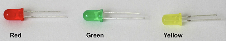
FIGURE 6.1 Red, green, and yellow LEDs give out “diffused” light due to their encapsulations with their associated colors.
In Figure 6-2, the blue and white LEDs turn on at a higher voltage, around 2.5 volts to 3.0 volts DC. The blue and red LEDs have a frosted lens that allows for a wider viewing angle. The middle clear lens, white LED is made for maximum brightness but over a narrower viewing angle. Clear lens LEDs are used for flashlights or for efficient projection/illumination of a smaller area.

FIGURE 6.2 A blue, white, and again a red LED (shown from left to right) that are 5mm in size.
Again, the spacing between the two leads in 5mm LEDs is 0.1 inch.
To identify the LED’s anode and cathode leads see Figure 6-3.
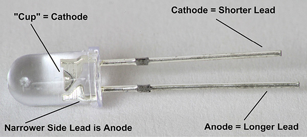
FIGURE 6.3 Identifying the anode and cathode leads by length or by locating the “cup” that is connected to the cathode lead. From the side of the LED, the narrower lead as shown is the anode.
We now turn to the LED’s schematic symbol. See Figure 6-4.

FIGURE 6.4 An illustration identifying the anode and cathode via the lead lengths (e.g., longer lead is the anode) and its schematic symbol with two outward arrows signifying light emission.
It should be noted that the schematic symbol is often drawn vertically. See Figure 6-5.
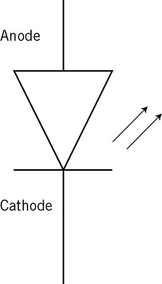
FIGURE 6.5 Often the LED symbol is drawn vertically with the cathode grounded and the anode connected via a resistor to a positive power supply.
Before we look at lighting up LEDs, there is one “trick” to always identify a white light LED. See Figures 6-6 and 6-7.
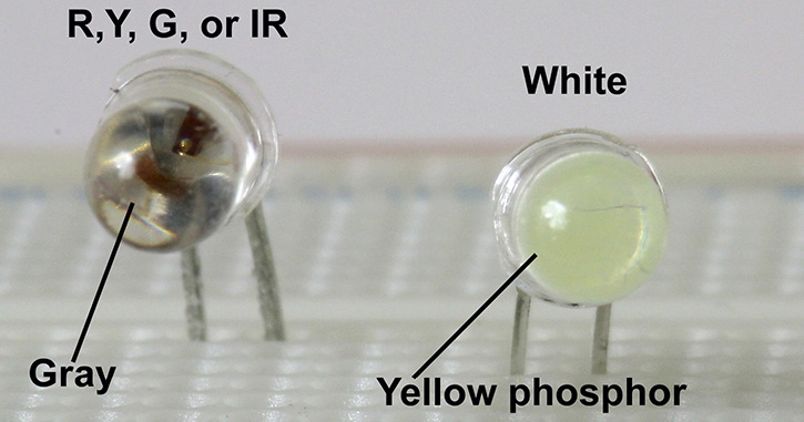
FIGURE 6.6 A red (R), yellow (Y), green (G), or infrared (IR) LED on the left, and a white LED on the right.
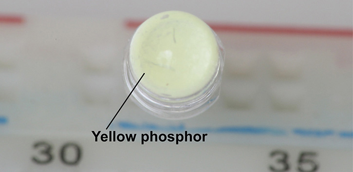
FIGURE 6.7 Viewing straight from the top, you will see yellow throughout, which signifies that this is a white LED.
In Figure 6-6 you can always identify a white light LED by its yellow phosphor when looking directly into it without power applied to it. If you see “gray,” it is an LED other than white.
Figure 6-7 shows a closer look at the white LED’s yellow phosphor.
NOTE: A burnt-out white LED may be missing the yellow phosphor.
The yellow phosphor is excited by a blue LED below it, which, when combined, forms a white light. Note that on the color wheel, blue and yellow are at opposite ends. In fact, if your photo has a yellow color cast, you add blue to remove the yellow cast. Conversely, if the photo has a blue cast to it, you add yellow to return the picture to normal colors.
LED “Minimum Turn On” Voltages
In this next section we will measure the turn-on voltages for LEDs. The turn-on voltages of particular LEDs are relatively constant, almost regardless of LED current. This means that a slight voltage increase (e.g., +100 mV DC more than the previous voltage) across the anode to cathode leads can result in an increase in LED current by tenfold or more. This is why generally LEDs are driven by a resistor or some type of current limiting device such as a transistor.
When the LED voltage and current characteristics are well known, then sometimes a voltage source can be applied to the anode and cathode terminals. For example, we see this in some three AAA cell multiple LED flashlights. See Figure 6-8. In this specific case, there is somewhere between 3.6 volts to about 4.0 volts directly across the anode and cathode of each of the white LEDs. The minimum turn-on voltage of white LEDs is between 2.5 volts and 3.0 volts. Although there are three 1.5-volt AAA cells in series to provide nominally 4.5 volts, by the time all the LEDs are lit, there is enough current draw to lower the three AAA batteries’ 4.5 volts to about 4.0 volts or lower (measured 3.93 volts with three alkaline AAA cells when the LEDs are turned on), which is just safe enough to prevent the LEDs from burning out. In this example, the three series connected AAA cells have sufficient internal current limiting resistance. This allows the LEDs to be powered on safely.
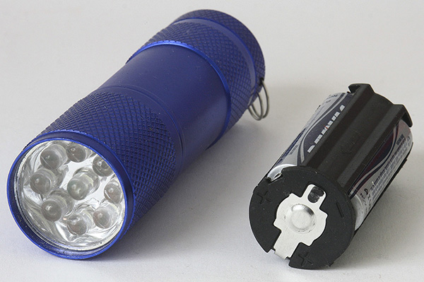
FIGURE 6.8 A three AAA cell 9 LED flashlight, where the LEDs are matched in terms of turn-on voltage.
NOTE: If you use higher capacity batteries that have lower internal resistance than the AAA batteries such as C or D cells, the LEDs’ life may be shortened significantly due to excessive current. The reason is that the LEDs will essentially receive the full 4.5 volts from the three series connected C or D alkaline cells.
In Figure 6-8, the three AAA cells are connected in series and provide sufficient internal series resistance for LED current limiting. The nine matched LEDs are connected in parallel (e.g., all nine anode leads and all nine cathode leads are connected) that provide equal brightness among each of the LEDs.
If you randomly take nine white LEDs and connect them in parallel, the brightness will vary between some of these nine LEDs due to different turn-on voltages.
For long LED life, you will need to drive them with batteries that have some internal resistance. Using three AAA batteries will be fine for driving the LEDs within their current limits. But to reiterate, if you drive the LEDs with three C or three D cells, you can burn out the LEDs. The reason is that the C and D cells have lower internal resistance (than the AAA cells) and can deliver much more current into the LEDs.
Now let’s take a look at LEDs whose turn-on voltages are typically less than 2 volts DC from anode to cathode. See Figure 6-9.

FIGURE 6.9 LED turn-on voltages (VF) of 1.786 v = Red, 1.872 v = Green, and 1.842 v = Yellow. The drive voltage is 9 volts with an 8060Ω 1 percent series resistor for each LED.
See Table 6-1 for color and wavelength related to Figure 6-9.
TABLE 6.1 LED Turn-On Voltages and Their Wavelengths
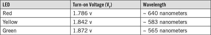
Notice that the turn-on voltages increase as the wavelengths get shorter. For example, the longer wavelength red LED has 1.786 volts turn-on voltage, whereas the shorter wavelength green LED has a turn-on voltage of 1.872 volts.
See Figure 6-10 for a schematic diagram of the LEDs being lit in Figure 6-9. In this schematic the LEDs have one arrow emanating from them to denote light emission. Generally, whether there is one or two arrows emanating from the diode symbol, the meaning is the same—the diode is an LED.

FIGURE 6.10 Schematic diagram of the red, green and yellow LEDs with their respective forward voltages (VF) at 1.786 v, 1.872 v, and 1.842 v.
The forward LED current (IF) is the battery voltage minus VF divided by the drive resistor, such as R1, R2, or R3.
For example, the current flowing through the red LED is
IF = (9 volts – 1.786 volts) / R1 = (9 volts – 1.786 volts) / 8060Ω
IF = 7.214 volts / 8060Ω
IF = 0.895 milliamp
Notice in Figure 6-10, a “ground” or common point terminal has been added that is connected to the negative terminal of the 9-volt battery. Often, the DVM’s negative or black test lead is connected to the ground or common point. Then the DVM’s red test lead is “free” to probe or measure for voltages at different parts of a circuit.
Now let’s take a look at turn-on voltages for blue, white, and red LEDs.
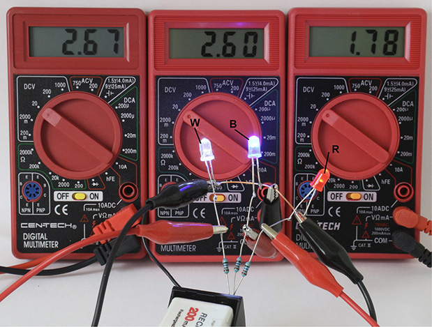
FIGURE 6.11 White (W), blue (B), and red (R) LEDs lit via a 9-volt battery and 8060Ω resistors.
Both white and blue LEDs are very bright, and the blue LED is actually overexposing the camera’s sensor. See Figure 6-12 for another look at these three LEDs lit.

FIGURE 6.12 The white (W), blue (B), and red (R) LEDs lit.
Now let’s take a look at Table 6-2, a summary of the turn on-voltages for white, blue, and red LEDs.
TABLE 6.2 Turn-On Voltages for White, Blue, and Red LEDs
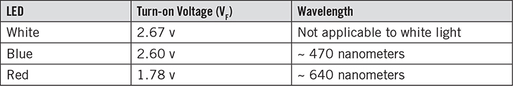
Note that since a white LED really uses a blue LED inside with a yellow phosphor, both white and blue LEDs have essentially identical turn-on voltages, 2.67 volts and 2.60 volts.
A schematic diagram is shown in Figure 6-13.

FIGURE 6.13 A schematic diagram showing the turn-on voltages (VF) measured for white, blue, and red LEDs.
Again, we can determine the forward LED current (IF) by the following:
IF = (supply voltage – VF) / drive resistance
For the blue LED, we have:
IF = (9 volts – 2.60 volts) / R2
IF = (9 volts – 2.60 volts) / 8060Ω = 6.40 volts / 8060Ω
IF = 0.794 milliamp
Other Types of Green LEDs
In Table 6-1, we found that the green and yellow LEDs had very close turn-on voltages at 1.872 and 1.842 volts. And if you look carefully at these types of green and yellow LEDs, we notice that the green LED gives closer to a green-yellow color instead of a darker or deeper green hue without much yellow. (See Figure 6-9 for an example). It turns out that there are green LEDs that are closer to green-blue in tint, which is a “truer” rendition of what we think of as green color.
Also, there are LEDs that give out more light such as the green 1-watt LED in Figure 6-14.
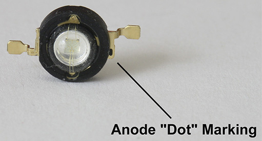
FIGURE 6.14 A 1-watt LED with its anode marking as shown with the dot on one lead. At 1 watt, the maximum current for this LED is about 300 mA. The LED has to be heat-sinked properly by soldering the two leads to large areas of copper that dissipates the heat away.
Let’s take a look at the turn-on voltages between a standard green-yellow LED and a green-blue LED. See Figure 6-15.
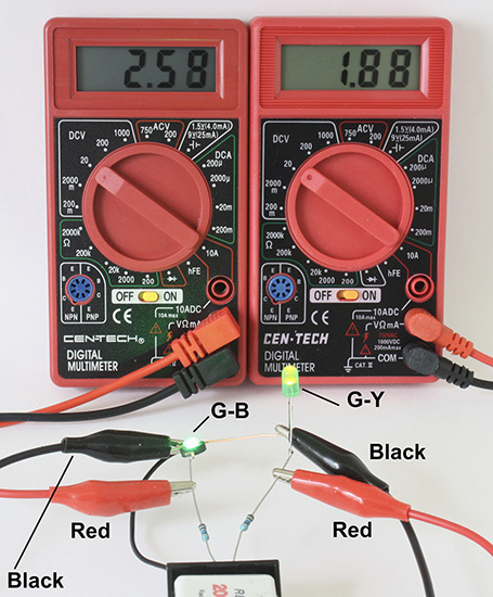
FIGURE 6.15 The 2.58-volt turn-on voltage for the (phosphor) green-blue (G-B) LED is closer to the turn-on voltage of LEDs that are white (2.67 v) or blue (2.60 v). Note that a standard green LED, which gives green-yellow (G-Y) light has a turn on voltage of 1.88 v.
We can see a difference in colors of the two “green” LEDs in Figure 6-16.

FIGURE 6.16 A shorter wavelength green-blue (528 nm) LED on the left shows a deeper green compared to the longer wavelength green-yellow (565 nm) LED on the right. Note: nm = nanometers.
Although the example in Figure 6-16 shows a 1-watt LED, the green-blue LED is available in the same (5 mm) size as the green-yellow LED.
Problems with Paralleling Two LEDs with Different Turn-On Voltages
In Figures 6-9 to 6-13, 6-15, and 6-16 the LEDs are driven via a series resistor so that the LED current can be controlled more precisely. For example, see Figure 6-17.
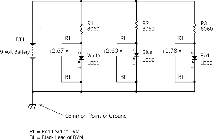
FIGURE 6.17 These LEDs include series current-limiting resistors R1, R2, and R3.
However, what happens if we only drive 2 paralleled LEDs with just one current-limiting resistor? See Figure 6-18.
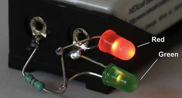
FIGURE 6.18 A red LED and a green LED connected in parallel are driven via one series current-limiting resistor. Note that the red LED is much brighter than the green LED.
For a close-up of the two LEDs, see Figure 6-19.
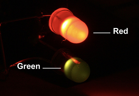
FIGURE 6.19 A close-up view of the two LEDs in parallel that shows the green LED being much dimmer than the red one.
The circuit is shown schematically in Figure 6-20.
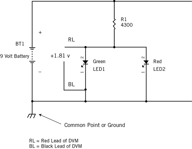
FIGURE 6.20 Two LEDs are wired in parallel with a single series resistor R1.
The measured voltage across the two LEDs is 1.81 volts. However, from Figure 6-9, the different turn-on voltages with 8060Ω driving resistors resulted in 1.786 volts for red and 1.872 volts for green. Hence, there is about an 86 mV difference with the red LED that turns on with a lower voltage. As shown in Figure 6-20, the measured voltage at the anode is 1.81 volts with a 4300Ω resistor. Note that the red LED’s 1.81-volt VF is still lower than the 1.872-volt turn-on voltage of the green LED in Figure 6-9. Hence, the red LED will divert or hog most of the current and it will light up brighter than the green LED (see Figure 6-19).
In general, if you are going to parallel LEDs together, first they should be of the same color emission. Second, they should be matched, which, for example, can be done by purchasing the LEDs in “tape” form. See Figure 6-21.
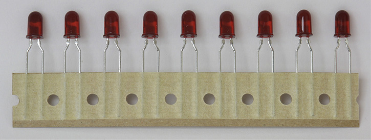
FIGURE 6.21 LEDs bought in tape form are generally better matched in terms of turn-on voltages than those bought in a bag or off the shelf.
Protecting LEDs from Damage Due to Reverse Voltage Across the Anode and Cathode
If you are going to connect LEDs to an AC (alternating current) voltage source such as an AC adapter that gives AC voltage (e.g., 6VAC, 9VAC, 12VAC, etc.) you will need to protect the LEDs from damaging reverse voltage. Recall that AC voltages provide positive voltages at one time followed by a negative voltage at another time.
For example, a 60 Hz AC voltage source has a repetition rate of (1/60) second or 16.666 millisecond. In the first half of that period, the voltage is positive for 8.333 milliseconds (e.g., half cycle). And in the next 8.333 milliseconds (e.g., the remaining half cycle) the voltage is negative.
LEDs only have a peak reverse “breakdown” voltage of about 5 volts. This means for all practical purposes, they must be protected should AC voltage sources be connected to them. Figure 6-22 shows an example with a rectifier (e.g., 1N4004) connected in series with the LED.

FIGURE 6.22 A limiting resistor (e.g., 1000Ω) is connected to the anode of the rectifier, and the rectifier’s cathode is connected to the anode of the LED.
A schematic diagram is shown in Figure 6-23 on the left side.
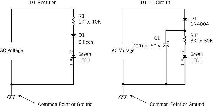
FIGURE 6.23 Two examples of using a “half wave” rectifier D1 to ensure that the LED does not experience any reverse bias voltage from the AC voltage source.
When using a peak hold capacitor, as shown in the “D1C1” circuit in Figure 6-23, be sure to increase the resistance value for R1 by about 3 times. The reason is that the average DC voltage at the positive terminal of C1 is higher than the half wave rectifier D1 circuit by about threefold. Thus, we see that the D1 C1 circuit’s LED current-limiting resistor R1" = 3KΩ to 30KΩ, versus R1 = 1KΩ to 10KΩ in the circuit on the left side “D1 Rectifier.”
Alternatively, one can connect an LED or diode in “counter” parallel to the LED as shown in Figure 6-24 to safely limit the reverse LED voltage. Note that the protection LED2 is connected with its cathode to the anode of LED1. In the D1 protection diode example, D1’s cathode is connected to the anode of LED1, and D1’s anode is connected to LED1’s cathode. In either example, the reverse bias voltage is limited to about –2 to –3 volts via LED2, and –0.7 volts via D1, which are both safe reverse bias voltages for LED1.

FIGURE 6.24 Two examples of protecting LED1 via LED2 and D1 wired in “anti-parallel.”
It should be noted that in Figure 6-24 LED2 lights up only during the negative cycle of the input AC voltage, and LED1 turns on only during the positive cycle of the AC voltage. This circuit can be used to identify the polarity of any incoming voltage. For example, if the AC voltage source is replaced with a DC voltage, the two LEDs “anti-parallel” circuit will readily identify the polarity.
On the left-side circuit of Figure 6-24, LED2 can be any type of LED, such as IR (infrared), red, green, yellow, blue, or white.
And on the right-side circuit of Figure 6-24, D1 can generally be almost any diode including small signal, Schottky, or rectifier diode. If in doubt, just use a 1N4000 series rectifier (e.g., 1N4002).
Some Keys Points About Light Emitting Diodes
• Light emitting diodes (LEDs) can be damaged by excessive forward bias current. Normally, the LEDs are driven at about 20 mA or less using a current-limiting resistor or some other circuit. See Chapter 7.
• LEDs can also be damaged by reverse voltage by having a negative voltage from anode to cathode. If the negative voltage is limited to between 0 volts to –4 volts, this will be OK. An “anti-parallel” connected diode or LED can be used to protect the LED in question.
• Different color LEDs generally cannot be connected in parallel because their turn-on voltages are different, which will cause “current hogging” for the LED that turns on with the lowest voltage. For example, if blue and yellow LEDs are connected in parallel, almost all the current will go to the yellow LED. This is because a yellow LED has a turn-on voltage around 1.8 volts, whereas a blue LED requires a higher 2.4 volts.
• If you need to have matched turn-on voltage LEDs, purchase them on a tape, as shown in Figure 6-21.
This concludes Chapter 6. In Chapter 7, we will explore transistors, where they can be used as current source and amplifying devices.