APPENDIX A
![]()
Choosing Test Equipment
Lab Power Supplies (Adjustable)
When purchasing a power supply we have to pay attention to whether it is a switching type or linear version. Switching power (switch mode) supplies are lighter than linear ones by a factor of at least two to one. For example, a 0- to 30-volt 10-amp switching supply weighs less than 4 pounds whereas a linear 0- to 30-volt 5-amp supply weighs about 12 pounds. See Figure A-1.
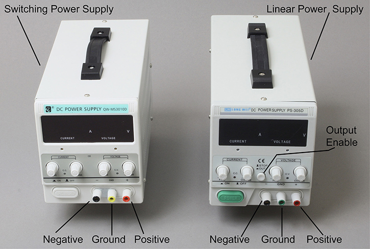
FIGURE A-1 On left side, a 10-amp switching supply such as the QW QW-MS3010D; and on the right side a 5amp linear version such as the LW Long Wei PS-305D, Lavota BPS-305, or Dr. Meter PS-305DM. Both supplies are adjustable from 0 to 30 volts.
Both supplies can be adjusted for an output voltage of 0 to 30 volts, and allow for setting the current limit for safety. To adjust for current limiting, initially turn the current limit knob fully counterclockwise, which will set the current to zero. Then turn the voltage knob about halfway. Temporarily connect a wire across the negative and positive binding posts. You can now slowly turn up (e.g., clockwise) the current limit knob to your desired maximum current limit such as 100 mA. Remove the wire across the negative and positive binding posts.
The supplies show three terminals, negative, ground, and positive, which allows the supply to be a floating voltage source (e.g., think of a battery) not connected to ground when only the negative and positive terminals are used. To have a positive voltage source with respect to ground, connect a wire from the negative terminal to the ground terminal. And to provide a negative voltage source with respect to ground, connect a wire from the positive terminal to the ground terminal.
One note of caution, the switching power supply shown in Figure A-1 (left side) has slightly smaller diameter binding posts, which do not appear to accept standard banana plugs from the United States. But the linear supply in Figure A-1 (right side) has standard binding posts and there were no problems using standard banana plugs including double banana plug connectors.
Although both supplies in Figure A-1 look and cost (approximately $55 US) about the same, they are not. For almost all purposes, it’s better to use the linear supply that measured with very low ripple/noise output, typically < 3 millivolts peak to peak, and a CV ripple rating of ≤ 1 mV RMS (root mean square).
However, the switching power supply is not desirable for working with analog circuits. The output ripple noise can be very high in the order of a few hundred millivolts to about a volt peak to peak. If we measure the noise from the switching supply of Figure A-1, we will see high amounts of noise. See Figure A-2, which shows the noise/ripple voltage from the QW model QW-MS3010D switching power supply.

FIGURE A-2 Ripple from the switching power supply set to 12 volts DC from Figure A-1, where the ripple voltage is at least 1 volt peak to peak given the 200 mV/div scale.
As we can see in Figure A-2, the ripple noise looks like a high-frequency carrier (measured around 60 kHz, the switching frequency) that is amplitude modulated by a low-frequency signal with about an 8-millisecond period that translates to 120 Hz. Although the peak-to-peak voltage is high at over 1 volt, the RMS (root mean square) noise voltage will be much lower. For radio frequency work, a switching power supply is not recommended due to its excessive noise.
To identify a switching power supply, look for the “CV” ripple rating. If it is in the 10 mV RMS range it is likely to be a switching supply. In contrast a linear supply will typically have ≤ 1 mV RMS of CV noise or ripple. Also if the shipping weight is about half the weight of a comparable or even half amperage linear power supply, most likely again it’s a switch mode power supply. For example, in Figure A-1 the weight of the switch mode (0–30 volts, 10 amps) is about 5 pounds whereas the linear version (0–30 volts, 5 amps) weighs about 12 pounds. One key word to look out for is “linear” when buying a power supply.
For general lab work, it’s better to have a dual or triple linear power supply. You can typically purchase new ones at about $150 to $200 US. However, it is possible to order a used or refurbished analog/linear power supply such as an older Instek GW GPC-3020 triple power supply (two independent 0–30 volts at 2 amps, one fixed 5-volt floating supply at 3 amps, and it weighs 17 pounds). See Figure A-3.
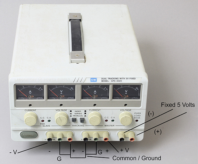
FIGURE A-3 A linear triple power supply bought used for less than $100 US. Example connection shown to provide +V and –V referenced to ground and a floating 5 volt source that can be configured as a +5-volt supply when its (–) terminal is connected to a ground terminal, G.
Most double or triple supplies will be linear types and will weigh in the 15- to 30-pound range. For example, you can purchase a new linear dual supply with two adjustable 0- to 30-volt supplies or a linear triple supply with 0– 30 volts and a fixed voltage supply.
For purchasing a linear supply, look for the telltale clues: > 15 pound weight, low CV ripple noise rating ≤ 1 mV RMS, and the word “linear” in its description.
Today many linear supplies include fans to reduce their heatsink size, which can be noisy sound-wise. However, you can find a new supply with a giant heatsink and no fan, such as the triple supply Dr. Meter HY3005-3, dual 0– 30 volts at 5 amps with a fixed 5-volt, 3-amp output for about $200 US.
Also, you can also get an older supply without a fan as the Leader LPS-152, which delivers 0–25 volts at 1 amp and 0–6 volts at 5 amps refurbished for under $200 US, but make sure there is a warranty just in case. Other older, quieter linear supplies include the ones made by Lambda and Hewlett Packard (HP).
Signal Generators
You can purchase inexpensive general purpose signal generators at relatively low prices below $100 US. If you want higher performance, there are excellent signal generators in the $250 to $500 range. See Figure A-4 where these generators use Direct Digital Synthesis (DDS) technology to deliver almost any type of waveform with very stable and accurate frequency.

FIGURE A-4 On the left side, JDS6600, a relatively inexpensive two-channel DDS signal generator (approximately 100 USD), and on the right the Siglent SDG2042X, a very high-quality, two-channel generator at about 500 USD. Note that the JSD6600 also includes a precision frequency counter via its Ext. In BNC connector so that you can measure the frequency of a signal.
Both generators are crystal-controlled and provide two independent signals with the frequency accuracy of a crystal oscillator (e.g., < 0.01 percent frequency tolerance).
The JPS-6600 sometimes goes by other names such as KKmoon, Koolertron, or Dominty. You can buy it in versions of 25 MHz to 60 MHz with increasing prices. This generator works well in delivering two independent channels of signals, or they can be “tied or synchronized” together such as providing I and Q signals (0 and 90 degree signals) of the same frequency. Sine wave harmonic distortion is about 0.50 percent, so it may not be suitable for evaluating high-fidelity amplifiers. But you can add a low-pass filter (e.g., three-pole filter) to lower the distortion.
For very high performance the Siglent SDG2042 works very well and its sine wave distortion is typically < 0.05 percent.
Both generators will provide various signals such as sine, square, triangle, pulsed, and arbitrary waveforms. In addition they will generate modulated signals including AM (amplitude modulation) and FM (frequency modulation), and other modulated waveforms.
One note to pay attention to: If the output resistance/impedance/Z is set to 50Ω, then this means that the amplitude you set will be twice the amplitude when loading into a high-impedance load such as ≥ 100kΩ, and will be the correct voltage when the generator is loading into 50Ω. For example, if you set the amplitude for 4 volts peak to peak, the generator will deliver 4 volts peak to peak into a 50Ω load, but will give 8 volts peak-to-peak open circuit. This has been the standard for most generators made by HP (Agilent, Keysight), Leader, Siglent, and others.
For a lower-cost generator, such as the JDS6600 in Figure A-4 or the higher performance FY6800 (not shown), it follows a nonstandard convention. If you set the output Z (resistance) to 50Ω and set the amplitude to 5 volts peak to peak, the output voltage will be 2.5 volts peak to peak into 50Ω, and 5 volts peak to peak into an open circuit.
These generators have many features so you will need to read their instruction manuals.
Oscilloscopes
Probably one of the most useful troubleshooting instruments you can purchase in addition to a digital voltmeter (DVM) is an oscilloscope. It measures voltage as a function of time. This is useful, for example, in tracing sine wave signals at various inputs and outputs of an amplifier. It for instance can tell you where the test signal “disappears” in a circuit. There are two types of oscilloscopes—analog and digital.
The analog oscilloscope is very easy to operate compared to the menu-driven digital scope. For troubleshooting analog circuits, the analog scope will more than suffice. However, only a few manufacturers are selling them new.
The classic analog dual trace Tektronix 465 and 475 are still among the best to use for troubleshooting analog circuits. These Tektronix scopes include a Channel 1 vertical output signal via a BNC connector that drives 50Ω input test equipment such as an RF spectrum analyzer. This way you can probe the circuit on Channel 1 with a high impedance probe (e.g., 10 Meg Ω) while observing the frequency spectrum via a spectrum analyzer of the (time domain) signal displayed on the oscilloscope. Note that if you connect the 50Ω input of the spectrum analyzer straight to parts of your circuit, you will most likely load down the signal or cause an oscillator circuit to stop oscillating.
Digital oscilloscopes in 2019 are relatively inexpensive compared to those sold in the 1990s (e.g., > $2,000 US). A good lab version costs about the same as a high-end DVM (approximately $250 US). See Figure A-5 with three 2-channel versions.
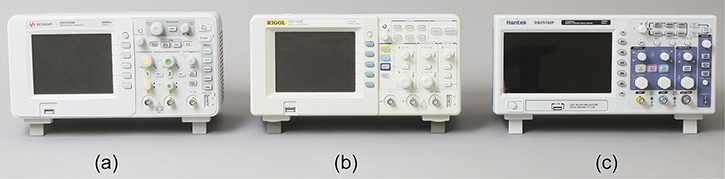
FIGURE A-5 Three digital oscilloscopes: (a) Keysight DSO1052B 50 MHz (approximately $300); (b) Rigol DS1102E 100 MHz (approximately $300); (c) Hantek DSO5102P 100 MHz (approximately $260).
Two 4-channel digital oscilloscopes that can be very handy for troubleshooting analog and digital circuits are shown in Figure A-6. These have 480×800 displays and ≥ 12M memory points (pts).

FIGURE A-6 Two 4-channel digital oscilloscopes: (a) Rigol DS1054 50 MHz (approximately $375); (b) Siglent SDS 1204X-E 200 MHz (approximately $760).
Some of the main features to look for in a digital storage oscilloscope (DSO) are:
• A 100 MHz bandwidth is good enough for most purposes. If you are troubleshooting RF circuits, you may need ≥ 200 MHz bandwidth. For the beginning hobbyist, a 50 MHz oscilloscope will work very well. Note all oscilloscopes will still respond to at least another 20 percent higher than its rated bandwidth, but the waveform displayed at these frequencies will not be accurate amplitude-wise due to a roll-off in high-frequency response. For example, a 50 MHz oscilloscope can usually still display a 60 MHz or 100 MHz signal, but with some attenuation.
• Display resolution. The smaller display oscilloscopes, such as the Keysight DSO1052B and older Rigol DS1102E, have a 240×320 pixel display, which reproduces waveforms in a stepped manner. The Hantek DSO5102P, Rigol DS1054, and Siglent SDS 1204X-E have 480×800 pixels that will display a smoother, more analog-like waveform.
• Number of points stored, which can be as low as 16 thousand and as high as > 14 million. For critical work, go for at least 100 thousand points. Preferably, ≥ 1 million points will work very well.
Examples of Display Resolution and Number of Memory Points
Let’s take a look at Figure A-7, which shows imperfect sine wave reproduction due to display limitations and limited memory (Keysight has 32K points and Hantek has 40K points). Note: pts = points.

FIGURE A-7 Keysight with 240x320 pixels (32K pts); Hantek with 480x800 pixels (40K pts).

FIGURE A-8 Rigol 480x800-pixel display but with 12M points gives a better looking waveform.
As we can see in Figure A-8, the number of pixels and memory depth (e.g., number of memory points) really makes a difference in displaying a waveform with fidelity. We can also look at an analog oscilloscope’s display of this waveform in Figure A-9.
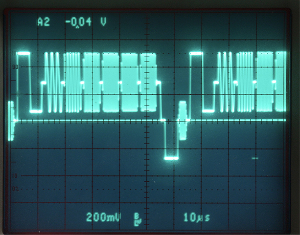
FIGURE A-9 A Tektronix analog oscilloscope shows a really clean display of the test signal. Note the lack of “jaggies” when compared to Figures A-7 and A-8.
NOTE: The test signal is a video multiburst signal starting with one cycle of squarewave, then followed with sinewave packets at increasing frequencies of 0.5 MHz, 1 MHz, 2 MHz, 3 MHz, 3.58 MHz, and 4 MHz.
When a digital oscilloscope has less than 100K memory points, it will generally display the waveform with aliasing problems due to insufficient sampling points of the waveform.
If we take the same test signal and slow down the horizontal sweep from 10 μsec/div (or 8 μsec/div) to 200 μsec/div we see the oscilloscope with the most memory points reproduces the waveform more correctly. See Figure A-10 where the waveforms are stored at 200 μsec/div.

FIGURE A-10 From left to right: Rigol (12M points), Hantek (40K points), and Rigol (32K points), and all three oscilloscopes are set to the “Stop” mode to store the waveform. Only the Rigol (on the left side) with 12 million memory points seems to display the test signal properly at 200 μsec/div. The other two have random gaps in the waveform that are caused by sub-Nyquist sampling.
We can zoom in or magnify the stored waveform by setting the horizontal sweep to 20 μsec/div. See Figure A-11.
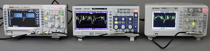
FIGURE A-11 Zooming into the waveform with 20 μsec/div, we see that only the Rigol on the left side reproduces the test waveform correctly. The Hantek is in the center.
As shown in the Rigol oscilloscope, the waveform is reproduced accurately with each sinewave packet increasing in frequency. See Figure A-11 above. However, we see with the 40K point Hantek, the test signal looks distorted in that we do not see sinewave packets increasing in frequency and the waveform is replaced with a pulse or a lower-frequency triangle wave.
In Figure A-12, the Rigol oscilloscope is the most expensive compared to the Hantek and Keysight. So this comparison is not taking into account the cost.
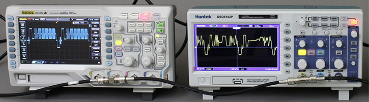
FIGURE A-12 A closer comparison between the $375 12M point 50 MHz Rigol DS 1054Z (on the left) and the 100 MHz $260 40K point Hantek DSO5102P (on the right).
Fortunately, Hantek and Keysight make oscilloscopes with more memory points, such as the 100 MHz, 1M pt Hantek DS5102B ($359), or the 70 MHz, 1M pt Keysight DSOX1102A ($563) with higher-resolution display (compared to the 50 MHz Keysight DS1052).
Note that all digital oscilloscopes also include a set of built-in measurement functions such as an FFT spectrum analyzer, peak-to-peak voltage, frequency, pulse width, etc. Thus, it is important to read through the operating manual.
Oscilloscope Probes
You will need to use oscilloscope probes to monitor/measure various nodes of your circuit. In general, you should use a 10× probe for lowest capacitance loading (e.g., 10 pf to 20 pf, depending on the make and bandwidth).
NOTE: Sometimes the probes are named x1 or 1x and x10 or 10x.
Most fixed 10× probes have a bandwidth specification of 100 MHz or more, and they have typically a tip-to-ground lead capacitance of 10 pf to 15 pf. The load resistance will be 10MΩ when connected to an oscilloscope’s BNC connector. A 10× probe actually attenuates the signal you are probing by 10-fold. For instance, if you are monitoring a 10-volt signal with a 10× probe, the oscilloscope will receive only 1 volt at its BNC input connector. Although there is attenuation, you have the advantage of essentially not loading the signal with your 10× probe. This is particularly important when troubleshooting high-frequency or high-impedance circuits.
In Figure A-5, fixed 10× probes are standard accessories for Keysight oscilloscopes.
When you buy a new oscilloscope today such as one from Hantek, Rigol, or Siglent, most likely they will supply you with switchable 1×/10× probes. See Figure A-13.
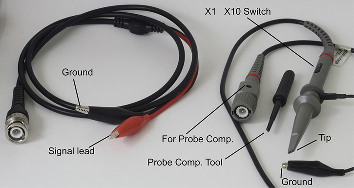
FIGURE A-13 A coaxial cable on the left, and a X1/X10 probe on the right with a probe compensation tool.
NOTE: The cable or probe’s ground lead connects to the circuit’s ground.
The coaxial cable in Figure A-13 is an inexpensive way to connect to your oscilloscope, is the same as a X1 probe with about 100 pf capacitance, and will have a 1MΩ load resistance via the oscilloscope’s BNC input. Generally, we should avoid using the coaxial cable when working with high-frequency or high-impedance circuits. You can use them but just remember that the cables may load down your signal. For example, measuring with a coaxial cable (or with a X1 probe) may make your circuit appear worse in high-frequency response than it really is.
The switchable X1 and X10 probe acts pretty much like a coaxial cable when switched to the X1 setting (approximately 80 pf to 150 pf capacitance and 1MΩ resistance), while in the X10 mode it has an 11 pf to 20 pf load capacitance and 10MΩ load resistance.
Also shown in Figure A-13 is a small flat blade tool to adjust for probe compensation (comp.), which is a procedure for only 10× probes. The ×10 probe is connected to a squarewave calibration signal supplied in the front panel of the oscilloscope. Via a hole at the BNC connector (or at the probe), you adjust with the tool until the oscilloscope displays a “perfect” squarewave without rounding in the corners or without overshoot. Each probe you use must go through the probe compensation adjustment; otherwise, the frequency response you are measuring with an uncompensated probe will result in a non-flat frequency response that will cause measurement errors.
An Inexpensive Lab
If you are on smaller budget (< $100), you can actually buy an analog signal generator for less than $10, an oscilloscope in the $14 to $66 range, and a DC wall charger/power supply in the $10 range. See Figure A-14.
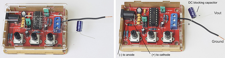
FIGURE A-14 A < $10 generator kit. Generator with supply protection diode.
You need to assemble this analog signal generator kit with a soldering pencil and wire cutters. Also, you need a power supply in the 10 volts to 18 DC range with the ground/sleeve portion labeled as the minus terminal (–) and the tip of the power connector (2.1 mm) marked as the positive terminal (+). A protection diode was added just in case the power supply is connected with wrong polarity. Also, a DC blocking capacitor (e.g., 100 μf 25 volts) was added because the output terminals have large DC offset voltages > 1 volt DC.
If you need a 1-channel oscilloscope that will work with low-frequency projects such as audio amplifier or circuits at < 50 kHz, there is an inexpensive $14 to $20 oscilloscope that requires a 9-volt DC power supply. Also, you can buy an oscilloscope with a rechargeable battery (via USB connector) for about $40. These oscilloscopes are not recommended for serious troubleshooting but can come in handy out in the field when you have limited space. See Figure A-15, which shows two oscilloscopes or o’scopes.
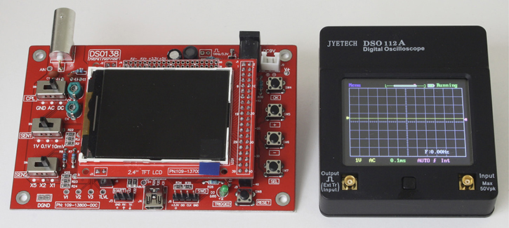
FIGURE A-15 A $14 o’scope on the left, and a $40 rechargeable battery version on the right.
There are also USB oscilloscopes with two channels available from about $66 and up (e.g., the 20 MHz, 1M pt Hantek 6022BE), but you need a computer to display the waveforms. See Figure A-16. While a USB o’scope can be useful for troubleshooting out in the field, it may not have the high analog bandwidth or enough memory to compete with a lab oscilloscope such as one with a 200 MHz bandwidth and 14M points. Also, it is generally easier to use a lab scope with its knobs rather than using a USB oscilloscope with a computer’s cursor.
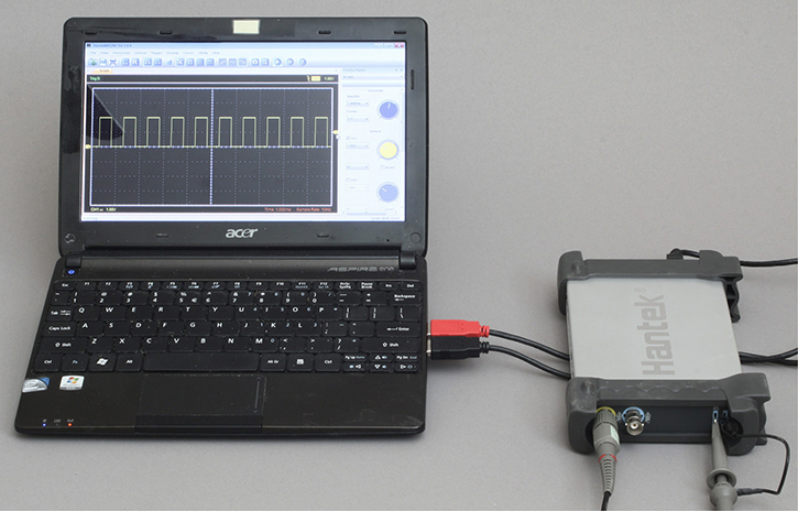
FIGURE A-16 A Hantek 2-channel USB oscilloscope with a 10-inch laptop computer.