CHAPTER 5
Server Network Communications
In this chapter, you will
• Learn about the OSI model
• Identify proper cable installation and management techniques
• Recognize the role of network interface cards, switches, and routers
• Learn how to configure IPv4 and IPv6, including subnetting
• Understand TCP and UDP port numbers
• Identify network infrastructure services, including DHCP, DNS, and WINS
Every server technician is exposed to networking at the hardware and software levels at some point in time. You may not be the network infrastructure expert in your organization, but your servers will interface with the network infrastructure in various ways. The TCP/IP protocol suite has long been used on corporate networks as well as the Internet. As such, Server+ candidates are required to have a solid understanding of both IPv4 and IPv6.
The OSI Model
Telephony and network communications involve both hardware and software components. The Open Systems Interconnection (OSI) model is a widely accepted seven-layer approach to mapping and explaining these components. The IT industry will often refer to “Layer 3 switches,” “Layer 7 firewalls,” “Layer 2 addresses,” and so on.
The OSI layers are not tangible or visible in any way; they are a concept, albeit an important one. Not all layers need to be involved in the transmission and receipt of data between two devices, and not all network protocols map cleanly to OSI layers.
Here are the seven layers of the OSI model:
• Layer 7 Application layer
• Layer 6 Presentation layer
• Layer 5 Session layer
• Layer 4 Transport layer
• Layer 3 Network layer
• Layer 2 Data link layer
• Layer 1 Physical layer
One way to remember the seven layers, starting from the top, is by using a mnemonic: “All People Seem To Need Data Processing.” Table 5-1 explains the characteristics of each layer.

Table 5-1 OSI Layers
Let’s apply the OSI model to the action of viewing a secured web site (HTTPS) using a web browser. Bear in mind that not all protocols such as Transport Layer Security (TLS) fit cleanly into individual OSI layers.
1. The user enters an HTTPS Uniform Resource Locator (URL) into the address line of a web browser. The application layer (7) is involved at this point.
2. Because an HTTPS connection is being used, the presentation layer (6) is involved due to encryption. TLS is commonly used as the network security protocol instead of the deprecated Secure Sockets Layer (SSL) protocol.
3. HTTPS establishes a session with the receiving host before transmitting data, so the session layer (5) is used here.
4. TCP is a transport layer (4) protocol. Layer 4 addresses are port addresses; HTTPS web servers normally listen for client connections on TCP port 443.
5. If the client and server are on different networks, a router gets involved. Routers are Layer 3 (the network layer) devices. IP addresses would still be involved even on the same network, and IP addresses are Layer 3 addresses.
6. On the LAN, Media Access Control (MAC) addresses (hardware addresses) are used. This applies to the data link layer (2), as does the specific mechanism for gaining access to the transmission medium.
7. Finally, the physical layer (1) is involved whether a wired or wireless connection is used for connectivity.
8. The same type of activity takes place on the other end of the connection, but instead it moves up the applicable layers of the OSI model.
Cable Installation and Management
Wireless networking in the form of cellular 4G, 5G, and Wi-Fi communications has exploded in popularity for user devices. But for servers and infrastructure equipment in the enterprise, data center, and server room, wired networking is more common than wireless. Many organizations use a hybrid of both wired and wireless communications, and these apply to the physical layer (1) of the OSI model.
Cable Placement
Large server rooms and data centers use racks to mount equipment—but what about all the power and data cables? Power cables for equipment are normally located in the back of the rack, as are network cables for servers, storage arrays, KVM (keyboard, video, mouse) switches, and the like. Cable management arms can be used to organize cables for rack-mounted devices. As the rack-mounted device is slid out on a rail, the arm containing the cables expands, so we don’t have to worry about cables being pulled tight.
In the case of rack-mounted network switches and similar equipment, network cables are plugged into ports on the front of the equipment. Either way, we need an organized way to channel these bundles of cables both horizontally and vertically using cable management trays or channels built into the rack.
Plastic cable ties and hook-and-loop fasteners can be used to keep bundles of network cables together. These bundles are fed into cable channels, which can be built into racks or added to existing racks. The cable channels can also extend from racks to other locations in the server room or data center as required.

CAUTION Cable channel placement, especially near ceilings, must be carefully planned. You don’t want thick bundles of cables and cable trays hampering the effectiveness of fire suppression systems or airflow mechanisms.
Cable Labeling
Most people like spaghetti, but not in server rooms. Dealing with bundles of unlabeled knots of network cables is not so great; check out Figure 5-1 to see what I mean. Have you ever had to trace network cables in a server room or wiring closet? It can go one of two ways:

Figure 5-1 A mess of network cables
• A good experience because of labeling and proper cable management
• A frustrating experience because of a snake pit of tangled cables
Network wall jacks, as well as the other end of the cable on the patch panel in the server room or wiring closet, need to be correctly labeled. From the patch panel, shorter network cables are plugged into network equipment such as Ethernet switch ports. These patch cables also must be correctly labeled.
You must establish and follow a labeling standard. Using things such as IP addresses or computer names for labeling isn’t a great idea, because they are both easily changed. You might use a wall-jack labeling scheme or a location-based scheme (Floor 9, Room 2, Jack 1 might become f9r2j1). Or you might simply use incrementing numbers (jack1, jack2, jack3, and so on). Printing these values on small stickers or cable labels makes your life much easier when you’re tracing cables and troubleshooting. Recording this on a network or building map can also be helpful. Color-coded cables can also make your life easier. For example, you could establish a standard that cables plugged into infrastructure equipment such as switches and routers will all be colored orange.
Cable Types
There are many different types of network cables, but regardless of your choice, cables must be properly organized and labeled. When you’re routing cables around corners, make sure you don’t exceed the cable bend radius, which determines the degree to which you can bend a cable without damaging the wires inside it. For example, for CAT5 and CAT6 network cables, the bend radius is four times the diameter of the cable—this works out to be about 1 inch. Fiber-optic cables, on the other hand, have a bend radius of about 2 inches.
Several questions need to be addressed to determine cable selection criteria, including the following:
• What type of connectors does our equipment support?
• Over what distance must the transmission travel?
• Could electromagnetic interference (EMI) be a problem?
• Can eavesdropping be a problem for cable transmissions?
Copper Cables
Copper cables contain copper wires that transmit electrical signals. Shielded twisted pair (STP) and unshielded twisted pair (UTP) cables contain eight copper wires grouped into four pairs. Each pair of wires is twisted at a specific rate to reduce crosstalk interference from adjacent wires. The higher the transmission rate (higher frequencies), the greater the number of twists per inch. Figure 5-2 shows a UTP cable.
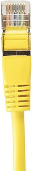
Figure 5-2 UTP cable with RJ-45 connector

NOTE Network cables alone do not determine how quickly data is transmitted. Other factors, including network card and switch port configuration, as well as distance covered, greatly influence network speeds.
STP cables have a shielding layer that sends interfering electronic signals to a ground wire that protects signals being transmitted within the cable. UTP does not have a shielding layer so it is more susceptible to EMI produced from objects such as machinery in a manufacturing plant.
Copper Cable Connectors RJ-11 connectors are used for standard four-wire telephone cables. RJ-45 connectors are used for UTP and STP cables. These connectors are plastic with tiny metal plates that connect to the copper wires in the cable, thus allowing for electrical conductivity when plugged into an RJ-11 or RJ-45 socket. RJ-45 connectors are shown in Figure 5-3.
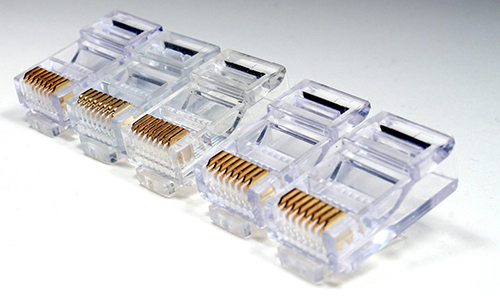
Figure 5-3 RJ-45 connectors
Modern office phone systems use the Voice over Internet Protocol (VoIP), where each phone is a node on the network with a unique IP address. Older office phone systems used physical private branch exchange (PBX) devices or PBX virtual machine appliances. PBX is used for internal office phone systems; you can configure extension numbers (the office would need only a single public telephone number), hold music, voicemail settings, call forwarding, and a full complement of telephony options. Back in the day, RJ-11 connectors linked office phones to the PBX.
Common Copper Cable Uses When the eight copper wires in a network cable are in the same position at both ends (the pin 1 wire on one end corresponds to pin 1 on the other end of the cable), we have a straight-through cable. This is the most common type of copper-based network cable; we use it to plug stations into network wall jacks, to connect patch panel connections to switch ports, and to interconnect network infrastructure equipment such as switches.
Crossover cables reverse the receive and transmit wires on each end of the cable. We can use this to plug stations directly into each other without a switch, or, if required, we can use these to link equipment together such as switches. Most modern network switches don’t require crossover cables; they can automatically detect whether a straight-through cable is being used and properly match the other end of the link.
Rollover cables are used for administrators to connect locally to network equipment such as the console port on a router. These are easy to identify: the cable is flat and is normally light blue in color. But don’t depend on cable color to indicate the cable type; instead, look at the connectors and the wire-to-pin layout in the connector.
CAT5, CAT5e, CAT6 Copper cable categories are distinguished from one another by the transmission speeds they can accommodate at higher frequencies. This is accomplished by increasing the number of twists per inch for each wire pair. So the CAT5 network cable standard has more twists per inch than a CAT3 cable, which means CAT5 can transmit data at a much higher rate than CAT3. Remember that network cards and network equipment also factor into transmission speeds.
Copper network cables generally have a maximum transmission distance of 100 meters (328 feet), after which the signal degrades significantly. (You can multiply meters by 3 to get an approximation of the distance in feet.) Repeaters can be placed at every 100 meters to extend the distance of the network. A network switch or router can be used as a repeater. Table 5-2 shows the differences between copper cable types. Unless otherwise stated, it is understood that 100 meters is the maximum distance.
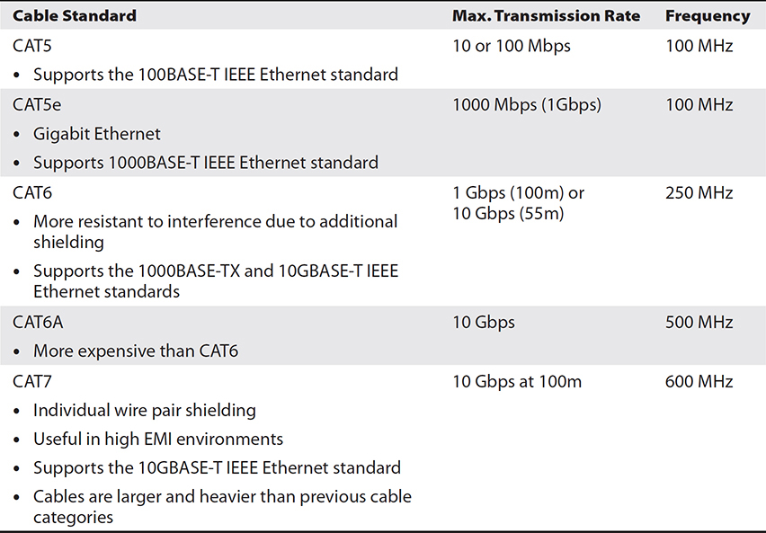
Table 5-2 Copper Cable Categories
NOTE Newer copper cable standards will work with older network equipment. This is useful when you’re upgrading cabling before upgrading equipment. The only issue is whether or not the existing equipment can transmit or receive at the rated speeds for the cable standard.
Fiber-optic Cables
Fiber-optic cables transmit light instead of electrical signals, so they are not susceptible at all to EMI. You need special network cards and equipment to transmit and receive data over fiber-optic.
Contrary to popular belief, the term “fiber-optic” does not always means faster transmission rates, although many vendors market it this way, such as FibreOP for the home. Fiber-optic cables enable signals to travel longer distances than their electrical counterparts because light can travel much farther than electrical signals before the signal degrades. For example, where twisted pair copper network cables generally max out at 100 meters, fiber-optic can travel hundreds of kilometers. Figure 5-4 shows a fiber-optic cable.
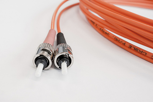
Figure 5-4 Fiber-optic cable with straight-tip connectors
Each individual glass or plastic core fiber in the cable can carry different light wavelengths, which means it can carry multiple signals over different channels. This is often used on service provider backbones and requires optical multiplexer and demultiplexing equipment.
Fiber-optic offers benefits such as the following:
• Multiple channels carried in a single fiber rather than requiring many copper network cables
• Not susceptible to EMI
• Lightweight, so it works well in places such as aircraft
• No possibility of sparks, so it’s good in explosive environments
• Difficult to eavesdrop (wiretap)
Fiber-optic cabling usage is not quite ubiquitous with desktop computer connectivity because of its cost, but it is commonly used for server networks and internetwork connections.
There are two general types of fiber-optic cabling: single-mode and multi-mode. Single-mode fiber (SMF) has a smaller diameter (less than 10 micrometers) than multi-mode fiber (MMF), about 50 micrometers in diameter. SMF supports greater distances, but this means that SMF is more expensive than MMF, which is useful for distances of less than 2 kilometers (1.2 miles). Bear in mind that a single fiber-optic cable could consist of more than one SMF core.
NOTE Imagine the great distance covered using submarine fiber-optic cables linking Halifax, Nova Scotia, to Dublin, Ireland—we’re talking 12,000 kilometers, or 7400 miles! Check out www.submarinecablemap.com/ to see undersea fiber links around the planet.
Fiber-optic Connectors Just as copper cables have their specific connectors, so, too, do fiber-optic cables. Table 5-3 lists common fiber-optic connectors, but bear in mind that SFP, SFP+, and QSFP (listed in the table) also support connections to copper cables.

Table 5-3 Common Fiber-optic Cable Connectors
Network Hardware
It takes varying pieces of network equipment working together to result in a functioning network infrastructure. This section gets into network interface cards, network switches, and routers.
Network Interface Cards
Network cables have connectors that are supposed to plug into something, and one of those items is a network interface card (NIC). Most modern computers have a wired NIC embedded on the motherboard; servers, including blade servers, often have multiple onboard NICs. Some blade server models enable a daughter circuit board (a NIC) to be plugged into the blade server motherboard.
You must carefully choose NICs to support your needs, which may include the following:
• Supports your network topology such as Ethernet, IEEE 802.11 wireless
• Includes the correct connector sockets such as RJ-45, fiber ST, SFP
• Supports the correct speeds such as1 Gbps, 10 Gbps Ethernet
MAC Address
All network cards have a unique 48-bit hexadecimal hardware address, also called a physical address or Media Access Control (MAC) address. Whether we work with Bluetooth or Wi-Fi wireless NICs or a wired Ethernet NIC, they all have a MAC address, which looks something like this: 90-48-9A-11-BD-6F.
NOTE On a Windows system, you can see the MAC address for your network interface(s) by typing ipconfig /all. On Linux, type ifconfig.
The MAC address is a hardware-unique identifier used only on the LAN. So, for instance, when you connect to an Internet web server, your machine must know the web server’s IP address, but it’s not concerned with the web server’s MAC address. You might wonder what role the MAC address then plays; in our example, your machine must know the MAC address of the router, or default gateway, to get traffic out of the LAN.
MAC addresses can also be used to control connections. One great example of this is MAC address filtering at the switch port level or with a wireless router; if your MAC address is not on the “allowed” list, you can’t connect. However, MAC addresses can be spoofed, or forged, so don’t rely solely on MAC address filters for security. MAC addresses are also called Layer 2 addresses.
Common NIC Features
Modern desktop and server motherboards often have integrated network cards. You can configure a series of options depending on how you plan on using the cards.
Wake-on-LAN One common NIC feature is Wake-on-LAN (WoL). WoL must also be supported by the BIOS or Unified Extensible Firmware Interface (UEFI). It enables a powered-down system to still feed enough power to the NIC so that it can be woken up remotely with a specially crafted packet. Although this can work well for desktops that you want to push updates to in the middle of the night, servers are generally left on all the time.
PXE The Preboot Execution Environment (PXE) NIC feature works with the BIOS or UEFI boot sequence to enable network boot. This means that instead of starting an operating system from a local disk, a small operating system image gets pulled across the network from a PXE boot server to local RAM. PXE boot works best with Dynamic Host Configuration Protocol (DHCP) to assign IP settings dynamically to PXE boot clients, and this is common as a server network imaging solution.
NIC Teaming NIC teaming is used to group multiple NICs together, similar to grouping multiple disks together in a RAID array. A NIC team can be used to aggregate the bandwidth of multiple NICs together for better performance, or it can be used for communications redundancy in case one NIC fails. You may encounter vendor terms such as “NIC bonding” or “NIC balancing”; it all falls under the same umbrella.
NIC teaming can be a function of a server operating system (such as Windows Server) and/or the network switch. NIC teaming configuration on the Windows platform is shown in Figure 5-5. If you were to configure NIC teaming for bandwidth aggregation in an operating system, network traffic leaving the server could take advantage of this feature, but not inbound traffic (how would the sending station or switch know about the NIC teaming?). You may have to involve your switch administrator to configure switch port aggregation for the switch ports your server NICs are plugged into.

Figure 5-5 Adding NICs to a NIC team using Windows Server
Network Switches
For wired networks, most modern network equipment uses twisted pair cabling to plug devices into wall jacks, which in turn use short patch cables to plug into switch ports in a wiring closet or server room.
For very small networks, a 4-port switch might do the trick. In larger networks, multiple 24-port switches may be linked (trunked) together to accommodate large numbers of devices. With most modern switches, a standard twisted pair straight-through cable can be used to link switches together, although you may come across some that require a crossover cable (receive and transmit wires are reversed on either end of the cable). Higher end switches will use fiber-optic cabling to link together, or trunk, switches through fiber or SFP ports.
VLANs
By default, all physical switch ports are configured within the same virtual local area network (VLAN). A VLAN is a way of grouping devices together so that they can communicate as if they were on the same physical LAN. A router is needed for devices on different VLANs to communicate. Layer 3 switches have built-in routing capabilities, so it’s convenient to configure inter-VLAN routing using a single device.
A VLAN may simply group physical switch ports together. For example, switch ports 1–12 may be called VLAN1 and switch ports 13–24 may be called VLAN2. Even though all ports are physically on the same switch, without a router, a device on VLAN1 will not be able to communicate with a device on VLAN2.
Another way to create a VLAN is by having the switch examine the IP address of the device plugged into the port. For example, regardless of physical port, devices plugged into the switch with a network prefix of 172.16.0.0 would be considered to be on the same VLAN, so they can talk to each other without requiring a router.
Switch administrators can also control VLAN membership by MAC address, by protocol used on the client device, and by higher level applications in use. So a device with a MAC address of 90-48-9A-11-BD-6F could be configured to be in VLAN1. As another example, devices using File Transfer Protocol (FTP) could be grouped together into their own VLAN.
Network people normally configure VLANs to improve network efficiency. Having a number of devices that talk frequently on their own small network instead of everybody on a large network makes sense. Creating a VLAN creates a new broadcast domain. Broadcasts are network transmissions addressed to all devices on the network; they don’t cross VLANs, so multiple VLANs can reduce traffic overall.
Another primary reason for multiple VLANs is security; accounting devices may be placed on a separate VLAN from the rest of the network, for example.
Layer 2 and Layer 3 Switches
Most switches are Layer 2 devices because they work with MAC addresses. Higher end switches will have IP routing capabilities and are Layer 3 switches.
A switch has its own memory, where it tracks which device MAC addresses are plugged into its ports. This is done so that, instead of broadcasting transmissions to every port (like a hub does) to find a specific MAC address, it simply consults its MAC address table in memory. This reduces network chatter and essentially creates a collision domain for each switch port. Why does this matter? Unlike a hub, switches enable multiple concurrent network conversations.
The cheapest, least functional switches are not manageable. This means you supply power to the switch, plug devices into the switch ports, and that’s it—you can’t configure it any further, and you certainly can’t connect to it over the network for management purposes. Figure 5-6 shows a UTP cable with RJ-45 connector plugged into a switch port. Most enterprises use managed switches that are assigned a valid IP configuration so that various remote management tools such as web browsers and SSH can be used by administrators to connect remotely over the network.
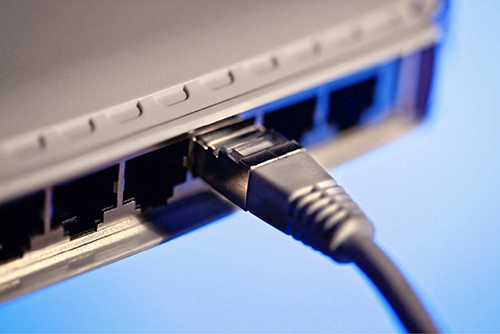
Figure 5-6 A UTP cable plugged into an Ethernet switch port
The following list includes common items you could configure on a switch:
• Port duplex mode and speed
• VLANs
• Disabled (unused) switch ports
• TCP/IP settings (for managed switches)
• Port aggregation (for NIC teaming)
• Port multicast support
Routers
Routers have at least two interfaces that interconnect networks. A large company may use dozens of routers to interconnect its internal networks. The Internet, in fact, consists of millions of interconnected routers.
A router has memory that stores routing tables. Routers use routing protocols such as Routing Information Protocol (RIP) and Open Shortest Path First (OSPF) to exchange routing information with one another.
To look up the best way to send packets to a remote network, routers consult their routing tables, which include information about other IP networks and characteristics (routing metrics) such as the route cost, how many hops (routers) the packet would have to go through before arriving at its destination, and other details.
Because it deals with IP addresses and transferring network traffic to remote networks, a router is said to be a Layer 3 device. Remember that Layer 3 of the OSI model is the network layer.
Figure 5-7 shows a router with three interfaces. Interface 0 is public-facing with a connection to the Internet. Interfaces 1 and 2 each connect to a separate internal network switch where other network devices such as printers, desktops, and servers would be plugged in. Each router interface must be configured with the correct TCP/IP settings.
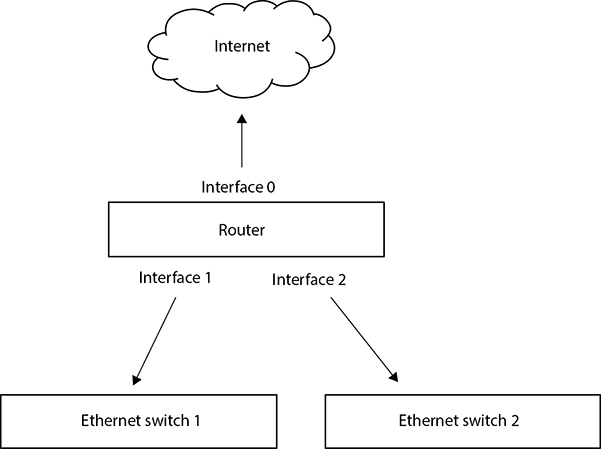
Figure 5-7 A simple network infrastructure
Configuring IPv4
We all know how old-school telephones work. With a local number, the first three numbers identify the local exchange or central office, and the last four numbers identify a specific telephone. IP addresses work similarly, where a single IP address consists of both a network and node (host) portion.
For communication on today’s enterprise networks (and the Internet), devices must have a unique IP address—unique, at least, on their LAN or subnet. Have you ever wondered why, for example, you can use an IP address of 192.168.1.100 on your home network, and your friend on her home network can use the same IP address? How does that work if you can both get on the Internet? The answer is Port Address Translation (PAT).
PAT
Port Address Translation enables many internal IP addresses to connect through a PAT router to the Internet using a single public IP address (the one assigned to the public interface of the PAT router). The PAT router uses a unique source port number from the internal sending machine to track external connections and their responses. This works well to get a bunch of internal devices on the Internet with a single public IP address. When most people refer to NAT, they’re really talking about PAT.
You can check out your Internet IP address from home or work on different devices (including smartphones and tablets) by visiting www.whatismyip.com. You’ll see that all your internal devices appear to be coming from the same IP address. Figure 5-8 illustrates how many internal IP addresses can get to the Internet using a single public IP address by tracking port numbers.

Figure 5-8 PAT router port table
Static NAT
Static NAT maps external IP addresses on the NAT router to corresponding internal IP addresses for devices on the internal network. This is useful when you want to allow inbound connections to hosts on a private network through a NAT router while hiding the true internal IP addresses of those hosts. So there is a 1:1 correlation between external and internal IP addresses.
IP
The Internet Protocol (IP) is a big deal. We hear about it all the time at work and in the media when the latest Internet hack spreads like wildfire. It is the specific TCP/IP protocol that enables traffic to shoot around the Internet, and it applies to Layer 3 of the OSI model.
Devices that want to communicate on a TCP/IP network must have a valid IP address (among other things), but IP is also responsible for routing packets to different networks all over the planet. Routers look at IP addresses to determine the best way to get traffic to a remote network efficiently. This applies to both IPv4 and the newer IPv6.
IPv4 Addressing
The swinging 1960s led to the initial development of standards for linking computers together, including software network communications protocols. This led to the creation of the ARPANET in October 1967, which was funded by the US government, but designed and implemented by various research and academic folks. Depending on which folks you talk to, either those who were involved in the research funding or those involved in the actual research and implementation of the ARPANET—you’ll get a different explanation as to why the ARPANET was created. The designers will say it was created to enable a sharing network with no central authority, while U.S. government officials who signed the checks will say it was to create a distributed network that could still function in the event of a nuclear attack. Either way, we’re all grateful that the ARPANET evolved into the Internet that we all know and love today!
An IPv4 address is 32 bits long, but most of us are used to seeing it expressed in decimal with a period separating each 8-bit group, such as 192.168.1.1, the binary equivalent of which is 11000000 10101000 00000001 0000001. Each grouping of 8 bits is called a byte or octet.
Since we’re working with binary 0’s and 1’s, the smallest possible value for an octet is 0 (00000000 in binary) and the largest is 255 (11111111 in binary), so you’ll never see an IPv4 address like 267.3.52.378—mathematically, it’s not possible. IP addresses are also referred to as Layer 3 addresses.
NOTE Many organizations use specific internal IP ranges for certain types of devices. For instance, servers may always be configured in the 200 to 210 host range, and network printers may be in the 220 to 230 host range. So if your IPv4 network prefix is 192.168.1, the first server IP address would be 192.168.1.200 and the first network printer IP address would be 192.168.1.220.
Subnet Mask
Earlier in the section we stated that a single IP address consists of both network and node (host) portions. The subnet mask defines this. For example, consider the following:
IP address: 192.168.1.1
Subnet mask: 255.255.255.0
The first octet of the subnet mask (255) means all of the binary bits are set to 1’s. This means this entire octet identifies a part of our network; the same is true for the next two octets. The result in this example is that the first three octets identify the network that the device is a member of, which is 192.168.1.0/24. A trailing 0 is normally used to identify a network address. The /24 (which is called CIDR, Classless Inter-Domain Routing, notation) means there are 24 binary 1 bits in the subnet mask, so /24 and 255.255.255.0 have the same meaning. That leaves us with one octet (the fourth octet) to address devices, or hosts, on the 192.168.1.0 network. The device address in this example is simply 1.
NOTE Many a wireless router has its internal WLAN IP address set to 192.168.1.1. In this case, either start using addresses from 192.168.1.2 onward or reconfigure the IP address of the wireless router.
Reserved Internal IP Address Ranges
The address 127.0.0.1 is a reserved local loopback address used for testing, but there are entire ranges of IP addresses designed for internal use on enterprise networks. These private IP address ranges are defined in RFC 1918 (https://tools.ietf.org/html/rfc1918). Internet routers don’t forward this type of traffic, but your organization’s internal routers can. The address ranges follow:
• 10.0.0.0–10.255.255.255
• 172.16.0.0–172.31.255.255
• 192.168.0.0–192.168.255.255
Public unique IP addresses are allocated by your Internet service provider (ISP), and depending on your needs, you could have only one or dozens of them. If, for instance, you wanted to host your own public web site on your own network, you would need a unique public IP address (and DNS name too).
An example of a public IPv4 address is 199.126.129.77. IP addresses can be configured manually, as shown in Figure 5-9. With IPv4, there is a shortage of addresses. Mathematically, 232 equals 4 billion and change. In other words, there are around 4 billion unique IPv4 addresses possible. This is where PAT, NAT, and IPv6 come in.
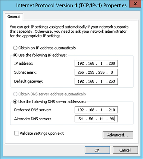
Figure 5-9 Manual configuring of IPv4 settings in Windows
When to Use Subnetting
There are times when you’ll have a single IP network address but more than one network to allocate IP addresses to. Other than acquiring additional network addresses, you can opt to subnet.
Subnetting takes an existing network address and subdivides it into subnetworks, or subnets, to enable communication between devices on the various subnets. But where do you configure this? On the router? On each device? The answer to all is “yes.” Subnetting is implemented in the IP addressing and subnet mask configured on all affected devices. We need an example.
NOTE I’ve run into plenty of IT people who state they don’t need to bother learning anything about subnetting, especially with the advent of PAT. I disagree, certainly for the purposes of the Server+ SK0-005 exam! It’s like a professional carpenter stating that he or she doesn’t have to understand trigonometry. So let’s get started with the trig!
The Sample Scenario
You are a network specialist. Your organization’s ISP has provided the company with a single network address of 200.200.1.0/24. From the /24, you know you have 24 out of 32 enabled (turned on) bits in the subnet mask, stated otherwise as 255.255.255.0. So you have one octet, the last one (8 bits), to work with to address subnets and hosts on those subnets.
The Problem
You have one IP network address, but your public-facing router is connected to four separate networks that need public-facing addresses. The company cannot afford to acquire four additional public IP network ranges.
The Solution
You will subnet. This is done by using host bits so that you can address your subnets. Remember, in this example you have 8 bits to play with in the last octet. But how many bits of the 8 must you use to address four additional subnets?
How Many Bits? Use the formula 2number of borrowed host bits. The 2 is used since you’re working in binary (0’s and 1’s); there are only two possible values. The number of borrowed host bits is how many bits, starting from the left, from the host portion of a network address you may need to use so that you can address your subnets.
If you calculate 21, you end up with 2. This means you could have two unique subnet addresses, but in this scenario you need four unique subnet addresses. If you calculate 22, you end up with 4. So it’s settled. You will be borrowing 2 host bits.
The New Subnet Mask This means everybody’s subnet mask will change from /24 to /26 when expressed in CIDR notation, because you are now using an additional 2 bits to address your subnets. Expressed in decimal, this means you go from a subnet mask of 255.255.255.0 to 255.255.255.192. It’s 192 because in binary, the last octet is now 11000000 because the first 2 bits of this octet will be used to address subnets themselves. Converted to decimal, this is 192. Now you have only 6 bits to address devices on each subnet. Without subnetting, you would have the original 8 bits in the last octet to address devices on the single network.
Subnet Addresses Next you have to come up with valid subnet IDs. There are plenty of ways to do this, including web sites that will calculate subnet and host addresses for you. For learning purposes, we’ll figure this out the manual way. To do this, we will map the last octet (in our specific case) manually to a binary conversion table. (I would recommend committing it to memory, because it will help with this kind of stuff.) Start the table headings with 128 and keep cutting it in half until you get to 1. Then plot your binary 8 bits into the table underneath the headings. Here’s the table:

Look at the right-most binary 1. It falls under 64, so 64 is the mathematical value you will use to determine other subnet addresses. So the subnet addresses are 0, 64, 128, and 192 (keep adding 64). To illustrate this further, look at all possible subnet address combinations when using 2 bits for subnetting:
0 0 = Subnet 0
0 1 = Subnet 64
1 0 = Subnet 128
1 1 = Subnet 192
• Your first subnet address is 200.200.1.0/26.
• Your second subnet address is 200.200.1.64/26.
• Your third subnet address is 200.200.1.128/26.
• Your fourth subnet address is 200.200.1.192/26.
Subnet IP Ranges You’re using 2 of 8 bits in the last octet to address four subnets, which leaves 6 bits to address hosts on each of the four subnets. You can calculate 26 to determine the number of IP addresses per subnet, which results in 64, but you must subtract two potential host IP addresses that are not allowed. The host portion of a configured IP address (6 bits in this case) cannot be all 0’s or all 1’s. So to determine the usable IP addresses per subnet, the calculation in this case is 26 – 2, which equals 62. And 62 × 4 equals 248, so we have a total of 248 unique IP addresses across all four subnets. Each of our four subnets can use a maximum of 62 unique IP addresses.
Your first subnet address value is 0 and the next is 64. Since 0 identifies the subnet itself, you can’t use 0 (200.1.1.0) as a host IP address. Remember, all host bits cannot be 0’s. Instead, you start at 1 (200.1.1.1) as the first valid IP address on subnet 0.
The last valid IP address on subnet 0 is 62. You can’t use 64 because it identifies the second subnet, and 63 is the broadcast address for subnet 0, so it’s off limits. The number 63 in binary is 0011 1111. The first two 0’s identify subnet 0. When all bits on a network address are set to 1’s, it is the broadcast address for that subnet and cannot be assigned to a host.
Here are the valid IP address ranges for subnets 0, 64, 128 and 192:
• Subnet 0: 200.1.1.1–200.1.1.62
• Subnet 64: 200.1.1.65–200.1.1.126
• Subnet 128: 200.1.1.129–200.1.1.190
• Subnet 192: 200.1.1.193–200.1.1.254
Remember that some of those IPs need to be assigned to the appropriate router interface connected to each network—and everybody gets configured with the 255.255.255.192 subnet mask. Subnetting can be useful for addressing on VLANs. One way a switch administrator creates a VLAN is to group physical switch ports into their own network (a VLAN). Yet another method is to group devices into a VLAN (regardless of physical switch port) based on their IP address. You may want VLANs to isolate network traffic for performance or security reasons.
Configuring IPv6
IPv6, unlike IPv4, was designed with the knowledge of how the world’s computing devices are interconnected. IPv6 is different from IPv4 in many ways, including the fact that broadcasts are not used; instead, there is a heavy reliance on multicasting. On the security side, IP Security (IPSec) support is required for IPv6 implementations. IPSec can encrypt and sign network transmissions and can also be used with IPv4.
Software broadcasts don’t exist with IPv6 like they do with IPv4. Unicast transmissions (from one sender to one target), multicast transmissions (from one sender to a group of devices registered with a multicast listening address), and anycast transmissions are used instead. The same anycast address can be configured on many network devices. Anycast traffic is sent to the nearest device interface configured with the anycast address.
IPv6 Addressing
Here’s the biggest change: where the IPv4 address space consists of 32 bits, IPv6 uses 128 bits, so it is four times larger! Let’s do the math:
• IPv4: 232 = 4,294,967,296
• IPv6: 2128 = 340,282,366,920,938,463,463,374,607,431,768,211,456
IPv4 has about 4 billion different IP addresses, and IPv6 has 340 undecillion! Instead of expressing the address in decimal form (such as is the case with IPv4), IPv6 addresses are expressed in hexadecimal. Hex is base 16; we use numbers 0–9 and letters A–F, where A = 10, B = 11, C = 12, D = 13, E = 14, and F = 15.
Each of the eight parts of an IPv6 address is 16 bits long (a hextet), and, of course, 8 × 16 = 128. Instead of separating each hextet with a period, a full colon is used. Consider the following IPv6 address:
fe80::883b:ced4:63f3:f297%8
Notice the two full colons together. This can be used once in an IPv6 address. It represents a series of 0’s, which is really the absence of a value. Also take note of the %8 at the end. This is a network interface identifier. The IPv6 local loopback address for testing is simply ::1.
The preceding IPv6 address is a link-local address because of the fe80 prefix. Through multicast neighbor solicitation messages, IPv6 nodes can discover network settings from routers and also assign themselves a local IP address that always starts with fe80. This link-local address is used for local subnet (local link) network communications. This isn’t quite the same as an IPv4 Automatic Private IP Address (APIPA) configuration; IPv6 nodes always have a link-local address, even if they acquire another IPv6 address through DHCP or are configured with a static IPv6 address.
The following list describes common IPv6 network prefixes:
• FE80 Self-assigned link-local address
• FF Multicast traffic
• 2001 Global unicast address
• FC00 Unique unicast, similar to private IP ranges
IPv6 Settings
DHCPv6 can be used to provide IPv6 addresses and additional configuration settings such as DNS server addresses to IPv6 clients. (See RFC 5007 at https://tools.ietf.org/html/rfc5007 for more information.) You can also manually enter the IPv6 addresses for these components into the appropriate places. Instead of a subnet mask, IPv6 terminology favors “network prefix,” and it is expressed in CIDR format, such as /64, shown in Figure 5-10.

Figure 5-10 Manually configuring IPv6 settings in Windows
Modern operating systems and devices support IPv6. For example, Microsoft Windows Server 2019 has IPv6 enabled by default. Some operating systems may not have IPv6 enabled by default but can have it up and running in seconds if you configure it. You might consider disabling IPv6 in your network interface settings if you are sure it’s not needed in your environment. Reducing the server attack surface includes disabling unused components.
Believe it or not, June 6, 2012, was World IPv6 Launch day. The purpose was for many ISPs and major web sites to enable IPv6 support and leave it running, which they did. Break out the bubbly!
IPv6 Transition Technologies
The Internet today still uses primarily IPv4. As IPv6 becomes more and more common, and its use is growing, we’ll need a way to get IPv6 traffic sent through the IPv4 Internet. Table 5-4 describes IPv6 transition technologies.
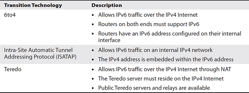
Table 5-4 IPv6 Transition Technologies
Network Infrastructure Services
Network infrastructure is similar to a physical city infrastructure, which includes roads, bridges, and highways that enable the movement of people and goods. In a network environment, some fundamental services are required for large-scale IP addressing, name-to-IP address resolution, and internetwork connectivity.
Default Gateway
The term “default gateway” is an unfortunate choice of words; “gateways” have many meanings, but the term has become standard over the years (“default router” would have made much more sense). The default gateway is a router on your LAN through which you send traffic leaving the LAN. Without it, you are limited to communication with hosts on your local network. Each device that must communicate with devices on other networks must be configured with at least one default gateway IP address.

EXAM TIP One thing to be careful of when given network diagram scenario exam questions is ensuring that you configure the IP address for the router interface connected to your network. Routers have at least two interfaces to interconnect networks. A second thing to watch out for is using the correct subnet mask. You must be able to talk to your router (default gateway) on your LAN.
DNS Servers
It’s probably fair to say that nobody remembers the IP addresses for all of the Internet services (including web sites) that they use. Instead, we humans have an easier time remembering names. It’s no problem remembering www.mheducation.com, but try memorizing 52.72.96.223, and doing similarly for hundreds of different sites where the IP address can change periodically.
Domain Name Service (DNS) is a lookup service that can run on a server or some kind of network appliance such as a router. As users, we normally have a name, but we need the corresponding IP address (your computer needs an IP address, not a name), and this is called a forward lookup. Occasionally, you may already know the IP address, but you’re looking for the corresponding name; this is called a reverse lookup.
Devices on a TCP/IP network must be configured with at least one DNS server IP address (and I would strongly recommend at least two). If the DNS server is down or the client can’t connect to it for some reason, it’s fair to say that everything grinds to a halt.
Using the Windows ipconfig /all command will reveal which DNS servers your network interfaces are configured to use, as shown in the next illustration. On a Linux host, you can open /etc/resolv.conf and add DNS server IP addresses to the file. You can use the nslookup command in both Windows and Linux to test connectivity to DNS servers.

DNS Hierarchy
DNS is a hierarchical naming structure. Top-level domains include suffixes such as .com, .edu, .net, and others. Second-level domains are those such as mheducation, google, and so on. When you add the host name (normally www for Internet web sites), you get a fully qualified domain name (FQDN) such as www.mheducation.com.
The domain suffix can be configured when you configure TCP/IP settings on a device. So if you are configuring IP on a server named server1, you might configure a domain suffix of widgets.com, which results in a FQDN of server1.widgets.com.
Prior to DNS servers becoming common, each TCP/IP device used a local text file called hosts to resolve names to IP addresses. You can imagine how difficult that would be to manage on a large scale.
WINS Servers
The Windows Internet Name Service (WINS) isn’t used often anymore. It is an old Microsoft standard for resolving NetBIOS computer names (such as computer1) to an IP address. It’s a flat structure; there’s no hierarchy as there is in DNS. Prior to WINS servers becoming common, each Microsoft system used a local text file called lmhosts to resolve NetBIOS computer names to IP addresses.
DHCP
Now that you know about configuring TCP/IP settings manually, let’s dive into how this gets done on a larger scale. DHCP, much like DNS, is a standard network service that runs on a server or some network device such as a router (including Wi-Fi routers). To cut to the chase, DHCP is nothing more than TCP/IP settings configured centrally and delivered to clients over the network. But wait! How can that work if a client doesn’t have an IP address in the first place? Read on.
Devices that attempt to acquire TCP/IP settings using DHCP execute a four-packet exchange as follows:
1. DHCP Discover
• The client sends a network broadcast seeking a DHCP server.
• If this fails, the client assigns itself an automatic private IP address (APIPA) that has a prefix of 169.254. This enables communication only on the LAN with other devices in the 169.254 range.
2. DHCP Offer
• Each DHCP server (if more than one) responds via broadcast, if the client does not already have an IP address from a previous DHCP session, with an IP address lease offer. If a client is simply renewing an existing IP address lease, a unicast transmission is sent to the client.
• The DHCP client works with the first offer it receives.
3. DHCP Request
• The client broadcasts its acceptance of the offer, which is received by the DHCP server.
4. DHCP Acknowledgment
• The DHCP server sends an ACK packet to the client along with any additional configured TCP/IP settings. This transmission could be sent via a broadcast if the client doesn’t already have an IP address, or it could be sent via unicast if the client is renewing an existing DHCP lease.
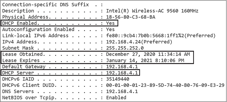
DHCP clients will attempt to renew their leases before they expire. The time interval differs between different versions of operating systems, but generally it’s at 50 percent of the lease. You can use the ipconfig /all Windows command to view DHCP server and lease information, as shown in the next illustration. If you’re a Linux person, you can use the cat command to view the contents of the DHCP lease file, which normally resides at /var/lib/dhcp.
TCP and UDP
TCP is one type of transport available in the TCP/IP suite; User Datagram Protocol (UDP) is the other. Software developers determine whether TCP or UDP will be used. In some rare cases, this may even be a configuration option within a network service or application.
TCP
You’ll come across plenty of literature that states that TCP is a “connection-oriented, reliable protocol.” Great. What exactly does that mean?
It means that a session is established between two communicating devices before transmitting data for the purposes of negotiating session parameters. This is done with the TCP three-way handshake. Let’s detail this packet exchange:
1. SYN Initial sequence number (ISN) is sent by the initiator and is used to track data sent and received.
2. SYN ACK Sent back from the target, this is an acknowledgment of receipt of the initiator’s ISN and also includes the target’s ISN.
3. ACK Sent by the initiator, this acknowledges receipt of the target’s ISN.
4. Data can now be transmitted between the parties and is acknowledged by the opposite end of the connection; otherwise, the packet is retransmitted if the sender doesn’t get an ACK from the recipient after a time interval.
Port Numbers
Network services running on a TCP/IP device need some kind of unique identifier. Let’s say your server has a single IP address of 200.200.1.1 and you’re running a web site and an SMTP mail server. How can you uniquely identify the web server versus the mail server on the same IP address? Easy! Via the port address. It’s similar conceptually to a separate channel of communication. Web servers normally listen on TCP port 80 and SMTP mail servers normally listen on TCP port 25, although administrators can set the listening ports for most services.
Port addresses are also referred to as Layer 4 addresses, whether TCP or UDP. Despite this, protocols such as HTTP, DNS, and SMTP, to name just a few, are Layer 7 protocols. Remember that higher layers in the OSI model rely on some or all lower layers, depending on the specific protocol.
Port numbers are software addresses that uniquely identify network services, and the valid port range falls within 1 to 65,535, where the first 1024 are reserved for well-known services, such as those listed in Table 5-5.
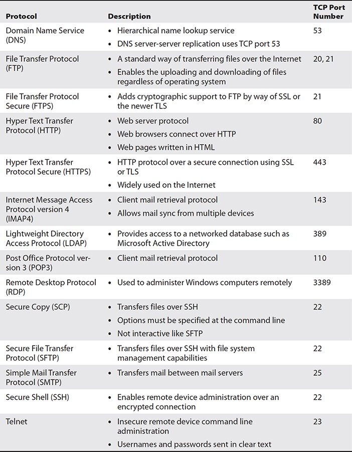
Table 5-5 Common TCP-based Network Services
Use the netstat command in Windows operating systems to see which port you are connected to for a given network service, as well as the local client port used. Client ports and channels are used for network services to transmit data back to clients, and the values are always above 1024. For a more detailed packet analysis, you can capture network traffic using tools such as Wireshark, as shown in Figure 5-11.

Figure 5-11 A Wireshark packet capture showing the fields within a TCP header
UDP
UDP is much simpler than TCP. Because it is neither connection-oriented nor reliable, there is much less overhead at the cost of reliability. You can see this in Figure 5-12. UDP is often used for data transmissions where timing is crucial such as with VoIP, streaming applications, multi user gaming, and DNS queries, to name just a few uses.
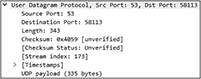
Figure 5-12 A Wireshark DNS packet capture showing UDP header fields
UDP does not use a three-way handshake; there are no sequence numbers and there are no acknowledgments for each packet transmitted. It basically sends out packets and then immediately forgets about it. Like TCP, UDP-based network services are also uniquely identified with a port number. Table 5-6 shows some common UDP-based services.

Table 5-6 Common UDP-based Network Services
Hands-on Exercises
Exercise 5-1: Manually Configure IPv6 on Windows Server
1. Make sure your Srv2019-1 virtual machine is running in VMware Workstation and that you are logged on using the Domain Administrator account (FakedomainAdministrator) with a password of Pa$$w0rd172hfX.
2. From the Windows Start menu, open the Control Panel, click Network and Internet, and then click Network And Sharing Center.
3. On the left, click Change Adapter Settings.
4. Right-click the Internal network adapter and choose Properties.
5. In the Properties window, select Internet Protocol Version 6 (TCP/IPv6), and then click Properties to open the TCP/IPv6 Properties window, shown next.
6. Choose Use The Following IPv6 Address.
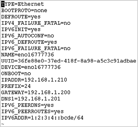
7. In the IPv6 Address field, enter 1:2:3:4::abcd.
8. In the Subnet Prefix Length field, enter 64.
9. Ensure that the Preferred DNS Server is set to ::1. Click OK and then Close.

10. From the Windows Start menu, enter cmd and press ENTER.
11. Type ipconfig and press ENTER. Notice that the Internal network adapter has both an IPv6 address and a link-local IPv6 address.
12. Type ping 1:2:3:4::abcd and press ENTER. You should see four replies. Leave the virtual machine running.
Exercise 5-2: Manually Configure IPv4 and IPv6 on Ubuntu Linux
1. Make sure your Ubuntu-1 virtual machine is running in VMware Workstation and that you are logged in as user uone with a password of Pa$$w0rd172hfX. Ensure that the Srv2019-1 virtual machine is also running.
2. On your Ubuntu-1 computer, enter ip a to list network interfaces. One of the interface listings will already have an IPv4 address in the 192.168 range through DHCP. Take note of this interface name, such as ens33.
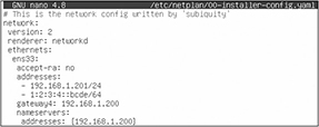
3. Type sudo nano /etc/netplan/, and then press TAB to complete the network configuration filename in the /etc/netplan/ directory. The filename will look something like this: 00-installer-config.yaml.
Make sure the file contents look like the following, replacing ens33 with whatever your network interface name is from step 3:

4. Press CTRL-X, press Y, and press ENTER to save the configuration file
5. Type sudo netplan try and press ENTER to test the syntax. No errors will be reported if the syntax in the file is correct, in which case press ENTER to apply the new network configuration.
6. Type ip a and press ENTER. For your network interface, you will see that the 192.168.1.201 and 1:2:3:4::bcde IP addresses are listed.
7. Switch to the Srv2019-1 virtual machine and open a command prompt. Type ping 192.168.1.201 and press ENTER. This is the IPv4 address of the Linux server. You should see four replies.
8. On the Srv2019-1 virtual machine, type ping -6 1:2:3:4::bcde. This is the IPv6 address of the Linux server. You should see four replies.
Exercise 5-3: Install and Configure NAT on Windows Server
1. Make sure your Srv2019-1 virtual machine is running in VMware Workstation and that you are logged on using the Administrator account with a password of Pa$$w0rd172hfX.
2. Start Windows PowerShell from the Start menu.
3. Enter the following:
install-windowsfeature routing -includemanagementtools
4. After the Routing and Remote Access server role is installed, leave PowerShell running, and from the Windows Start menu, type Rout. When the Routing And Remote Access option appears, click it.
5. Right-click Srv2019-1 in the left panel and choose Configure And Enable Routing And Remote Access. Click Next.
6. Choose Network Address Translation (NAT) and click Next.
7. Click ExternalNAT for the public interface. Click Next, and then Finish. If you receive a message related to firewall ports, click OK.
8. To allow ICMP ping packets to Srv2019-1, from PowerShell, enter the following:
![]()
9. On the Ubuntu-1 virtual machine, in a terminal window, type ping www.mheducation.com. The name will be resolved to an IP address and you will see replies, because NAT (technically PAT!) on Srv2019-1 is allowing access to the Internet; all outbound traffic from internal hosts will assume the address of 200.1.1.1.
NOTE Network devices can use NAT only if the internal IP address of the NAT router is set as their default gateway.
Exercise 5-4: Use Wireshark to Capture and Analyze HTTP Traffic
This exercise can be completed from any Windows computer that has access to the Internet, where the computer allows downloading and installing software from the Internet.
1. Using the web browser on your computer (and not in the lab virtual machines), go to www.wireshark.org. Download and install the appropriate Windows Installer and then accept all installation defaults. Leave the web browser open.
2. From the Start menu, launch Wireshark.
3. Double-click a network interface your computer uses for Internet connectivity (the name could be just about anything), where there is a squiggly line (this means network activity). Don’t click network interfaces for VMware; you want to capture network traffic on your real computer. Wireshark will then capture network packets on the selected network interface.
4. Switch over to your web browser and connect to www.mheducation.com.
5. Switch back to Wireshark, and choose Capture | Stop. Notice all of the captured network packets.
6. In the address bar (it should currently say Apply A Display Filter), type http and press ENTER. Now only HTTP network traffic is shown.
7. Choose Edit | Find Packet. On the newly displayed search line, select the Display Filter drop-down and click String. To the far left on the same line, click Packet List and choose Packet Details. In the field to the right, type mheducation. Click the Find button on the far right. The first HTTP packet containing mheducation is selected.
8. In the middle of the screen, you will see packet headers. Select the Transmission Control Protocol header. Notice the source and destination port values. If the packet is an HTTP transmission to the web site, the destination port will be 80 (443 for HTTPS) and the source port will be a higher value; otherwise, the port numbers will be reversed. These are Layer 4 addresses.
9. In the packet header section, select the Internet Protocol Version 4 header. You may need to scroll down a bit in the middle panel to see the source and destination IP addresses. These are Layer 3 addresses.
10. In the packet header section, select the Ethernet II header. Notice the source and destination MAC addresses. These are Layer 2 addresses.
11. Close Wireshark without saving the capture.
NOTE Do you see how the OSI model layers are reflected in sequence (Layers 2, 3, 4, and so on) when viewing packet headers? This is not a coincidence.
Chapter Review
If it seems to you that server experts must also be network experts, you are correct! Your servers can interact with a large variety of services and network components on a large scale, and you must understand how all the moving parts work together.
The OSI Model
The seven-layer OSI model is used to explain communication hardware and software, and the layers, beginning with Layer 7, are application, presentation, session, transport, network, data link, and physical.
• Higher level software applies to Layer 7, the application layer.
• How data is presented applies to Layer 6, the presentation layer.
• The establishment, maintenance, and termination of sessions apply to Layer 5, the session layer.
• Port numbers apply to Layer 4, the transport layer.
• IP addresses apply to Layer 3, the network layer.
• MAC addresses apply to Layer 2, the data link layer.
• Cables, connectors, and electrical specifications apply to Layer 1, the physical layer.
Cables and Connectors
Groups of cables should be bundled together and routed in cable channels in racks throughout server rooms and data centers. Cable management arms prevent cables from being pulled tight when rack-mounted equipment is pulled out on rails from the rack. Labeled or color-coded cables keep things organized and facilitate troubleshooting.
RJ-11 connectors are used for telephone cables, and RJ-45 connectors are used for twisted pair copper network cables, which transmit electronic signals. CAT5 cabling supports transmissions at 10 or 100 Mbps. CAT5e has more cable pair twists per inch and supports up to 1000 Mbps. CAT6 supports 1 Gbps over 100 meters or 10 Gbps over 55 meters.
Fiber-optic cables transmit light waves, and data can travel greater distances without amplification. Single-mode fiber is used for longer distances than multi-mode fiber. Common connectors include ST, SC, LC, and SFP.
Network Interface Cards
NICs can be integrated on server motherboards or are available as expansion cards. NICs have a unique 48-bit hardware address called a MAC address, and they support enhanced features such as Wake-on-LAN, PXE boot, and NIC teaming. NIC teaming groups multiple network cards together for the purpose of redundancy or greater bandwidth.
IPv4 and IPv6
IPv4 uses a 32-bit IP address space, where each 8 bits is expressed in decimal format and separated by a period. TCP/IP configuration settings can be configured manually on each device or configured centrally using DHCP. The subnet mask determines which portion of the IP address designates the network and which portion designates the host on that network.
Subnetting occurs when host bits are borrowed to address subnetworks beyond the original network. This is done when additional network addresses cannot be acquired. In subnetting, all affected devices use the same new subnet mask.
Port Address Translation (PAT) enables multiple internal IP nodes to access a public network, such as the Internet, using a single public IP address. Network address translation (NAT) exposes internal hosts by mapping public IP addresses on the NAT router to internal private IP addresses.
IPv6 improves upon IPv4 with a larger 128-bit address space, security using IPSec, and more efficient network traffic management. IPv6 addresses are exposed in hexadecimal, where every 16 bits is separated by a full colon.
The default gateway is used when a device is transmitting data to a remote network outside of the LAN, and it must be on the same subnet as the device; the gateway is the IP address of a router. DNS servers provide a lookup service, most often for name-to-IP address resolution. Devices should point to at least one DNS server IP address for name resolution.
IP, TCP, and UDP
In the TCP/IP suite, IP is responsible for routing. TCP provides connection-oriented reliable transmissions, whereas UDP does not and is therefore quicker. Network services listen on a port address for client connections; the port must be unique on a given IP address. The first 1024 ports are reserved for well-known services such as an HTTP web server listening on TCP port 80.
Questions
1. Which of the following is a valid concern regarding ceiling cable channels?
A. Distance
B. EMI
C. Fire suppression
D. Security
2. What is the primary difference between the categories of copper-based network cables?
A. Twists per inch
B. Shielding
C. Type of NIC
D. Distance
3. Which type of connector is commonly used with CAT6 cables?
A. RJ-11
B. SFP
C. TX
D. RJ-45
4. Tamil is a network technician linking two older Ethernet switches together with a straight-through network cable. She later realizes the interswitch connection is not working. What should Tamil do?
A. Replace the straight-through cable with a rollover cable.
B. Replace the straight-through cable with a crossover cable.
C. Replace the straight-through cable with a null modem cable.
D. Replace the straight-through cable with a switch cable.
5. You are planning the cabling for your company’s data center. A network speed of 10 Gbps is preferred. The maximum distance between servers and network switches is approximately 30 meters. Keeping costs to a minimum, what type of network cabling should be used?
A. CAT5
B. CAT6
C. CAT6A
D. CAT7
6. Which type of fiber-optic cable should be used for the network backbone on a university campus?
A. Single-mode
B. Unimode
C. Dual-mode
D. Multi-mode
7. Which spring-loaded fiber-optic cable connector is commonly used with multi-mode fiber cables?
A. SC
B. LC
C. ST
D. LT
8. Which of the following statements best describe MAC addresses? Choose two.
A. They are used to route network packets.
B. Packets being sent to a host on a remote network are addressed to the host’s MAC address.
C. MAC addresses are 48 bits long.
D. Each server NIC has a unique MAC address.
9. A data center uses disk images to deploy new physical servers quickly. Rather than have technicians apply the operating system images locally from disk media, network imaging is desired. Which technology must be configured?
A. Wake-on-LAN
B. NIC teaming
C. Full duplex
D. PXE
10. Server1 has an IP address of 200.1.1.40/27. From Server1, you are attempting to make an SSH connection to Server2, whose IP address is 200.1.1.70/27, but you cannot connect. What might the problem be?
A. /27 is invalid.
B. 200.1.1.0 is a reserved IP range.
C. A default gateway is not properly configured on both servers.
D. UDP port 22 is blocked on Server2.
11. Which of the following is a valid IPv6 link-local address?
A. fe80::883b:ced4:63f3:f297
B. fd75::883b:ced4:63f3
C. fe80::883b:ced4:63f3:fh97
D. fd75::883b:ced4:63g3
12. Widgets, Inc., has offices in London and Paris. The IT team has been directed to deploy IPv6 for test VLANs in both cities in anticipation of the eventual requirement of using IPv6. What should be configured to ensure that servers in each city test VLAN can communicate over the Internet?
A. 6to4
B. ISATAP
C. Teredo
D. NAT
13. A help desk technician is addressing network connectivity issues being experienced by a user, Charlie. Charlie’s station is unable to connect to a customer financial history database server on the same subnet named sect1-423.widgets.local, even though other stations do not have this problem; the error messages states “Unknown Host.” The technician successfully pings the default gateway to verify a valid IP configuration from Charlie’s station. What should the technician do next?
A. Nothing. The server is down.
B. Verify that Charlie’s station has a default gateway configured.
C. Verify that Charlie has authenticated to the server first.
D. Verify that Charlie’s station is properly configured with at least one DNS server.
14. Your smartphone receives an alert stating that ServerHFX-234 is not responding. You connect to the server using hardware remote control and issue the ipconfig command. You then notice the server IP address is 169.254.46.63. Why is the server having communication problems?
A. The machine was unable to reach a DHCP server.
B. The machine must be configured with a private IPv4 address.
C. The machine is not configured with a DNS server IP address.
D. The machine is not configured with a valid subnet mask.
15. A colleague, Malia, discusses the newly installed Layer 3 switches in the wiring closet. What benefit does a Layer 3 switch offer beyond a Layer 2 switch?
A. Bridging
B. Switching
C. Routing
D. VLANs
16. Which of the following are valid methods of configuring VLAN membership? Choose two.
A. Username
B. IP address
C. Switch port
D. PKI certificate
17. What type of address applies to Layer 2 switches?
A. IP
B. Port
C. LUN
D. MAC
18. What type of address applies to Layer 3 switches?
A. IP
B. Port
C. LUN
D. MAC
19. Which software communication method is not used with IPv6?
A. Broadcast
B. Unicast
C. Multicast
D. Anycast
20. A new HTTP intranet web server is installed. Your boss asks you to configure the firewall appliance to enable people to browse to the new site. Which port should be allowed through the firewall appliance?
A. 25
B. 110
C. 80
D. 443
Questions and Answers
1. Which of the following is a valid concern regarding ceiling cable channels?
A. Distance
B. EMI
C. Fire suppression
D. Security
C. Ceiling cable channels must be oriented carefully to avoid reducing the effectiveness of fire suppression systems. A, B, and D are incorrect. Although distance is a concern, because cables have a maximum effective distance, this is much less relevant than fire suppression. EMI can be a concern if ceilings have fluorescent lighting and cables are unshielded, neither of which is mentioned. Ceiling cable channels have no bearing on security.
2. What is the primary difference between the categories of copper-based network cables?
A. Twists per inch
B. Shielding
C. Type of NIC
D. Distance
A. More twists per inch for copper wire pairs means less interference from adjacent wires. This allows for transmissions at higher frequencies, which results in greater bandwidth. B, C, and D are incorrect. Although some categories of cables differ in their shielding, this is not as prevalent a difference as twists per inch. The type of NIC and the distance are not distinguishing differences between different copper cable categories.
3. Which type of connector is commonly used with CAT6 cables?
A. RJ-11
B. SFP
C. TX
D. RJ-45
D. RJ-45 connectors are common with CAT6 cables. A, B, and C are incorrect. RJ-11 connectors are used with telephone cables. SFP is a hot-pluggable network transceiver used most often to interconnect fiber cables. TX is not a valid network cable connector type.
4. Tamil is a network technician linking two older Ethernet switches together with a straight-through network cable. She later realizes the interswitch connection is not working. What should Tamil do?
A. Replace the straight-through cable with a rollover cable.
B. Replace the straight-through cable with a crossover cable.
C. Replace the straight-through cable with a null modem cable.
D. Replace the straight-through cable with a switch cable.
B. Crossover cables reverse the transmit and receive wires at either end, which is sometimes required for older network switches. A, C, and D are incorrect. Rollover cables are used to connect administrative stations to the console port on network equipment such as routers. Null modem cables are used to link modem devices directly together. There is no such thing as a switch cable.
5. You are planning the cabling for your company’s data center. A network speed of 10 Gbps is preferred. The maximum distance between servers and network switches is approximately 30 meters. Keeping costs to a minimum, what type of network cabling should be used?
A. CAT5
B. CAT6
C. CAT6A
D. CAT7
B. CAT6 cabling supports 10 Gbps over distances up to 55 meters. A, C, and D are incorrect. CAT5 supports up to 1 Gbps. CAT6A and CAT7 would work but are more costly than CAT6.
6. Which type of fiber-optic cable should be used for the network backbone on a university campus?
A. Single-mode
B. Unimode
C. Dual-mode
D. Multi-mode
D. Multi-mode fiber should be used over shorter distances, such as on a university campus. A, B, and C are incorrect. Single-mode fiber is often used over longer distances and is more expensive than multi-mode. Unimode and dual-mode fiber are not common terms.
7. Which spring-loaded fiber-optic cable connector is commonly used with multi-mode fiber cables?
A. SC
B. LC
C. ST
D. LT
C. ST connectors are commonly used with multi-mode fiber-optic cables. A, B, and D are incorrect. SC connectors are square shaped and not spring-loaded. LC connectors, like SC, are square snap-in connectors that are commonly used with single-mode fiber-optic cables. LT is not a valid type of connector.
8. Which of the following statements best describe MAC addresses? Choose two.
A. They are used to route network packets.
B. Packets being sent to a host on a remote network are addressed to the host’s MAC address.
C. MAC addresses are 48 bits long.
D. Each server NIC has a unique MAC address.
C, D. MAC addresses are 48 bits long and expressed in hexadecimal format. Each server NIC will have its own unique MAC address. A and B are incorrect. IP addresses are used to route packets, not MAC addresses. Transmitting nodes do not know the MAC address of a target node on a remote network.
9. A data center uses disk images to deploy new physical servers quickly. Rather than have technicians apply the operating system images locally from disk media, network imaging is desired. Which technology must be configured?
A. Wake-on-LAN
B. NIC teaming
C. Full duplex
D. PXE
D. PXE booting makes it possible to boot from a NIC to retrieve a small operating system from a boot server that runs locally in server RAM. This is commonly used for imaging. A, B, and C are incorrect. Wake-on-LAN is used to wake up powered-down systems and should be used for desktops and not servers. NIC teaming is used to group together server NICs to increase bandwidth or redundancy. Full-duplex communication enables traffic to be sent and received simultaneously over the network cable.
10. Server1 has an IP address of 200.1.1.40/27. From Server1, you are attempting to make an SSH connection to Server2, whose IP address is 200.1.1.70/27, but you cannot connect. What might the problem be?
A. /27 is invalid.
B. 200.1.1.0 is a reserved IP range.
C. A default gateway is not properly configured on both servers.
D. UDP port 22 is blocked on Server2.
C. A default gateway is not properly configured on both servers. A, B, and D are incorrect. The /27 is a valid subnet mask, 200.1.1.0 is not a reserved IP range, and SSH uses TCP (not UDP) port 22.
11. Which of the following is a valid IPv6 link-local address?
A. fe80::883b:ced4:63f3:f297
B. fd75::883b:ced4:63f3
C. fe80::883b:ced4:63f3:fh97
D. fd75::883b:ced4:63g3
A. fe80::883b:ced4:63f3:f297 is a valid IPv6 link-local address. Link-local addresses are self-assigned by IPv6 nodes and enable LAN communications. This type of address is always present on IPv6 nodes. B, C, and D are incorrect. fd75::883b:ced4:63f3 is not a link-local address; the prefix must be fe80. In addition, fe80::883b:ced4:63f3:fh97 and fd75::883b:ced4:63g3 are invalid; hexadecimal uses only numbers 0–9 and letters A–F.
12. Widgets, Inc., has offices in London and Paris. The IT team has been directed to deploy IPv6 for test VLANs in both cities in anticipation of the eventual requirement of using IPv6. What should be configured to ensure that servers in each city test VLAN can communicate over the Internet?
A. 6to4
B. ISATAP
C. Teredo
D. NAT
A. 6to4 enables IPv6 networks to communicate over the IPv4 Internet; routers in both locations must support IPv6 on their internal interfaces. B, C, and D are incorrect. ISATAP is used on an IPv4 intranet, not the Internet. The Teredo standard enables IPv6 communication over the IPv4 Internet for IPv6 nodes behind NAT routers.
13. A help desk technician is addressing network connectivity issues being experienced by a user, Charlie. Charlie’s station is unable to connect to a customer financial history database server on the same subnet named sect1-423.widgets.local, even though other stations do not have this problem; the error messages states “Unknown Host.” The technician successfully pings the default gateway to verify a valid IP configuration from Charlie’s station. What should the technician do next?
A. Nothing. The server is down.
B. Verify that Charlie’s station has a default gateway configured.
C. Verify that Charlie has authenticated to the server first.
D. Verify that Charlie’s station is properly configured with at least one DNS server.
D. DNS enables connections to hosts by name instead of IP addresses. A, B, and C are incorrect. We know the server is not down because other stations can connect. The default gateway is not used for communication on the local subnet. Authentication is not the problem, because we know the error is that the server name is not even a known host.
14. Your smartphone receives an alert stating that ServerHFX-234 is not responding. You connect to the server using hardware remote control and issue the ipconfig command. You then notice the server IP address is 169.254.46.63. Why is the server having communication problems?
A. The machine was unable to reach a DHCP server.
B. The machine must be configured with a private IPv4 address.
C. The machine is not configured with a DNS server IP address.
D. The machine is not configured with a valid subnet mask.
A. Systems will assign themselves an APIPA address beginning with 169.254 when a DHCP server cannot be contacted. B, C, and D are incorrect. The symptom does not indicate in any way that the server needs a private IPv4 address, DNS server, or subnet mask configuration.
15. A colleague, Malia, discusses the newly installed Layer 3 switches in the wiring closet. What benefit does a Layer 3 switch offer beyond a Layer 2 switch?
A. Bridging
B. Switching
C. Routing
D. VLANs
C. Layer 3 switches can use IP routing to transmit packets to destination networks instead of relying solely on MAC addresses and switch ports. A, B, and D are incorrect. Bridging is a Layer 2 mechanism for network segmentation that is based on MAC addresses. Although switching can apply to Layers 2 and 3, it is not solely related to Layer 3. Virtual local area networks (VLANs) are also available with Layer 2 switches, such as port-based VLANs, which group devices together based on the switch ports they are plugged into.
16. Which of the following are valid methods of configuring VLAN membership? Choose two.
A. Username
B. IP address
C. Switch port
D. PKI certificate
B, C. Switch administrators can configure VLAN membership by IP address and by switch port. A and D are incorrect. Usernames and PKI certificates are not used to configure VLAN membership.
17. What type of address applies to Layer 2 switches?
A. IP
B. Port
C. LUN
D. MAC
D. MAC addresses are Layer 2 addresses. The MAC address is the hardware address of a network interface. A, B, and C are incorrect. IP addresses are Layer 3 addresses, ports are Layer 4 addresses, and a LUN is a unique value assigned to network storage.
18. What type of address applies to Layer 3 switches?
A. IP
B. Port
C. LUN
D. MAC
A. IP addresses are Layer 3 addresses. B, C, and D are incorrect. Port addresses apply to Layer 4, LUNs are unique values assigned to network storage, and MAC addresses are Layer 2 hardware addresses.
19. Which software communication method is not used with IPv6?
A. Broadcast
B. Unicast
C. Multicast
D. Anycast
A. IPv6 does not use software broadcasts. B, C, and D are incorrect. IPv6 unicasts are one-to-one transmissions, multicasts are one-to-many, and anycast traffic is sent to the nearest device interface configured with the anycast address.
20. A new HTTP intranet web server is installed. Your boss asks you to configure the firewall appliance to enable people to browse to the new site. Which port should be allowed through the firewall appliance?
A. 25
B. 110
C. 80
D. 443
C. HTTP web servers normally listen for client connections on TCP port 80. A, B, and D are incorrect. SMTP uses port 25, POP3 uses 110, and HTTPS uses 443.