Chapter 10
Infrastructure Security
Lab Exercises
10.01 Port Security on Switches
10.02 Standard ACLs on Routers
10.03 Extended ACLs on Routers
Lab Analysis
Key Term Quiz
You created an infrastructure in Chapter 9, but it’s not yet ready to open for business. Certain security precautions need to be put in place. Just as locks and a security alarm system are placed on a building before it opens for business, your infrastructure of Layer 2 switches and Layer 3 routers needs to be protected.
In this chapter you’ll configure important infrastructure security mechanisms, including port security on switches and access control lists (ACLs) on routers.
![]() 60 MINUTES
60 MINUTES
Lab Exercise 10.01: Port Security on Switches
As discussed in Chapter 9, Ethernet switches learn where hosts are by analyzing the source MAC address field in Ethernet frames as the frames enter switch ports and by keeping mappings of MAC addresses to ports in a table in RAM called the content addressable memory (CAM) table, source address table (SAT), or MAC address table.
The switch can keep a specific number of MAC addresses in this table. The size of the table and the number of entries each vary by switch. What would happen if an attacker connects a device to a port and runs a tool or script that sends thousands of Ethernet frames into the port with different, randomly generated MAC addresses? In this case, the switch would happily enter each MAC address into the CAM table, associating each MAC address with the same physical port of the attacker. Eventually, the CAM table will run out of space. At this point, the switch can’t learn any new MAC addresses and will simply start flooding all traffic from all hosts out of all ports on the switch, except the originating port.
This CAM overflow attack, also known as a MAC flooding attack, essentially turns a switch into an old, obsolete networking device called a hub, which always flooded traffic out of all ports except the port on which the message originated. The switch and its CAM table put hubs out of business.
With this attack, the attacker is now able to sniff every single frame sent into the switch. The attacker could be an insider, physically on the premises, or an outsider with remote access to one of the organization’s machines. Confidentiality is at great risk. macof, part of the dsniff suite of tools, can generate hundreds of thousands of random MAC addresses and flood them into a switch. From a cybersecurity perspective, this tests your switch’s resistance to such an attack. To mitigate this attack, you can use a switch feature called port security.
First, you need to identify allowed MAC addresses so they can get access to the port. This can be done either statically or dynamically, as frames enter a port. The next step involves specifying the maximum number of MAC addresses that will have access to the port. By default, only one MAC address has access. In a switched environment, the main reason that more than one MAC address will be heard from on a single port is that the port is connected to a neighboring port. For example, all traffic coming into SwitchA, from hosts in SwitchB, will be heard through the port on SwitchA that connects to SwitchB. A second example of when multiple MAC addresses can be learned on a single port involves the use of virtual machines (VMs), where the VM sends frames with a source MAC address of its virtual NIC, which will be different from the MAC address of the physical NIC of the host. A third example of multiple MAC addresses being learned on a single port is when a VoIP (Voice over IP) phone is connected to a switch just with a PC, and that switch then connects upstream to another switch.
A violation occurs if a new MAC address is heard on a port after the maximum number of MAC addresses have been learned. On ports that are statically configured for certain MAC addresses, an unknown MAC address heard on that port would trigger a violation as well. When a violation occurs, the switch will enter one of three states and take appropriate action.
First, the shutdown mode is when the port is immediately shut down. No frames can enter or exit, and an SNMP (Simple Network Management Protocol) trap notification is sent. The network engineer must re-enable the port manually, although the switch can be configured to have ports shut down because of errors and come back up again after a certain period of time has elapsed.
Second, the restrict mode is when the port doesn’t shut down, but all frames from violating MAC addresses are discarded. The switch logs the number of violating frames and can send an SNMP trap, as well as a syslog message, if configured to do so.
Third, the protect mode is when the port doesn’t shut down, but all frames from violating MAC addresses are discarded. So far, this state is exactly the same as restrict. The only difference is that in this state, no violations are logged. I’ve never heard of a valid use case—or even a contrived one—that works for this state. No sane administrator would want to stick their head in the sand like an ostrich and ignore violations!
As if a CAM overflow attack wasn’t enough motivation for implementing port security, there are still other compelling reasons. First, imagine an organization dealing with sensitive, personally identifiable information (PII), like a healthcare organization or even the government. You would imagine that every device on that network would be tightly controlled and tracked, while personal devices would be forbidden. After a MAC address of a company device is learned on the port (which will happen instantly when it is set up for the first time), users would not be able to unplug it and plug in their own device. If someone tried that, the port would be shut down and an administrator would need to manually bring it up again.
Furthermore, port security also prevents users from plugging in unauthorized switches into ports, to allow multiple devices of theirs to connect to the network. In this case, the switch could just restrict and not completely shut down, to allow the user to keep working, while unauthorized devices will not be able to send traffic into the switch. In this case, too, the administrator will get alerts.
Finally, let’s say there’s a VoIP phone or a kiosk machine available for employees, or even visitors, to use. Port security will prevent someone from unplugging one of those devices and plugging in a personal device when the switch only allows the initial MAC address learned on the port to send frames into the port.
Learning Objectives
In this lab exercise, you’ll restrict traffic going into Layer 2 switches. At the end of this lab exercise, you’ll be able to
• Configure port security
• Test port security
• Analyze port security results
Lab Materials and Setup
The materials you need for this lab are
• The Principles of Computer Security: CompTIA Security+ and Beyond textbook
• A web browser with an Internet connection
• Completed lab exercises in Cisco Packet Tracer from the previous chapter
• One or more Cisco Ethernet switches with at least two PCs (optional, as an alternative to Packet Tracer)
Let’s Do This!
This lab exercise continues with the topology established in the previous chapter. If you haven’t completed that chapter, you must go back and complete it before attempting the lab exercises in this chapter. Please refer to Figure 9-3 from Chapter 9 for the topology.
Furthermore, some of the instructions assume you learned how to move around the different modes of the routers and switches, as well as navigate the devices in the Packet Tracer topology from the previous chapter.
![]() Note
Note
Press ENTER after each command.
![]() 1b
1b
Step 1 Enable and configure port security on Switch0.
a. On Switch0, from user EXEC mode, type enable to go to enable mode (privileged EXEC mode). Next, type configure terminal to go to global configuration mode. Finally, type configure interface f0/1 to go to interface configuration mode for interface FastEthernet0/1. PC0 (10.1.0.100) is connected to this interface.
b. Type the following commands:
switchport mode access
switchport port-security
switchport port-security mac-address sticky
The first command explicitly declares this port as an access port, which means that a PC is connected to it rather than a switch. When a port on a switch is connected to another switch, those ports are considered trunk ports. Without explicitly declaring the mode, the switch determines what a port is connected to dynamically. However, port security requires an interface type to be explicitly declared prior to port security being enabled.
The second command enables port security on just the current port. Port security will dynamically learn MAC addresses and store them in the CAM table and the running configuration file. However, if the switch is rebooted, those dynamically learned MAC addresses go away.
The third command instructs the switch to keep learned addresses even after a reboot. Therefore, the first MAC address coming into the switch will be that of the PC connected to it, as set up by the administrator. That address will already be the learned MAC address (and by default only one MAC address can be heard on the port, as explained next) by the time a user brings an unauthorized device to work.
c. If you wanted to tweak a couple of the defaults, the following commands would be helpful. However, do not execute them at this time.
switchport port-security maximum 2
switchport port-security violation restrict
The first command changes the maximum number of MAC addresses allowed on the port from the default of 1 to the specified number of 2. As mentioned earlier, this could be for a VM or VoIP phone. The second command changes the default mode of shutdown to restrict. As mentioned earlier, this could be so an employee who plugs in a switch could keep working, while the traffic from the unauthorized devices are dropped and alerts are sent to an administrator. There is no reason to ever set this mode to protect, though, as there isn’t even a contrived example that would be a valid justification to keep the port up and not log any dropped traffic.
Also, as an alternative to the sticky command, the following command can be used to preload MAC addresses expected to be heard on the port:
switchport port-security mac-address [actual MAC address]
![]() 2a–2d
2a–2d
Step 2 Send traffic through the switch and observe what the switch learned regarding port security.
a. From PC0 (10.1.0.100), ping PC3 (10.4.0.3). You should get four ICMP Echo replies.
b. From Switch0, type the following commands from enable mode:
show port-security
show port-security interface FastEthernet0/1
show running-config
The first command shows port security summary information. The second command shows port security information for interface FastEthernet0/1. The third command shows the running configuration. Find the related port security commands, configuration information, as well as the sticky learned MAC address of PC0 (10.1.0.100) in the outputs of these commands.
c. Type the following commands from enable mode:
copy running-config startup-config
reload
The first copies the running configuration file from dynamic RAM to NVRAM, where it’s known as the startup configuration file and is read and loaded the next time the device boots up or is reloaded. The second command reloads (reboots) the switch.
d. Again, type the following commands from enable mode. You’ll notice that the port security information, specifically the sticky learned MAC address of PC0 (10.1.0.100), survived the reload.
show port-security
show port-security interface FastEthernet0/1
show running-config
![]() 3a–3c
3a–3c
Step 3 Change PC0’s MAC address and then send traffic from PC0 into the switch. This will trigger port security into action.
a. On PC0 (10.1.0.100), click the Config tab. Select FastEthernet0 on the left and replace the value in the MAC Address field on the right with BAD1.BAD2.BAD3.
b. From PC0 (10.1.0.100), ping PC3 (10.4.0.3) again. Instead of the replies like last time, you’ll see “Request timed out.” messages in the command prompt. You’ll also notice that the green arrows, representing the interfaces on PC0 (10.1.0.100) and interface FastEthernet0/1 of Switch0, have changed from green to red.
c. Type the following commands from enable mode of Switch0 yet again. You’ll notice from these commands that the port status is Secure-shutdown, the unauthorized MAC address (BAD1.BAD2.BAD3) is logged, and the line protocol is down (err-disabled) for interface FastEthernet0/1.
show port-security
show port-security interface FastEthernet0/1
show interface FastEthernet0/1
![]() 4a–4c
4a–4c
Step 4 Allow the port that was shut down by port security to come back up and return to the way it was before it entered the err-disabled state.
a. To recover from this state, an administrator must manually disable (yes, disable) the interface with the shutdown interface command and then enable the interface with the no shutdown command. So, now is a good time to execute the following commands in interface configuration mode for interface FastEthernet0/1:
shutdown
no shutdown
b. Another look at the output from these commands shows that the port status has now returned to Secure-up, the last MAC address heard on the interface is still the unauthorized one, and the line protocol is up (connected) for interface FastEthernet0/1:
show port-security
show port-security interface FastEthernet0/1
show interface FastEthernet0/1
c. Now to get things fully back to normal. If you look in the running-config, you’ll notice the following line (your MAC address might vary):
switchport port-security mac-address sticky 0060.2FE3.20C0
That was the MAC address of PC0 before you changed it. Restore that MAC address back to PC0 now.
If you wanted to remove the sticky address from the configuration (which isn’t necessary now and shouldn’t be done), you would use this the command:
clear port-security sticky
From PC0 (10.1.0.100), send a ping to PC3 (10.4.0.3). Now this will work once again. For completeness purposes, from enable mode, copy the running-config to the startup-config:
copy running-config startup-config
![]() 60 MINUTES
60 MINUTES
Lab Exercise 10.02: Standard ACLs on Routers
Let’s say you have some hosts on a particular subnet that should have access to other subnets in your autonomous system, with the exception of a specific subnet where servers are storing sensitive data. Maybe one specific host from a subnet should be allowed to access a specific service on a certain machine, but not others. There could even be government privacy regulations that require you to prevent or allow packets from reaching certain servers.
Enter the stateless packet filter, which, through a set of rules, either lets packets in or denies their entrance to a network as well as lets packets out or denies their exit from a network.
The best example of a stateless packet filter is an IP ACL, which will permit or deny packets from entering inbound or exiting outbound the network, based on criteria such as source IP address, destination IP address, protocol, and port (a logical port, representing a connection endpoint). Later we’ll see the terms inbound and outbound are flipped with ACLs, when used in relation to the router and not the network.
IP ACLs filter by Layers 3 and 4 information of the OSI (Open Systems Interconnection) model, so they don’t use MAC addresses as a criteria since MAC addresses are found in Layer 2 frames. If you did want to filter at Layer 2, you would use a MAC ACL. Other types of ACLs include a VLAN ACL and a port ACL. The next two lab exercises will focus on an IP ACL using Cisco routers.
IP ACLs can be configured on a router or a standalone firewall like Cisco’s Adaptive Security Appliance (ASA). An ACL has multiple lines of instructions that are processed in a sequential order. In fact, order does matter, unlike a shopping list. When my wife gives me a shopping list, the order in which I get the items doesn’t matter. I could get the milk, bread, eggs, cereal, ice cream, taco kit, and pancake mix in any order I want. However, the order of instructions in an ACL is crucial. Ordering the instructions incorrectly could actually do the opposite of what you intended to do. Certain packets that should be denied will be permitted. Certain packets that should be permitted will be denied. In the world of cybersecurity, that sets you up to be breached or to be the victim of a possible denial-of-service (DoS) attack.
An ACL is a list of multiple instructions or statements. Some instructions permit traffic, while others deny traffic. As soon as a packet is matched to a statement based on source IP address, destination IP address, protocol, or port, the packet is either permitted or denied, regardless of what comes later in the ACL.
ACLs are processed from the first line, and then all the subsequent lines sequentially down, until a match is found. If a general statement in one of the first few lines of an ACL denies a specific packet, it’s denied, even if there’s a more specific statement later in the ACL that would permit the packet. The packet will never reach the later line because as soon as a match is made, the packet is dealt with at the earlier line. There’s no branching or looping. There’s no comparing general statements to more specific ones.
If no statements in the configured ACL match a packet, the packet will meet an explicit deny any statement at the end of every ACL that just discards the packet. After all, if we have no instruction that deals with the packet in our configured statements, from a cybersecurity perspective, it makes sense to just drop the packet instead of letting it into or out of a network.
ACLs come in two types: standard and extended. Standard ACLs can only permit or deny by the source IP address in a packet header. Extended ACLs permit or deny by source IP address as well, but they can also use two or three other criteria: destination IP address, protocol, and port. Interestingly enough, if you’re using an extended ACL, you must use the source IP address, the destination IP address, and the protocol. The only optional parameter is the port.
Source IP address or destination IP address can actually mean three different things. First, it can be an actual IPv4 address assigned to a client or server system, for example, 129.21.1.40, which is the IP address of the Rochester Institute of Technology (RIT) web server. Second, it could be a classful address that all subnets inside of an autonomous system start off with. For example, RIT was one of the privileged organizations to receive a Class B address block of 129.21.0.0/16, back in the days of classful addressing. There are many internal networks at RIT, and they all start with the same first two octets of 129.21. Finally, it can be a specific subnet. As just mentioned, 129.21.0.0/16 represents all RIT networks, but an ACL can deal with just a specific subnet using that subnet’s network ID, for example, 129.21.1.0/24.
Now you might be wondering, if an extended ACL can do what a standard ACL can do, and then some, what’s the purpose of having a standard ACL? If you wanted to permit or deny based on an IP address—whether it’s an actual host address, a classful address, or a subnet and network ID—the router implementing the stateless packet filter just needs to check one field in the IP header: the source IP address. This is basically whitelisting a legitimate device or blacklisting a nefarious device. Once you start to add other criteria to check, like destination IP address, protocol, and port, the latency increases, as each packet will be put up against multiple lines of instructions and multiple tests at each line. It will take much more time for packets to go inbound to a router and outbound from a router. Now three or four fields need to be checked for each ACL statement instead of one. Of course, in some cases, this is required.
Let’s say I’m at home and the doorbell rings. It’s my wife holding lots of shopping bags. She can’t reach for her key. I don’t need her to tell me that she wants to come in the house (like a destination IP address) and go to the kitchen (like a destination port) to put away the groceries (like a protocol). I’m just checking who she is (like the source IP address) and permitting her into the house based on that. That’s the purpose of a standard ACL.
Learning Objectives
In this lab exercise, you’ll learn how to filter packets. At the end of this lab exercise, you’ll be able to
• Configure standard ACLs
• Test standard ACLs
• Modify standard ACLs
Lab Materials and Setup
The materials you need for this lab are
• The Principles of Computer Security: CompTIA Security+ and Beyond textbook
• A web browser with an Internet connection
• Completed lab exercises on Cisco Packet Tracer from the previous chapter
• One or more Cisco Ethernet switches with at least two PCs (optional, as an alternative to Packet Tracer)
Let’s Do This!
Let’s see what a standard ACL looks like. It starts with the keyword access-list followed by a number. Standard ACLs are uniquely identified by a number in the 1 to 99 range. Then comes either the word permit or deny, based on what you’re trying to do with the packet. Following that is the source IP address, which, as mentioned earlier, could be a device’s actual IPv4 address, a major classful network designation, or a specific subnet.
The last part of a standard ACL is something called a wildcard mask. Wildcard mask sounds like a lot like subnet mask. Like a subnet mask, the wildcard mask is a 32-bit value written in dotted decimal notation, but that’s where the similarities end. The purpose of a subnet mask is to identify which bits in an IP address are network bits and which are host bits. The purpose of a wildcard mask is to tell the stateless packet filter which bits to check in an ACL statement.
Let’s start off simple using the following IP address and wildcard mask combination in an ACL statement:
access-list 1 deny 129.21.0.0 0.0.255.255
In binary, the first row is 129.21.0.0 and the second row is 0.0.255.255:
10000001.00010101.00000000.00000000
00000000.00000000.11111111.11111111
A 0 bit in the wildcard mask tells the router to check the corresponding bit in the IP address. A 1 bit in the wildcard mask tells the router to ignore the corresponding bit in the IP address. The 1 is referred to as the “don’t care bit” for this very reason. In subnet masks, though, the 1 bit is the important bit, indicating that the corresponding bit in the IP address is a network bit, shared by all devices on the network, while the 0 bit means the corresponding bit in the IP address is simply a host bit.
The IP address–wildcard mask combination of 129.21.0.0 0.0.255.255 tells the router implementing the ACL; if the first 16 bits follow the preceding pattern, it’s a match, and to ignore the last 16 bits. Therefore, any packet with a source IP address starting with 129.21 will match this ACL statement, whether it’s a permit or deny statement.
If the statement is a permit statement, packets with a source IP address starting with 129.21 will be let through. If it’s a deny statement, packets with a source IP address starting with 129.21 will be denied, which means the router will filter/crop these packets.
What about this one?
129.21.1.0 0.0.0.255.
Now the first 24 bits of the source IP address have to match for this ACL statement to match. This is an example of a subnet that RIT can make from the original classful network of 129.21.0.0/16.
To permit or deny a specific host, the wildcard mask will have all 0s:
129.21.1.40 0.0.0.0
A wildcard mask of all 0s means “check all 32 bits in the IP address.” They all must match for the statement to match. Alternatively, in a standard ACL, a wildcard mask of 0.0.0.0 can simply be left off, like so:
access-list 1 deny 129.21.1.40
In yet another variation, the keyword host can precede the IP address, as shown here:
access-list 1 deny host 129.21.1.40
Remember that there’s an implicit deny any at the end of every ACL. If you have an ACL with a single permit or deny statement, any traffic that doesn’t match that statement will be denied.
Look at the following statement:
access-list 1 deny 129.21.0.0 0.0.255.255
Any packets sourced from 129.21.0.0/16 will meet this statement and will be blocked. However, any packets that aren’t sourced by 129.21.0.0/16 will not match that statement. Since there are no other statements in this ACL, all packets not meeting the statement will hit the implicit deny any statement at the bottom of every ACL. It’s like the ACL looks like this:
access-list 1 deny 129.21.0.0 0.0.255.255
access-list 1 deny any
What we have to do in this case is add one more line to our ACL, like this:
access-list 1 permit 0.0.0.0 255.255.255.255
However, the following format is usually preferred:
access-list 1 permit any
The wildcard mask of 255 255 255.255 means “don’t check any of the 32 bits in the IP address.” Although, technically, any value can be used for the source IP address octets, the standard is to place 0 in each octet. Alternatively, the statement can be written simply as permit any. The keyword any takes the place of 0.0.0.0 255.255 255 255 and is easier to type and look at.
![]() Note
Note
In fact, if you put any value there, since the wildcard mask is 255 in that octet, the Cisco IOS will automatically change it to 0 in the configuration.
Now when traffic is sourced from 129.21.0.0/16, it will still be denied from the first statement in our ACL, but traffic sourced from any other address will meet the second statement and won’t be filtered. The implicit deny any, in this case, will never be reached since all packets are now guaranteed to match one of our explicitly configured statements.
An ACL, by itself, doesn’t do anything. It needs to know on which interface on a router to examine packets and in which direction (inbound to the router or outbound from the router). Consider the topology shown in Figure 10-1.
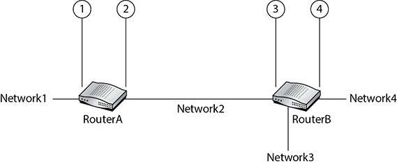
FIGURE 10-1 Standard ACL topology example
If we want to block traffic to Network4 from Network1, there are technically four locations that an ACL can be applied: the left interface of RouterA (pointed to by line 1 in Figure 10-1), the right interface of RouterA (pointed to by line 2 in Figure 10-1), the left interface of RouterB (pointed to by line 3 in Figure 10-1), and the right interface of RouterB (pointed to by line 4 in Figure 10-1). If traffic is being sent from Network1, it’s considered inbound traffic to the left interface of RouterA and outbound traffic from the right interface of RouterA. It’s also considered inbound traffic to the left interface of RouterB and outbound traffic to the right interface of RouterB.
If we apply the standard ACL inbound on the left interface of RouterA, this will block all traffic from Network1, regardless of whether it’s destined for Network4, so that’s not a good idea. If we apply the ACL outbound on the right interface of RouterA, this would block all traffic from Network1 destined for any network in that direction. If RouterA had other interfaces open (not shown in Figure 10-1), Network1 traffic would still be able to leave those interfaces. We wouldn’t make the ACL inbound on the left interface of RouterB, as that would block traffic from Network1 to Network3 too. Furthermore, if another interface is connected to a network on RouterB in the future, traffic from Network1 would be blocked from it, too. The recommendation is to place standard ACLs as close as possible to the destination (not just router but interface, too) so that traffic doesn’t get filtered unnecessarily. In this case, it’s an outbound ACL on the right interface of RouterB.
Direction is very important. For example, applying an ACL that blocks traffic from Network1 as an inbound list on the right interface of RouterB results a logic error. The ACL would be worthless because traffic sourced by Network1 will never go inbound to the right interface of RouterB, only outbound.
We say that stateless packet filters permit or deny packets from entering or exiting a network. However, when we are configuring an ACL and applying it to an interface, the direction, either inbound or outbound, is always in relation to the router, which will always be the opposite direction for the network. Traffic outbound from a network is inbound to a router. Traffic inbound to a network is outbound from a router. Furthermore, only one ACL can be applied per direction per interface. In other words, an interface can have just one inbound ACL and just one outbound ACL. That means the maximum number of ACLs per interface is two.
This lab exercise continues with the topology established in the previous chapter. If you haven’t completed that chapter, you must go back and complete it before attempting the lab exercises in this chapter. Furthermore, some of the instructions assume you learned how to move around the different modes of the routers, as well as navigate the devices in the Packet Tracer topology from the previous chapter.
![]() Note
Note
Press ENTER after each command.
![]() 1a–1n
1a–1n
Step 1 Configure, apply, and test a standard ACL that denies an entire subnet.
a. From PC0 (10.1.0.100) and PC1 (10.1.0.1), ping PC2 (10.4.0.2) and PC3 (10.4.0.3). All four pings should be successful.
b. On Router2, go into global configuration mode.
c. Enter access-list 1 deny 10.1.0.0 0.0.255.255 to deny all traffic originating from the 10.1.0.0/16 subnet.
d. Enter access-list 1 permit any to permit any other traffic that doesn’t meet the preceding statement.
e. Enter interface GigabitEthernet0/0/0 to go into interface configuration mode for that interface.
f. Enter ip access-group 1 out to apply the ACL as an outbound list on interface GigabitEthernet0/0/0. Standard ACLs should be placed as close as possible to the destination to prevent unnecessary filtering. This means not only the router closest to the destination, but the interface as well.
g. Enter END to go back to enable mode.
h. Enter show access-lists to see the ACL.
i. Enter show ip interface GigabitEthernet0/0/0 to see that the list is applied to the GigabitEthernet0/0/0 interface as an outbound ACL. You’ll notice a line close to the top that reads “Outgoing access list is 1.” Advance line by line by pressing ENTER or page by page by pressing SPACEBAR. Break out with SPACEBAR.
j. Enter show running-config to see the running configuration of this router, which includes the ACL statements.
k. From PC0 (10.1.0.100) and PC1 (10.1.0.1), ping PC2 (10.4.0.2) and PC3 (10.4.0.3). All four pings should now be unsuccessful.
l. Go back to Router2. In enable mode, enter show access-lists, as before.
This time, you’ll notice that the output shows that there were 16 matches for the first ACL statement, and those packets were blocked. These were, of course, the four sets of four ICMP Echo Requests sent by PC0 (10.1.0.100) and PC1 (10.1.0.1).
m. From Router1, in either user EXEC or enable mode, execute ping 10.4.0.2 and ping 10.4.0.3. Both pings should be successful.
n. Go back to Router2, and in enable mode, enter show access-lists as before.
This time, you’ll notice that the output shows that there were 10 matches for the second ACL statement, and those packets were let into the network. These were, of course, the two sets of five ICMP Echo Requests sent by Router1. The routers send five ICMP Echo Requests by default, unlike the Windows PCs that send four.
Packets sourced by Router1’s GigabitEthernet 0/0/0 interface, 10.3.0.98, did not meet the first ACL statement that blocks traffic sourced from the 10.1.0.0/16 network. As a result, these packets met the second permit any statement and were let through.
If you want to reset the ACL counters and try this again, from enable mode enter the following command:
clear access-list counters
![]() 2a–2j
2a–2j
Step 2 Remove the standard ACL from the preceding step. Then, configure, apply, and test a new standard ACL that denies a single host.
a. From global configuration mode on Router2, enter no access-list 1 to remove the current ACL.
b. Enter access-list 1 deny 10.1.0.1 to block just PC1 from 10.4.0.0/16.
c. Enter access-list 1 permit any to permit any other traffic that doesn’t meet the preceding statement.
d. Enter END to go back to enable mode. The new access-list 1 is automatically applied as an outbound ACL to interface GigabitEthernet0/0/0 since we never removed the application of the previous access-list 1.
e. From PC0 (10.1.0.100), send pings to PC2 (10.4.0.2) and PC3 (10.4.0.3). The pings should succeed since just PC1 (10.1.0.1) is being blocked now, not the entire 10.1.0.0/16 subnet.
f. From PC1 (10.1.0.1), send pings to PC2 (10.4.0.2) and PC3 (10.4.0.3). The pings should fail since PC1 is being blocked now, not the entire 10.1.0.0/16 subnet.
g. Go back to Router2 and enter show access-lists. You’ll notice that each statement has eight matches. The first statement was matched from the two sets of four ICMP Echo Requests sent from PC1 (10.1.0.1), while the second statement was matched from the two sets of four ICMP Echo Requests sent from PC0 (10.1.0.100).
h. On Router2, in global configuration mode, enter no access-list 1 to remove the ACL.
i. In interface configuration mode of GigabitEthernet0/0/0, enter no ip access-group 1 out to remove the application of the ACL to interface g0/0/0.
![]() 60 MINUTES
60 MINUTES
Lab Exercise 10.03: Extended ACLs on Routers
Learning Objectives
In this lab exercise, you’ll go further in your exploration of filtering packets. At the end of this lab exercise, you’ll be able to
• Configure extended ACLs
• Test extended ACLs
• Modify extended ACLs
Lab Materials and Setup
The materials you need for this lab are
• The Principles of Computer Security: CompTIA Security+ and Beyond textbook
• A web browser with an Internet connection
• Completed lab exercises in Cisco Packet Tracer from the previous chapter
• One or more Cisco Ethernet switches with at least two PCs (optional, as an alternative to Packet Tracer)
Let’s Do This!
Extended ACLs can filter by three or four criteria: source IP, destination IP, protocol, and port, with port being the only optional parameter. This gives you more granular control over the rules.
Let’s say we want to block HostA from accessing the Apache Web Server on ServerA, but not any other services on ServerA, as shown in Figure 10-2.
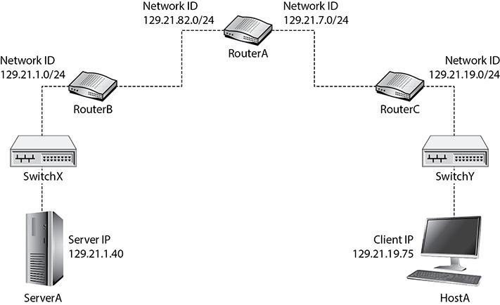
FIGURE 10-2 Extended ACL topology example
We need an extended ACL in this case. Let’s walk through an ACL that’s extended. The extended ACL statement starts off the same way as a standard ACL statement, with access-list.
For an extended ACL, the number of the ACL falls within the inclusive range of 100 to 199. In this case, we’re using 100. Next we have, just like in a standard ACL, the keyword permit or deny, depending on what we’re trying to do:
access-list 100 deny
That’s where the similarities end. At this point in the extended ACL statement, we need to specify a protocol. Common entries are TCP, UDP, ICMP, and IP. In our statement, we’re selecting TCP, which will only match traffic encapsulated in a TCP header, at Layer 4:
access-list 100 deny tcp
After that, there are two IP addresses preceded by the keyword host, as shown next. The first represents the source; the second represents the destination. Of course, each of those could’ve been written with the IP address first, followed by a wildcard mask of 0.0.0.0, as mentioned earlier. Extended ACL statements cannot leave off the wildcard mask for a host, even though standard ACL statements can.
access-list 100 deny tcp host 129.21.19.75 host 129.21.1.40
At this point, this ACL statement will in fact block all connection-oriented TCP-based traffic from the source 129.21.19.75 to the destination 129.21.1.40. This is not what we want, though. We just want to block the source from accessing the web server, but not any other service running on the machine. Maybe there’s an FTP server or an SSH server (FTP and SSH both use TCP at Layer 4). The source should be able to access these services.
Now we’re going to add the operator eq (equal to), in this case to achieve our desired result. Following eq is 80, as shown next. This means only filter traffic from source 129.21.19.75 to destination 129.21.1.40 if the TCP segment has a destination port of 80, meaning the traffic is destined for the web server on 129.21.1.40.
access-list 100 deny tcp host 129.21.19.75 host 129.21.1.40 eq 80
That might be a perfectly configured statement, but at this point our ACL blocks everything. Remember that if packets don’t match any ACL statements, they are denied, which means the router will filter/drop these packets. We’ve got to override the implicit statement at the end of every ACL for packets not meeting any explicitly configured statements.
The way we do that with an extended ACL is as follows: the syntax starts off with access-list 100, as explained before, followed with permit, as explained before. Now, however, instead of just the word any, like we saw with the standard ACL, we input ip any any, as shown here:
access-list 100 deny tcp host 129.21.19.75 host 129.21.1.40 eq 80
access-list 100 permit ip any any
Remember that an extended ACL’s only optional parameter is port, where the first statement is represented by eq 80. We need to include a protocol in every extended ACL statement. To include all protocols in the TCP/IP suite, simply enter ip. Anything encapsulated in an IP header matches ip.
What about the two instances of any? The first represents any source, and the second represents any destination. Now packets not meeting the first statement will match this second statement and will be filtered.
Extended ACLs should be applied as close to the source as possible. In our earlier example, that would mean the ACL would be applied as an inbound ACL on the right interface of RouterC. Why tie up bandwidth and processing power all the way from RouterC to RouterB if traffic from HostA will be blocked anyway? The logic is to filter it as early as possible. This couldn’t be done with the standard ACL, because the only criteria specified is the source IP address. However, if we apply an inbound ACL to the right interface of RouterC, blocking traffic from HostA to our web server, with the destination port of 80, all other traffic from HostA will be unfiltered.
This lab exercise continues with the topology established in the previous chapter. If you haven’t completed that chapter, you must go back and complete it before attempting the lab exercises in this chapter. Furthermore, some of the instructions assume you have learned how to move around the different modes of the routers as well as navigate the devices in the Packet Tracer topology from the previous chapter.
![]() Note
Note
Press ENTER after each command.
![]() 1a–1e
1a–1e
Step 1 Configure and apply an extended ACL that blocks specific traffic from a specified source IP address to a specified destination IP address over a specific port.
a. Go to global configuration mode on Router0.
b. Enter access-list 101 deny tcp 10.1.0.100 0.0.0.0 10.4.0.3 0.0.0.0 eq 80 to block just traffic from PC0 (10.1.0.100) to PC3 (10.4.0.3) over port 80.
c. Enter access-list 101 permit ip any any to allow through any traffic not meeting the preceding statement.
d. Enter interface GigabitEthernet0/0/1 to enter interface configuration mode.
e. Enter ip access-group 101 in to apply this ACL as an inbound list on interface GigabitEthernet0/0/1.
![]() 2a–2f
2a–2f
Step 2 Test the extended ACL from the previous step.
a. From PC0 (10.1.0.100), click the Desktop tab and then select Web Browser (at the end of the first row).
b. In the URL bar, enter 10.4.0.3 and click the Go button. You’ll see the message “Request Timeout.”
c. Go back to Router0, and in enable mode, enter show access-lists.
You’ll notice that the first statement has matches. These are the attempts to connect over the default HTTP port of 80 from 10.1.0.1.
d. Go back to PC0 (10.1.0.100). In the Web Browser URL bar, enter 10.4.0.3:99 to specify a non-default port of 99.
e. Now you’ll notice a different message, “Server Reset Connection,” since there is no service on PC3 (10.4.0.3) listening on port 99, which is a closed port.
f. Go back to Router0, and in enable mode, enter show access-lists. You’ll notice that the second statement now has a match. This is an attempt to connect with a TCP SYN over the non-default port of 99 from 10.1.0.1, which wasn’t blocked by the first ACL statement since the destination port wasn’t 80.
Lab Analysis
1. What are reasons for configuring port security?
![]()
2. What are the actions port security can take when violations occur?
![]()
3. What do standard ACLs filter by?
![]()
4. What do extended ACLs filter by?
![]()
5. Where should standard ACLs be placed?
![]()
6. Where should extended ACLs be placed?
![]()
7. How is the purpose of a wildcard mask different from that of a subnet mask?
![]()
8. What do inbound and outbound mean from an ACL perspective and how are they different from their normal usage?
![]()
Key Term Quiz
Use the terms from the list to complete the sentences that follow.
interface
MAC address
port
source IP address
1. Port security on switches can prevent a CAM overflow attack, making sure that only one ____________ is heard on a switch port.
2. Standard ACLs filter by ____________.
3. Extended ACLs can, but do not have to, filter by ____________.
4. There can be one inbound and one outbound ACL per ____________.