11
Prototyping Project (Clock)
In this chapter, we will build what can only be seen as a grossly over-engineered LED digital clock. We will be using a Raspberry Pi, a breadboard, and a four-digit LED display (see Figure 11-1).
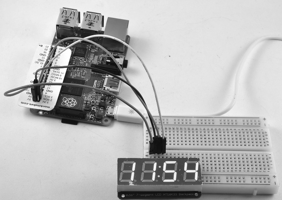
Figure 11-1 LED clock using the Raspberry Pi.
In the first phase of the design, the project will just display the time. However, a second phase extends the project by adding a push button that, when pressed, switches the display mode between displaying hours/minutes, seconds, and the date.
What You Need
To build this project, you will need the following parts. Suggested part suppliers are listed, but you can also find these parts elsewhere on the Internet.
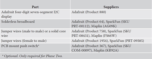
The breadboard, jumper wires, and switch are all included in the Project Box 1 Kit for Raspberry Pi by MonkMakes.
Hardware Assembly
The LED display module is supplied as a kit that must be soldered together before it can be used. It is easy to solder, and detailed step-by-step instructions for building it can be found on the Adafruit website. The module has pins that just push into the holes on the breadboard.
The display has just four pins (VCC, GND, SDA, and SCL) when it is plugged into the breadboard; align it so that the VCC pin is on row 1 of the breadboard.
Underneath the holes of the solderless breadboard are strips of connectors, linking the five holes of a particular row together. Note that because the board is on its side, the rows actually run vertically in Figure 11-2.
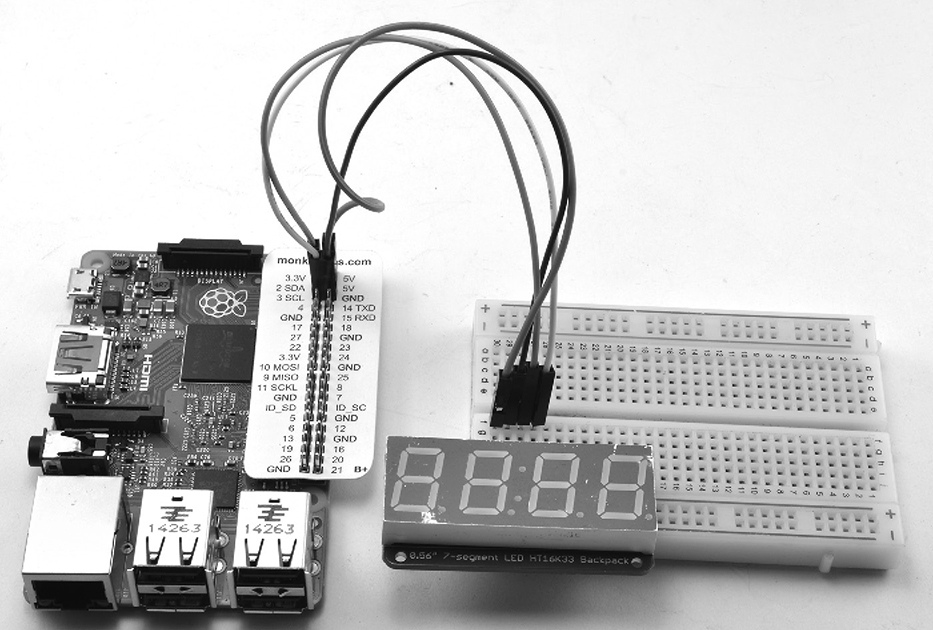
Figure 11-2 Breadboard layout.
Figure 11-2 shows the solderless breadboard with the four pins of the display at one end of the breadboard.
The connections that need to be made are listed here:

The color scheme shown in this table is only a suggestion; however, it is common to use red for a positive supply and black or blue for the ground connection.
CAUTION In this project, we are connecting a 5V display module to the Raspberry Pi, which generally uses 3.3V. We can only safely do this because the display module used here only acts as a “peripheral” device and hence only listens on the SDA and SCL lines. Other I2C devices may act as a controller device, and if they are 5V, there is a good chance this could damage your Pi. Therefore, before you connect any I2C device to your Raspberry Pi, make sure you understand what you are doing.
Turn on the Raspberry Pi. If the usual LEDs do not light, turn it off immediately and check all the wiring.
Software
Everything is connected, and the Raspberry Pi has booted up. However, the display is still blank because we have not yet written any software to use it. We are going to start with a simple clock that just displays the Raspberry Pi’s system time. The Raspberry Pi does not have a real-time clock to tell it the time. However, it will automatically pick up the time from a network time server if it is connected to the Internet.
The Raspberry Pi displays the time in the top-right corner of the screen.
You may find that the minutes are correct but that the hour is wrong. This probably means that your Raspberry Pi does now know which time zone it is in. This can be fixed by setting the time zone from the Raspberry Pi Configuration tool that you will find in the Configuration section of the Raspberry Pi Menu (Figure 11-3).
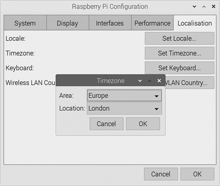
Figure 11-3 Setting your Raspberry Pi’s time zone.
By default, the I2C interface that the display uses is disabled, so before we can use the display we need to enable it by going to the Raspberry Pi Configuration tool in the Preferences menu and click on the Enabled button next to I2C (see Figure 11-4) and then click OK.
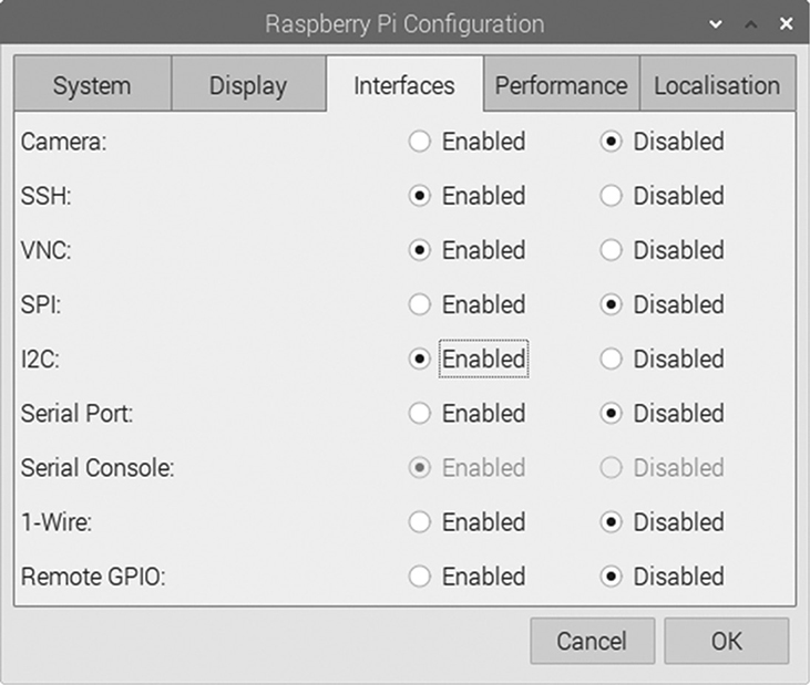
Figure 11-4 Enabling the I2C interface.
So now that the Raspberry Pi knows the correct time and the I2C bus is available, we can write a Python program that sends the time to the display. Adafruit has created some Python code to go with their I2C displays, in fact they have a very useful collection of all their Raspberry Pi code that is contained in a library called blinka that you need to download and install using the commands:
![]()
When you run the program 11_01_clock.py the LEDs should light up and display the correct time.
You can find the basic clock program in 11_01_clock.py.
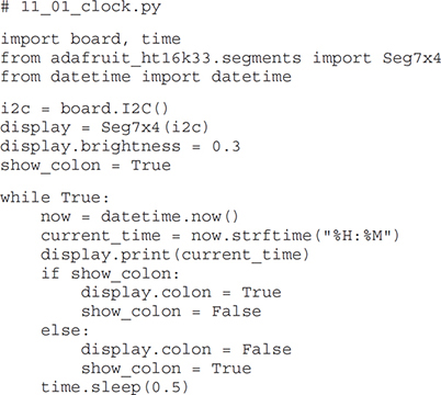
The program starts by importing the things it needs from the Adafruit libraries to control the display. It also imports datetime which allows us to get hold of the date and time from the Raspberry Pi so that we can use it in the clock program.
The display modules uses the I2C interface for the Raspberry Pi. This interface is assigned to a variable called i2c that is then passed as a parameter to the constructor of the Adafruit class Seg7x4 that acts as an interface to the display itself.
The brightness of the display can be set to a value between 0 and 1. Here, it has been set to one-third brightness, as these displays are pretty bright.
The variable show_colon is used to keep track of whether the colon is currently being shown, so that we can make it reblink in time with the seconds changing.
The main while loop gets the current time from the Raspberry Pi and formats it into hours and minutes, before telling the display to show it. The colon is toggled between on and off and a delay of half a second on the last line of the program ensures that the colon changes between on and off every half second.
Phase Two
Having got the basic display working, let’s expand both the hardware and software by adding a button that changes the mode of the display, cycling between the time in hours and minutes, the seconds, and the date. Figure 11-5 shows the breadboard with the switch added as well as two new patch wires. Note that we are just adding to the layout of the first phase by adding the button; nothing else is changed.
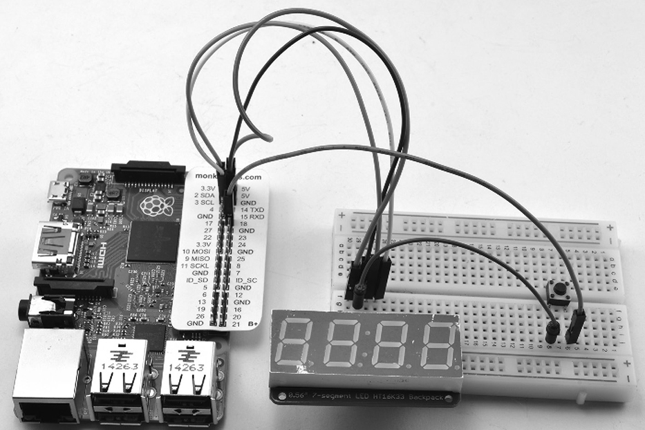
Figure 11-5 Adding a button to the design.
NOTE Shut down and power off your Pi before you start making changes on the breadboard.
The button has four leads and must be placed in the right position; otherwise, the switch will appear to be closed all the time. The leads should emerge from the sides facing the top and bottom of Figure 11-5. Don’t worry if you have the switch positioned in the wrong way—it will not damage anything, but the display will continuously change mode without the button being pressed.
Two new wires are needed to connect the switch. One goes from one lead of the switch (refer to Figure 11-5) to the GND connection of the display. The other lead goes to the connection labeled 18 on the GPIO connector. The effect is that whenever the button on the switch is pressed, the Raspberry Pi’s GPIO 18 pin will be connected to ground.
You can find the updated software in the file 11_02_fancy_clock.py and listed here:

The first thing to notice is that because we need access to GPIO pin 18 to see whether the button is pressed, we need to use the gpiozero library.
Most of what was in the loop has been separated into a function called display_time. Also, two new functions have been added: display_seconds and display_date. These are fairly self-explanatory.
One point of interest is that display_date displays the date in U.S. format. If you want to change this to the international format, where the day of the month comes before the month, change the format on line 36 to %d%m.
To keep track of which mode we are in, we have added some new variables in the following lines:
![]()
The first of these lines gives each of the three variables a different number. The second line sets the disp_mode variable to the value of time_mode, which we use later in the main loop.
The main loop has been changed to determine whether the button is pressed. If it is, then 1 is added to disp_mode to cycle the display mode. If the display mode has reached the end, it is set back to time_mode.
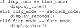
Finally, the if blocks that follow select the appropriate display function, depending on the mode, and then call it.
Summary
This project’s hardware can quite easily be adapted to other uses. You could, for example, present all sorts of things on the display by modifying the program. Here are some ideas:
![]() Your current Internet bandwidth (speed)
Your current Internet bandwidth (speed)
![]() The number of e-mails in your inbox
The number of e-mails in your inbox
![]() A countdown of the days remaining in the year
A countdown of the days remaining in the year
![]() The number of visitors to a website
The number of visitors to a website
In the next chapter, we build another hardware project—this time a roving robot—using the Raspberry Pi as its brain.