
CHAPTER 20
Dissecting Embedded Devices
In this chapter, we cover the following topics:
• CPU
• Serial interfaces
• Debug interfaces
• Software
This chapter provides a high-level view of embedded devices with the intention of providing a vocabulary for and high-level understanding of potential areas of concern. Embedded devices are electrical or electro-mechanical devices that meet a specific need or have a limited function. A few examples of embedded devices include security systems, network routers/switches, cameras, garage door openers, smart thermostats, controllable light bulbs, and mobile phones. As our devices gain remote connectivity for our convenience, they also provide more opportunity for an attacker to enter our lives through our networks.
Much of the discussion in this chapter revolves around integrated circuits (ICs). An IC is a collection of electrical components within a small package, often referred to as a chip. A simple example is the quad 2-input OR1 gate IC, where four 2-input OR circuits are implemented inside a single chip. In our case, the ICs will be much more complex and contain the entire multiple-computing elements inside a single IC. Also, note that this chapter assumes you are familiar with a multimeter and the basic concepts of electrical circuits, such as voltage, current, resistance, and ground.
CPU
Unlike the desktop systems that most people are familiar with, the embedded world uses many different processing architectures based on embedded functionality, required complexity of the system, price, power consumption, performance, and other considerations. Because embedded systems generally have much more defined functionality, they tend to lend themselves to more quantifiable performance requirements. As a result, a blend of software and hardware requirements are used to determine the appropriate microprocessor, microcontroller, or system on chip (SoC).
Microprocessor
Microprocessors do not include memory or program storage internal to the chip. Microprocessor-based designs can utilize a large amount of memory and storage and can run sophisticated operating systems such as Linux. The common PC is an example of a device utilizing a microprocessor-based design.
Microcontrollers
Common within the embedded world is the microcontroller. The microcontroller generally has a CPU core (or cores), memory, storage, and I/O ports, all within a single chip. The microcontroller is well suited to highly embedded designs that perform simple or well-defined lower-performance applications. Due to the simplicity of the applications and hardware, the software on the microcontroller is typically written in a lower language such as assembly or C and does not include an operating system (OS). Applications for a microcontroller include an electronic door lock and a TV remote.
Depending on the specific microcontroller, protections may be implemented in hardware to help secure the applications. Examples are read protections for the program storage and disabling the on-chip debugging interface from becoming active. Although these measures provide a layer of protection, there are no guarantees that the protections cannot be bypassed.
System on Chip
The System on Chip (SoC) is one or more microprocessor cores or microcontrollers with a wide variety of integrated hardware features within a single integrated circuit (IC). For example, the SoC for a phone may contain a graphics processing unit (GPU), sound processor, memory management unit (MMU), cellular, and network controller. The main benefit of the SoC is reduced cost due to fewer chips and smaller-size applications, which are typically used in a more custom fashion. Whereas a microcontroller stores the program internally and provides limited memory, the SoC typically utilizes external storage and memory.
Common Processor Architectures
Although there are many microcontroller architectures, such as Intel 8051, Freescale (Motorola) 68HC11, and Microchip PIC, two architectures show up much more in Internet-connected devices: ARM and MIPS. Knowing the processor architecture is important when using tools such as disassemblers, build tools, and debuggers. Identification of the processor architecture can typically be done by visually inspecting the board and locating the processor.
ARM is a licensed architecture that is used by many microprocessor, microcontroller, and SoC manufacturers such as Texas Instruments, Apple, Samsung, and more. The ARM cores are licensed in multiple profiles based on the intended applications. ARM cores come in both 32- and 64-bit architectures and can be configured as either big- or little-endian. Table 20-1 illustrates the profiles and applications that would typically use them.
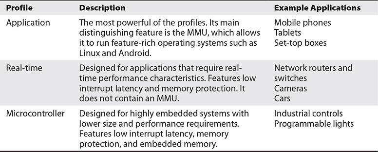
Table 20-1 ARM Profiles2
MIPS, last owned by Wave Computing, which recently came out of bankruptcy, is no longer being developed in favor of RISC-V; however, license agreements signed prior to restructuring appear to be valid.3 MIPS has been licensed to several manufacturers, such as Broadcom, Cavium, and others. Like ARM, MIPS has 32- and 64-bit variants and can be run in either big- or little-endian mode. It is commonly found in networking devices such as wireless access points and small home routers.
Serial Interfaces
A serial interface communicates with a peer one bit at a time, serially, over a communication channel. Being that only one bit is being transmitted at a time, fewer pins are required on an IC. In contrast, parallel interface communications transmit multiple bits at a time and require more pins (one pin per bit). Several serial protocols are used in embedded systems, but we will only discuss the Universal Asynchronous Receiver-Transmitter (UART), Serial Peripheral Interface (SPI), and Inter-Integrated-Circuit (I2C) protocols.
UART
The Universal Asynchronous Receiver-Transmitter protocol allows two devices to communicate serially over a communications channel. UART is commonly used for connecting to a console to allow a human to interact with the device. Although most devices will not have an externally available interface for communicating serially, many will have an internal interface that was used during device development and testing. While performing device testing, I have found both authenticated and unauthenticated consoles on internally accessible serial interfaces.
UART requires three pins to communicate and usually comes in a gang of four pins (see Figure 20-1). You may see labels on the board, but generally these pads or headers are not labeled and need to be discovered. Although Figure 20-1 shows a nice example where the headers stand out as candidates for serial communications, the layout of the pins might not always be as straightforward and could be mingled within a larger number of pins.
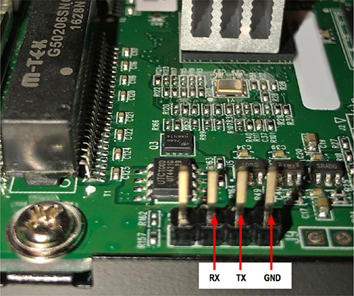
Figure 20-1 Unlabeled gang of four serial ports on a Ubiquiti ER-X
The main reason for locating and connecting to the internal serial ports is to attempt to locate information that was not intended to be accessible to the user of the system. For example, the web interface does not generally yield access to the file system directly, but the serial console on a Linux-based system will give the user access to the file system. When the serial port is authenticated, you will have to brute-force the credentials or attempt to bypass the authentication by altering the boot process (potentially by using a JTAG debug port).
To discover the serial pads, a tool such as JTAGulator, developed by Joe Grand, can be used to brute-force signals and yield the pad layout and baud rate. The following is an example of running the UART identification test against the Ubiquiti ER-X shown in Figure 20-1, where the labeled pins were identified using JTAGulator. Here are the steps involved:
1. Locate the headers or pads you believe could be UART by inspecting the board. (Seeing two to four pads/pins grouped together on the board is a good sign, but as mentioned earlier, they can be intermingled within other functional pads/pins.)
2. Discover the target voltage by probing the board with a multimeter or identifying an IC and looking up the datasheet.
3. Discover a ground that is easy to connect to by measuring resistance (ohms) between a known ground (such as the chassis ground) and pins that are easy to connect to (effectively 0 ohms between the known ground and the pin in question).
4. Connect the board to your JTAGulator if you are fortunate enough to find headers, or solder a header to the board and then connect (see Figure 20-2).

Figure 20-2 Connection between JTAGulator and Ubiquiti ER-X
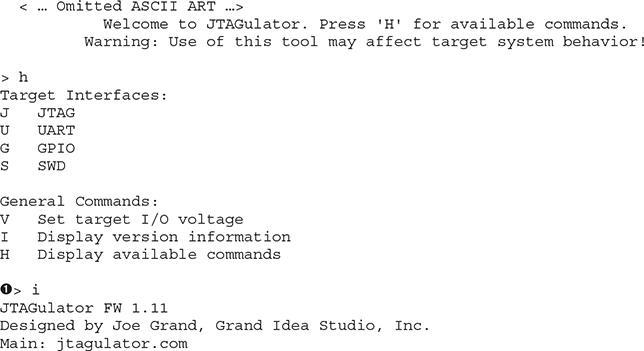
5. Verify the version of JTAGulator firmware ![]() . The version can be checked against the code on the repository at https://github.com/grandideastudio/jtagulator/releases. If the version is not the latest, follow the directions at www.youtube.com/watch?v=xlXwy-weG1M.
. The version can be checked against the code on the repository at https://github.com/grandideastudio/jtagulator/releases. If the version is not the latest, follow the directions at www.youtube.com/watch?v=xlXwy-weG1M.
6. Enable UART mode ![]() and set the target voltage
and set the target voltage ![]() .
.
7. Run the UART identification test ![]() .
.
8. On success, look for reasonable responses such as carriage returns, line feeds, or readable text ![]() (l-timers(q) sync).
(l-timers(q) sync).
9. Verify the identified settings by running in pass-thru mode ![]() with the baud rate candidate
with the baud rate candidate ![]() (57600 in our case).
(57600 in our case).
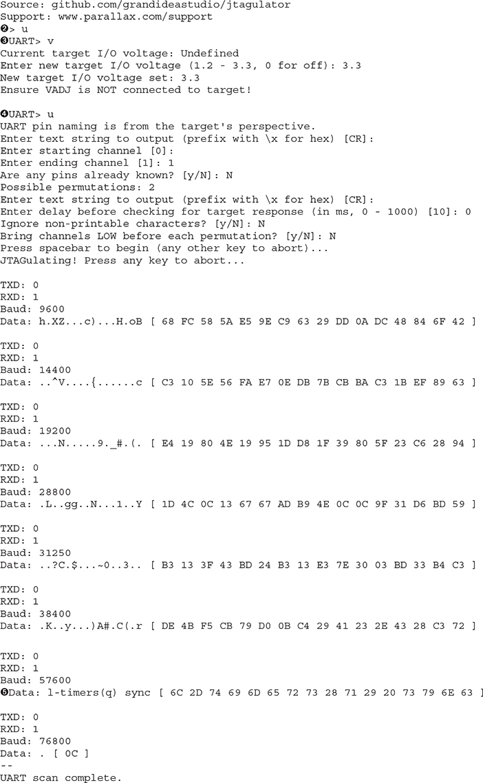
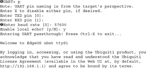
If the test is successful, you should be able to interact with the serial console now. Resetting the device with the serial console connected is typically very revealing. The text is too long to include here, so I’ve provide snippets from the boot messages:
• The processor is an MT-7621A (MIPS):
ASIC MT7621A DualCore (MAC to MT7530 Mode)
• It can be reprogrammed via U-Boot:
• It is running Linux version 3.10.14-UBNT:
![]()
• MTD partitions aid in understanding the storage layout:
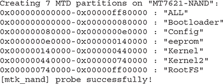
Once the layout is determined, you can use a tool such as Bus Pirate to connect to the pads and communicate with the embedded system. The main thing to remember is to connect the TX on the device to the RX of your Bus Pirate and to connect the RX on the device to the TX of your Bus Pirate.
As with the JTAG interface, some may discount the severity of having enabled serial ports on a device. However, with console access, an attacker can extract the configuration and binaries, install tools, and look for global secrets that facilitate remote attacks against all devices of this type.
SPI
Serial Peripheral Interface (SPI) is a full-duplex synchronous serial interface that is popular in embedded systems. Unlike UART, SPI was designed to allow communications between two or more devices. SPI is a short-distance protocol that is used for communications between ICs within an embedded system. The protocol uses a master/slave architecture and supports multiple slaves.4 In its simplest form, SPI requires four pins to communicate, which puts it on par with the UART example but with faster communications (at the cost of distance). It is important to note that SPI is not standardized,5 and the datasheets will need to be consulted to determine the exact behavior of each device. The four pins are as follows:
• SCK Serial Clock
• MOSI Master Out Slave In
• MISO Master In Slave Out
• SS or CS Slave/Chip Select (output from master to address slave; active low)
For systems with a few slave devices, the master typically addresses each slave device using a dedicated chip select. Due to the additional chip selects, this requires more pins/traces and increases the cost of the system. For example, a system with three slave devices in this configuration requires six pins on the microcontroller (see Figure 20-3).
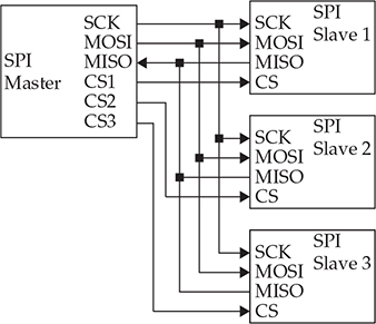
Figure 20-3 SPI in a three-chip configuration with individual chip selects
Another common configuration for multiple-slave devices is the daisy chain.4 The daisy chain configuration, shown in Figure 20-4, is typically used when the master does not need to receive data for applications such as LEDs or when there are many slave devices. Because the output of chip 1 is connected to the input of chip 2, and so on, there is a delay proportionate to the number of chips between the master and the intended recipient.

Figure 20-4 SPI in a three-chip configuration using a daisy chain
A common use of the SPI protocol is to access EEPROM (electrically erasable programmable read-only memory) and flash devices. By using Bus Pirate and flashrom (or something similar), you should be able to extract the contents of an EEPROM or flash device. The contents can then be analyzed to locate the file system and hunt for secrets.
I2C
Inter-Integrated-Circuit, pronounced I-squared-C and written as I2C,6 is a multimaster, multislave, packetized serial communications protocol. It is slower than SPI but only uses two pins instead of three, plus chip selects for each slave. Like SPI, I2C is used for short distances between ICs on the board, but it can be used in cabling. Unlike SPI, I2C is an official specification.
Although multiple masters are supported, they cannot communicate with each other and cannot use the bus at the same time. To communicate with a specific device, the master uses an address packet, followed by one or more data packets. The two pins are as follows:
• SCL Serial Clock
• SDA Serial Data
From Figure 20-5, you can see that the SDA pin is bidirectional and shared for all devices. Additionally, the SCL pin is driven by the master that has acquired the data bus.
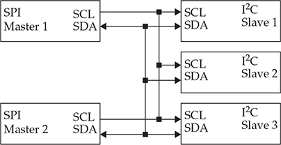
Figure 20-5 A two-master, three-slave sample configuration
Like SPI, I2C is commonly used to communicate with EEPROM or NVRAM (nonvolatile random access memory). By using something like the Bus Pirate, you can dump the contents for offline analysis or write new values.
Debug Interfaces
Whereas debugging an application on a computer running Windows or Linux is relatively easy, by simply attaching to a process with a software debugger, embedded systems have many obstacles that make such a process a bit trickier. For example, how do you debug the embedded system when there is no operating system or the operating system is not booted? Modern embedded systems also have many complicated ICs on potentially densely populated boards with little to no access to the pins on the chips. Fortunately for the developers and testers, the hardware manufacturing industry developed methods for accessing IC internals for testing, debugging, and writing firmware to nonvolatile storage, and many other uses.
JTAG
The Joint Test Action Group (JTAG) was created in the 1980s as a method to facilitate debugging and testing ICs. In 1990, the method was standardized as IEEE 1149.1, but it is commonly referred to as simply JTAG.7 Although it was initially created to help with board-level testing, the capabilities allow debugging at the hardware level.
Although this is an oversimplification, JTAG defines a mechanism of utilizing a few externally accessible signals to access IC internals via a standardized state-machine. The mechanism is standardized, but the actual functionality behind it is IC specific. This means that you must know the IC being debugged to use JTAG effectively. For example, a bit sequence to an ARM processor and an MIPS processor will be interpreted differently by the internal logic of the processor. Tools such as OpenOCD require device-specific config files to operate properly. Although manufacturers may define more pins, the four/five JTAG pin description is provided in Table 20-2. The collection of pins is also known as the test access port (TAP).
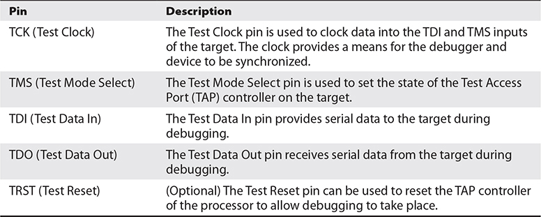
Table 20-2 Four/Five Pin JTAG Interface Description
Although you might think that five pins would have a standard layout, board and IC manufacturers define their own layouts. Some common pinouts are defined in Table 20-3 and include 10-, 14-, and 20-pin configurations. The pinouts in the table are only a sampling and need to be verified before they are used with a debugger.
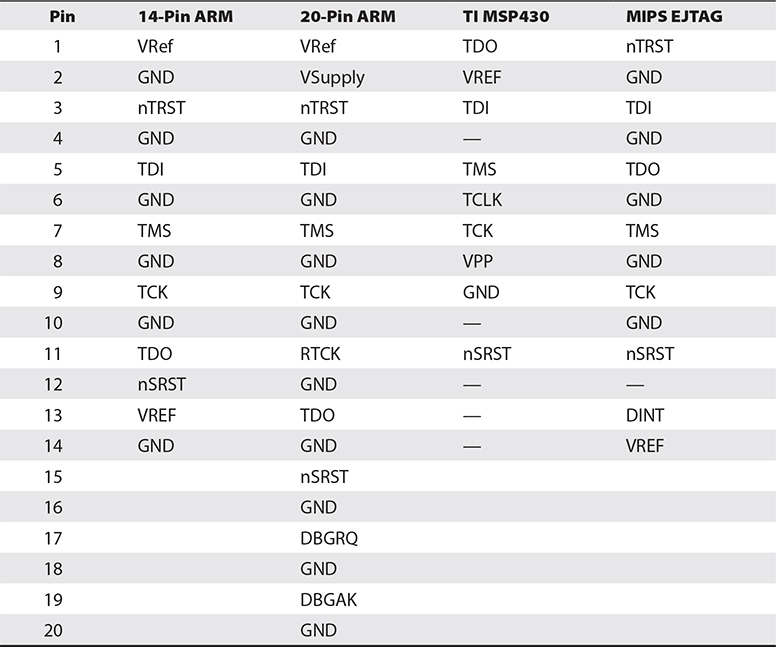
Table 20-3 Typical JTAG Pinouts8, 9
For the developer and tester, the following capabilities are commonly used:
• Halting the processor while debugging
• Reading and writing the internal program store (when code is stored inside the microcontroller)
• Reading and writing flash (firmware modification or extraction)
• Reading and writing memory
• Modifying the program flow to bypass functionality to gain restricted access
As you can see, the functionality available to the JTAG interface is quite powerful. Equipment manufacturers are in a quandary. To develop, test, and debug the embedded system throughout its life cycle, the JTAG port is indispensable; however, its existence on the board provides researchers and attackers the ability to discover secrets, alter behavior, and find vulnerabilities. Manufacturers will typically attempt to make it more difficult to use the JTAG interface after production by severing the lines, not populating the pins, not labeling the pinout, or using chip capabilities to disable it. Although this is reasonably effective, a determined attacker has many means in their arsenal to circumvent the protections, including fixing broken traces, soldering pins on the board, or possibly even shipping an IC to a company that specializes in extracting data.
Some may dismiss JTAG as a weakness since physical, possibly destructive, access is required to use it. The problem with dismissing the attack is that the attacker can learn a great deal about the system using JTAG. If a global secret such as a password, an intentional backdoor for support, a key, or a certificate is present on the system, it may be extracted and subsequently used to attack a remote system.
SWD
Serial Wire Debug (SWD) is an ARM-specific protocol for debugging and programming. Unlike the more common five-pin JTAG, SWD uses two pins. SWD provides a clock (SWDCLK) and bidirectional data line (SWDIO) to deliver the debug functionality of JTAG. As can be seen in Table 20-4, SWD and JTAG can coexist,10 which is important to note.
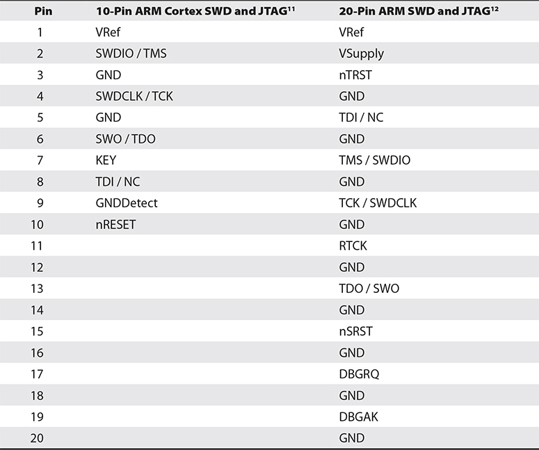
Table 20-4 Typical JTAG/SWD Pinouts
The capabilities for developers and testers are the same as those mentioned for JTAG. As with JTAG, the capabilities that help manufacturers also enable attackers to discover vulnerabilities.
Software
All the hardware we’ve discussed so far would be useless without something defining its functionality. In microcontroller/microprocessor-based systems, software defines the capabilities and breathes life into the system. A bootloader is used to initialize the processor and start the system software. The system software for these systems typically falls into one of these three scenarios:
• No operating system For simple systems
• Real-time operating system For systems with rigid processing time requirements (for example, VxWorks and Nucleus)
• General operating system For systems that typically don’t have hard time constraints and have many functional requirements (for example, Linux and Embedded Windows)
Bootloader
For higher-level software to run on a processor, the system must be initialized. The software that performs the initial configuration of the processor and the required initial peripheral devices is called the bootloader. The process typically requires multiple stages to get the system ready to run the higher-level software. The oversimplified process is generally described as follows:
1. The microprocessor/microcontroller loads a small program from a fixed location of an off-processor device based on the boot mode.
2. The small program initializes RAM and structures required to load the remainder of the bootloader in RAM (U-Boot, for example).
3. The bootloader initializes any devices necessary to start the main program or OS, loads the main program, and transfers execution to the newly loaded program. For Linux, the main program would be the kernel.
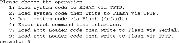
If U-Boot is used, this bootloader may have been configured to allow alternative means of loading the main program. For example, U-Boot is capable of loading from an SD card, NAND or NOR flash, USB, a serial interface, or TFTP over the network if networking is initialized. In addition to loading the main program, it can be used to replace the main program in a persistent storage device. The Ubiquiti ER-X, from our earlier example of using the JTAGulator, uses U-Boot (see Figure 20-6). In addition to loading the kernel, it allows reading and writing memory and storage.
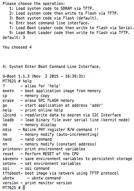
Figure 20-6 U-Boot from Ubiquiti ER-X
No Operating System
For many applications, the overhead of an OS and the simplicity of the system do not justify or allow for an OS. For example, a sensor that performs measurements and sends them to another device likely uses a low-power microcontroller such as a PIC and has very little need for an operating system. In this example, the PIC likely does not have enough resources (storage, RAM, and so on) to allow it to run an OS.
In systems with no OS, the data storage will likely be very crude, based on address offsets or using NVRAM. Additionally, these systems typically do not have a user interface, or the interface is extremely simple, such as LEDs and buttons. After the program has been acquired, either from extraction from storage or via downloading, the format can be entirely custom and not easily identifiable to frequently used file analysis tools. The best bet is to read the documentation for the microcontroller to understand how the device loads code and attempts to deconstruct it manually with a disassembler.
You might be thinking that a system this simple would not be very interesting, but keep in mind that it might have connectivity to a more complex system with Internet connections. Don’t dismiss these devices as not having a valuable attack surface without first considering the total use case, including connected devices and their purpose. The limited instruction space might mean that the device doesn’t have the ability to adequately protect itself from malicious input, and the protocols are likely not encrypted. Additionally, connected systems might explicitly trust any data coming from these devices and therefore not take appropriate measures to ensure that the data is valid.
Real-Time Operating System
Systems that are more complex and have hard time-processing requirements will typically use a real-time operating system (RTOS) such as VxWorks. The advantage of the RTOS is that it provides the functionality of an OS, such as tasks, queues, networking stacks, file systems, interrupt handler, and device management, with the added capability of a deterministic scheduler. For example, autonomous or driver-assisted automotive systems likely use an RTOS to ensure that reactions to various sensors are happening within the safety tolerance of the system (rigid).
For those used to systems running Linux, VxWorks is much different. Linux has a fairly standard file system with common programs such as telnet, BusyBox, ftp, and sh, and applications run as separate processes on the OS. With VxWorks, many of the systems run with effectively a single process, with multiple tasks and no standard file system or secondary applications. Whereas Linux has a lot of information regarding extraction of firmware and reverse engineering, there is very little information regarding VxWorks.
Extracting the firmware with SPI or I2C or using a downloaded file will provide you with strings and code that can be disassembled. But unlike with Linux, you will not generally get easily digestible data. Analyzing the strings for passwords, certificates, keys, and format strings can yield useful secrets to use against the live system. Additionally, using JTAG to set breakpoints and perform actions on the device is likely the most effective method of reversing the functionality.
General Operating System
The term general operating system is being used to describe non-RTOS operating systems. Linux is the most common example of a general operating system. Linux for embedded systems is not much different from Linux for a desktop system. The file systems and architecture are the same. The main differences between embedded and desktop versions are peripherals, storage, and memory constraints.
To accommodate the generally smaller storage and memory, the OS and file system are minimized. For example, instead of using the common programs installed with Linux, such as bash, telnetd, ls, cp, and such, a smaller monolithic program called BusyBox is typically used. BusyBox13 provides the functionality within a single executable by using the first argument as the desired program. Although I’d like to say that unused services are removed to reduce the attack surface, they are likely only removed to save space.
Although most devices do not intentionally provide console access to the user, many do have a serial port for console access on the board. As soon as you have access to the root file system, either via the console or by extracting the image from storage, you will want to look for the versions of applications and libraries, world-writable directories, any persistent storage, and the initialization process. The initialization process for Linux, found in /etc/inittab and /etc/init.d/rcS, will give you an idea of how the applications are started on boot.
Summary
In this chapter, we briefly discussed the differences between different CPU packages (microcontroller, microprocessor, and SoC), several serial interfaces of interest, JTAG, and embedded software. In our discussion of serial interfaces, you were introduced to the JTAGulator in an example of discovering UART (serial) ports. JTAGulator can also be used to discover JTAG debug ports and potentially several other interfaces. We also briefly discussed different software use cases, including bootloaders, no OS, an RTOS, and a general OS. At this point, you should have a common vocabulary for embedded systems and a few areas of concern when attempting to gain a further understanding.
For Further Reading
ARM developer.arm.com/products/architecture/a-profile, developer.arm.com/products/architecture/r-profile, developer.arm.com/products/architecture/m-profile, www.arm.com/products/silicon-ip-cpu
Bus Pirate dangerousprototypes.com/docs/Bus_Pirate
Embedded Linux www.elinux.org/Main_Page
Firmware extraction and reconstruction www.j-michel.org/blog/2013/09/16/firmware-extraction-and-reconstruction
Free RTOS www.freertos.org/
I2C learn.sparkfun.com/tutorials/i2c
JTAG wrongbaud.github.io/posts/jtag-hdd/, developer.arm.com/docs/dui0499/latest/arm-dstream-target-interface-connections/signal-descriptions/serial-wire-debug
JTAGulator www.grandideastudio.com/jtagulator/
MT-7621A www.mediatek.com/products/homeNetworking/mt7621n-a, wikidevi.wi-cat.ru/Ubiquiti_Networks_EdgeRouter_X_(ER-X)
OpenOCD openocd.org/
Reverse-engineering VxWorks firmware www.devttys0.com/2011/07/reverse-engineering-vxworks-firmware-wrt54gv8/
SPI www.maximintegrated.com/en/app-notes/index.mvp/id/3947
Understanding ARM HW debug options elinux.org/images/7/7f/Manderson5.pdf
VxWorks www.windriver.com/products/vxworks/
References
1. “OR gate,” Wikipedia, https://en.wikipedia.org/wiki/OR_gate.
2. “ARM Architecture Profiles,” ARM Developer, http://infocenter.arm.com/help/index.jsp?topic=/com.arm.doc.dui0471i/BCFDFFGA.html.
3. Jim Turley, “Wait, What? MIPS Becomes RISCV,” EE Journal, March 8, 2021, https://www.eejournal.com/article/wait-what-mips-becomes-risc-v/.
4. “Serial Peripheral Interface (SPI),” Sparkfun, https://learn.sparkfun.com/tutorials/serial-peripheral-interface-spi.
5. “Serial Peripheral Interface, Standards,” Wikipedia, https://en.wikipedia.org/wiki/Serial_Peripheral_Interface#Standards.
6. “I2C—What’s That?,” I2C, https://www.i2c-bus.org/.
7. “Joint Test Action Group,” Wikipedia, https://en.wikipedia.org/wiki/JTAG.
8. “JTAG Pinouts,” JTAG Test, www.jtagtest.com/pinouts/.
9. “JTAG Pin Descriptions,” ARM DS-5 ARM DSTREAM System and Interface Design Reference Guide, Version 5, https://developer.arm.com/docs/dui0499/latest/arm-dstream-target-interface-connections/the-arm-jtag-20-connector-pinouts-and-interface-signals/arm-jtag-20-interface-signals.
10. “Structure of the SWJ-DP” (JTAG/SWD Coexist as SWJ-DP), ARM Developer, http://infocenter.arm.com/help/index.jsp?topic=/com.arm.doc.ddi0314h/Chdjjbcb.html.
11. “10-Way Connector Pinouts” (SWD/JTAG 10 Pin), ARM Developer, http://infocenter.arm.com/help/index.jsp?topic=/com.arm.doc.ddi0314h/Chdhbiad.html.
12. “20-Way Connector Pinouts Including Trace” (SWD/JTAG 20 Pin), ARM Developer, http://infocenter.arm.com/help/topic/com.arm.doc.ddi0314h/Chdfccbi.html.
13. “BusyBox: The Swiss Army Knife of Embedded Linux,” BusyBox, https://busybox.net/about.html.