
Everything should be made as simple as possible, but not simpler.
—Albert Einstein (1879–1955)
As a game artist you need to have a basic working knowledge of the technology you will be working with. Whenever you start a new project chances are you will be using a new technology. It might be a new version of the same technology or a new technology altogether. But don’t worry because the very fundamentals of this technology are pretty constant. After you have learned the basic concepts and vocabulary of the technology, you will find it far easier to slip into a new game engine or game development team.
You will eventually need to learn a great deal about the technical side of computer art to make the various decisions that technology will present to you. You will most likely need to jump between two or more applications at a time and be fluent in all of them. But a brief orientation of this technology is all you need to start painting textures. The stronger this foundation, the better you understand these basic concepts, the easier it will be to move forward and you will go farther.
You need a good handle on the basic software applications and technological concepts going in because when you join a new development project or team you will have even more to take in. There will be new jargon, tools, and issues pertaining to genre, platform, and so on.
Understanding why textures are constructed the way they are, and why there are certain limits and restrictions placed on the game artist, will help you avoid a lot of wasted time. Later, as you are exposed to more information, complexity, and unique development situations, you will more easily assimilate that information and be able to use it more creatively.
Although creating art on a computer can be limiting, frustrating, and confusing for many people, once you understand the limits the technology places on you and learn to work within these limits, you will be much more likely to create impressive work. One of the first issues that you will run into is file formats. There are many graphic file formats, and each has many options and features. They are designed for different purposes, and their complexity and range of options reflect that fact. We will look not at the formats themselves as much as the options and features most often used by the texture artist. I find that starting with the gross oversimplification that I am just dealing with colored dots somehow helps me keep my mind wrapped around concepts and techniques that can otherwise get very complex in their implementation. So keep in mind that at the core of it all you are a game artist working with pixels—colored dots—and a file format is simply the way in which you store all those pixels.
Even the PSD file format (Photoshop file format), one of the most comprehensive and detailed file formats for saving graphic images, also stores with it a lot more than just graphic information. Still it is mostly storing information about pixels and how they interact with each other. I am not trying to oversimplify a very complex subject and application such as Photoshop, but I am trying to tell you that you should not be intimidated by all the complexity. You can start very simple and assimilate a little at a time, rather than be overwhelmed all at once. Remember that a lot of the options and tools available in Photoshop will most likely not be used by you anyway. Accept that there is always more to learn, there is always a better and faster way to do something, and you should be having fun. Photoshop, with all its powerful tools and options, is simply giving you an almost unlimited number of ways to adjust the hue, saturation, brightness, and transparency of the pixels in an image to achieve many different results. One concept, which we will look at in more detail in Chapter 4, is layer blending modes. In addition to being able to layer images on top of each other in Photoshop, you can control the way the pixels in each layer blend with each other. Blending modes are very useful and are used often in building textures. Quite simply, when you choose a blending mode, you are changing the way in which a pixel reacts with the pixels below it, thus affecting its hue, saturation, brightness, and/or transparency. The end result on screen is one pixel of a specific hue, saturation, and brightness.
We will look at image size, too. This topic is pretty straightforward, and we will talk about height and width, but knowing how big to make your images involves a bit of knowledge about the technology used, the method in which the game world is built, and how the texture will be used in that world. A texture that is huge but on a small sign that the player will never go near is a waste of texture memory. Likewise, a texture that covers 80% of the walls of your level, which the player will spend most of his time running past, probably warrants a much larger image.
In addition, we will talk about the grid. The grid is a bit of a throwback to games that required rigid geometry placement for various technical reasons. Nowadays, in most cases, we can literally build levels any way we like with no regard for right angles and grids, but if we do things that way, we run into problems. The grid is still very important for many reasons and makes building easier. Laying out textures on a grid makes them fit perfectly together—not just one texture tiling with itself, but a set of textures that will fit together when combined in the game world. When you are using a set of many textures you’ve built on the grid, in a game world built on the same grid, things will match up perfectly and look solid. When the textures and world elements are both built on the same grid, we can also more easily keep track of relative proportions of objects in the world as we work.
We will also look at UV mapping. Even though we won’t be doing any UV mapping in the book, it makes texture creation a little easier, and the process will make more sense if you understand how your textures will be applied to the surfaces of the 3D game world. You will see how the textures you create in this book are applied to the 3D scenes they are decorating.
Finally, we will look at shaders at the end of this chapter. Shaders allow a level of realism in games that is stunning and getting better all the time. Very simply, a shader is a mini-program that processes graphic effects in real time. Shaders are used for image effects such as hair, fire, shadows, water, reflections, and so on. Although shaders play a huge role in game development, you still need to know basic texture creation to get the best results. Later in the book we actually build the assets for a shader. Even though this book is focused on creating game textures, it is important to introduce some technical concepts.
Just to revisit an important point, we will be looking at the most common abilities of the graphic file format and not the specific formats themselves. Contrast and brightness, for example, is the same concept no matter where it is applied: when creating textures (in any application using any format), adjusting a monitor, or adjusting photos.
• Common features of graphic file formats
• The power of two and the grid
• UV mapping
• Shader technology for artists
Common Features of Graphic File Formats
A graphic file from a functional point of view is like a document file or sound file in that they store a specific kind of data. Images, words, and sounds each have numerous file formats designed to store them for different purposes but they too have common features. Most document editors can change fonts, print on various sized media, check spelling, and so on. And most audio editors have similar functions as well. The point is that virtually all of the most complex things we have to tackle in life start with basic fundamentals that must be mastered. To get bogged down and confused is not only undesirable but also not necessary and counterproductive.
Vector and Bitmapped Files
There are basically two types of graphic files: vector and bitmapped. A bitmapped file is the native format for the Windows environment and contains pixels (or colored dots). When you zoom into a bitmapped image, you can see the pixels as colored squares and they will get bigger the closer you get to them. Though a bitmap is a type of image, a bitmapped image can be one of many different formats. Game developers deal almost exclusively with bitmapped images and the options associated with them, so they will naturally be our focus. There has been some gradual adoption of vector-based images in user interfaces (UIs) and menu construction in the form of fancy menu and UI systems, but these are very much like Flash-based sites on the Internet and are built in the same manner. Game content in a 3D game is still almost exclusively bitmapped.
Source and Output Files: Distinctions
When you create a game-ready texture (ready to be used in the game editor or environment), you are actually exporting a version of a much larger, more detailed, source file.
It is important to understand this distinction early on because it does happen that a game artist will turn a source file into a game-ready file, thus destroying the source file. The source file, the larger, more detailed, and flexible file that may have taken hours or days to create, is sacred. The game-ready art is an exported version of the image that can be quickly and easily recreated.
The source file is what the game artist most commonly creates in Photoshop using large image sizes and many of the options available in Photoshop. The game art that is output will typically be resized, optimized, and converted. In actual production you will almost certainly work in Photoshop’s proprietary file format (PSD) as the source file; these files get very large. The PSD file format is very flexible and saves a large amount of information.
This book is focused on the creation of the flexible source file in the PSD format. When the time comes to output any of these images for use as a texture in a game, you will determine the size, format, and other details about the final image. The image you see in a game may only be 256 by 256 pixels (you can often see the pixels if you look closely) but is most certainly a smaller and more optimized copy of the original PSD file. Although the smaller compressed game image may be 43 k in file size, the original PSD file may easily be 40 megabytes or larger. Photoshop saves lots of other data specific to the PSD format and useful in image creation, such as layers, levels, alpha channels, adjustment layers, layer effects, text layers, layer sets—and a great deal more, even audio files and attached notes. Don’t let all this confuse you; you will be introduced to the PSD file later and gradually.
![]() Warning
Warning
Remember the source image is sacred. Never forget you are editing the source file. If you flatten all your layers, resize, and optimize the file and then save it, you are sunk. It’s also a good idea to have some form of auto backup in place if possible. Once you save and close a Photoshop file, you can’t go back unless there is a backup in place.
Choosing a File Format
There are usually a few basic criteria for choosing a file format for output:
• What looks best. This is the most important consideration from the artist’s point of view but often changes as a result of the other equally important criteria.
• What the development technology requires. Quite simply, if you don’t generate assets to the specifications the game engine requires, the game might not run at all. Some game engines require that a list of specifications be met in terms of size, ratio, color depth, format, and so on. Some technologies require the use of an exporter or converter to generate textures in a proprietary format. Still other technologies will take whatever you throw at them without complaining and then simply squish, resize, compress, and otherwise alter the texture to suit their needs.
• What the target user system requires/will support. Making a game that will run only on the most powerful computer that money can buy will severely limit your audience. This is usually not a criterion where you will be required to make a decision. Most developers must determine what computers their audience will most likely be using when their game is released. Console developers know almost exactly what they are developing for in terms of hardware configuration, but PC developers have to make complex decisions that always leave someone unhappy. Due to the vast variations in power, configuration, and compatibility of all the PCs in the world, game designers often need to develop significant amounts of technology and additional assets to deal with these differences by offering the user many configuration options. Or you develop to the least common denominator, knowing that you are not creating the best game you can because you are not developing for cutting-edge hardware. But game play is king, so often a low-tech game will break out on the sales charts.
• What your boss tells you to use. And this is the ultimate criterion that supersedes all others. You might face circumstances in which a superior tells you what format an asset needs to be, and usually the reason is logical. You can ask why or simply obey, but I don’t advise ignoring the instructions.
Format Options
Here are some of the most commonly used and critical features of graphic formats that game artists use most. As you work on different teams using different development technologies, you will learn about the numerous file formats and the options specific to each format. But the core functionality of these files will be fundamentally the same. So, understanding the basic information presented here will make the adoption of those varying formats and their options much easier.
![]() Note
Note
If you have ever uploaded a picture or video, you may have noticed that in some cases what ends up on the screen is of terrible quality compared to what you have uploaded. In many server-driven games, virtual worlds, and other platforms, files can be processed in any number of ways for any number of reasons. It’s usually so the uploaded file works for the technology you are using. So, if a texture that you created looks terrible where it ends up after you upload it, it may be that it has been heavily processed on the server side. For example, at present Facebook will take any image and convert it to a JPEG.
Compression
Compression is what it sounds like. It is the process of making a file smaller in size. Of course it’s easier said than done for a programmer. Creating compression routines that don’t ruin visual quality is a complex programming task, but as artists we deal with compression primarily on a visual basis, judging whether we like the quality of the compressed image. We will make sure that our file meets the technical requirements and then press Save As and we are done. Most game artists will want to learn more about the various compression schemes and their options so that they can create the smallest file size with maximum image quality.
Some image formats use absolutely no compression, preserving the image in its original state and losing no data. These are called lossless formats, whereas a lossy format will allow compression that strips out and reorganizes data in various ways and results in data loss for a smaller file size at the cost of visual quality to varying degrees. Compression is almost exclusively used on the output file and not on the source asset because it degrades quality. In Figure 2.1 you can see some examples of what compression can do to an image.

FIG 2.1 Here are some examples of what compression can do to an image. On the upper left is the original uncompressed image, in the middle is a moderately compressed image, and on the right is a highly compressed image. Below are close-ups of the three images. Notice how the middle image appears to have a pattern of squares over it. This is due to the compression scheme. The image on the right has had many colors stripped out, so the image is very small but, lacking many colors, it looks blotchy. You need to know how close the player will get to this image to determine how small and compressed you can make it.
Alpha Channels
Alpha channels are simply black-and-white or grayscale images. These images can be used in different ways, but typically they are used for transparency or masking. In other words, an alpha channel can make a portion of an image completely transparent or (depending on the quality of the alpha channel) semitransparent. In Figure 2.2 you can see a very common use for the alpha channel: foliage. The use of the alpha channel extends to other objects as well—objects that have details that would be better created using the alpha channel method rather than modeling the detail. Wire fences, tree branches, and other real-world objects are often created using alpha channels, and so are effects like muzzle blasts and scorch marks. Because alpha channels can give a semitransparent property to a model, they have been used on ghosts, water, fire, and other ethereal effects. Look at the ferns in the previous example. The use of alpha channels allows for much more complex and realistic shapes than can be efficiently created in 3D in some cases. If you modeled each fern in 3D, there would need to be so many polygons it would be impractical, the other option being terribly “geometric”-looking ferns if modeled using a low number of polygons.

FIG 2.2 An alpha channel is typically used to make parts of an image transparent. Here you can see how a few polygons and one image can make these ferns look complex and organic because we can make parts of this image transparent.
When doing a Save As or Export of an image from Photoshop, you need to make sure that the format you are saving to supports alpha channels; otherwise that information may be lost. Typically, alpha channels are preserved in many formats, but not all formats. Keep in mind the distinction between exporting to a format, which means that you are creating another version of that file, and saving a file. As mentioned previously, if you resize and degrade your source asset and save the file, you will lose the ability to easily alter and re-export the asset. Usually the Save As or Export function will warn you about the potential for loss or tell you the options available to you in that format. In Figure 2.3 showing a Save As window, you can see that the software is warning the user that on this file being saved as a JPG, layers and alpha channels will not be preserved.

FIG 2.3 Typically, Save As or Export in Photoshop will warn you about information that may be lost, such as this file being saved as a JPG. The warning is that layers and alpha channels will not be preserved.
Sometimes the alpha channel or mask is part of the file format, and sometimes it is a separate image. In low-quality transparency schemes, it is sometimes only a certain color in the image itself that determines what part of the image is see-through, and there is no separate mask or alpha channel. You can see examples of these types of alpha channels in the next section on DDS format and DXTC.
DDS Format and DXTC (Output Format)
DDS is a common file format that game developers output. DDS stands for Microsoft DirectDraw Surface file format. This format stores textures as well as a lot of other information that is used in-game for various reasons that are both technical and visual in nature. DDS is the file extension, and the compression scheme is referred to as Direct X Texture Compression (DXTC). Several tools allow you to save in the DDS format using DXTC. The developer pages on the NVIDIA website contain many useful texture manipulation tools and a mountain of information for programmers and content creators:
http://developer.nvidia.com/ (NVIDIA’s developer website)
https://developer.nvidia.com/nvidia-texture-tools-adobe-photoshop (Texture Tools)

FIG 2.4 This is the NVIDIA DDS tools interface, an easy-to-install (and very useful) plug-in that allows you to export the DDS file format from Photoshop. After you select Save As in Photoshop, there are many options and tools to view various versions of the file before committing to the version of the file you want to export.
Figure 2.4 shows the NVIDIA DDS tools interface. This is an easy-to-install plug-in that allows the exporting of the DDS file format from Photoshop. After you select Save As in Photoshop and select the DDS format, the NVIDIA tool activates. On the Texture Tools interface, you will see a lot of options available for the output format of the image and tools to view the choices you make. There are options for compression, MIP map filtering, sharpening, fading, normal map creation, and more. We will discuss only the compression options here because the other options are outside the scope of this book. Suffice it to say that you have a lot of control with this tool. Among the various options, the two you will be most concerned with are compression and the alpha channel. You can decide to compress an image a great deal (8:1) if you can get away with it visually, or use no compression if you want the highest possible quality. There is also a 3D preview window so that you can see various versions of the texture before you save the image to disk. You can zoom, rotate, and move the image in the window, and you can even assign a background color or background image to the preview window.
By choosing the background, you can see your textures in context. It only makes sense that if you are developing a texture with an alpha channel—the bars of a cage, for example, that sit in front of another texture, maybe a dark stucco wall or bright canvas tent—it helps to see the two textures together. This method makes work flow much faster because you can see what you are getting before you commit to exporting the file, checking the results, exporting again, and guessing each time as to whether you made the proper adjustments to the image.
The DXT compression scheme can reduce texture size eightfold (fourfold if there is an alpha channel). In my experience, the images still look really good, especially considering the reduction in file size. You must examine both the visual and technical results of any file you output, and that’s where the NVIDIA tools really come in handy. In general, the DDS format allows for the highest quality and most efficient output of assets and gives you the tools to make that balancing act much easier. There are many options, but most likely you will use four main compression options: DXT1 (with no alpha), DXT1 (with alpha), DXT3, and DXT5 (both have alpha).
• DXT1 with no transparency is the most compressed of the choices and results in the smallest file size.
• DXT1 with alpha transparency offers a simple version of alpha with an on/off alpha transparency scheme (which is not supported by some game engines). In this scheme the pixel is either completely transparent or completely opaque and results in jagged edges in the image. Consequently, this compression scheme has limited uses.
• DXT3 and DXT5 have more refined alpha channels, and both result in a larger file size. You can see in the previous figure of the DDS Viewer that the file size and compression scheme used are displayed below the image. These image sizes are larger because this format saves the alpha channel as a separate image inside itself. In case there is any confusion, you are effectively doubling your image file size because of the alpha but not the pixel dimensions of the image. Both these schemes result in the same file size. Then why the two choices? Though each has the same color compression scheme, they have different compression schemes for the alpha channel. They will each generate good or bad results depending on the texture. You should visually compare how the alpha looks in each format to choose the right one, but it is safe to say that you will be using DXT5 the most. The tool makes this visual comparison very easy. The example in Figure 2.5 shows a window with fine granularity in the alpha channel, so it requires DXT3 or DXT5. You can see that the less refined alpha scheme of DXT1 simply will not work on the window. But if you were doing a texture, such as a grate or vent, where a very exact edge between opaque and clear exists, DXT1 will do the trick. These formats are still lossy compression schemes, meaning that some data are lost from the original image.
In general, when using the NVIDIA texture tools, you should always try to compress your textures as much as possible. Use the tool and compare the various images side by side. You will find that DXT1 compression is very good for a lot of images and can save a ton of your texture memory budget, thus allowing you to possibly use more textures in the game. Of course, if you need an alpha channel, use DXT3 or DXT5.

FIG 2.5 DXT1 uses a more compressed and simplified scheme for transparency that does not always work well in every situation. If you were doing an object where a very exact edge between opaque and clear is needed, DXT1 would work. The grate in the upper-left corner works using DXT1, but the window, which requires a much finer alpha channel, needs DXT5. The file sizes of the two window images are displayed below them. It may be hard to read in the printed version, but they are left 87 K and right 174 K.
Explore the options in the texture tools if you like; you will find a lot of them. Don’t let yourself get overwhelmed, though. You know what you need for now and 80% of what you will most likely need to know in the near future.
PSD Format (Photoshop/Production Format)
PSD, as mentioned earlier, is the native file format for Photoshop and usually the production format of choice for game developers. This format’s file size can get quite large, since it retains a lot of information in a very flexible way so that the artist can easily go back and tweak, or even drastically change, the art and re-output a new file quickly. One of the features of the PSD format that makes it so large and flexible a format is layers. We will look at layers in more detail in an upcoming chapter (as well as many of the other numerous tools and features available in Photoshop) and will also use Photoshop layers quite extensively throughout the book. This section provides a quick introduction to the concept.
The functionality of layers is one of the first options you will come across in Photoshop. This is an option increasingly available in other formats used by high-end 2D paint programs. Storing an image in layers means that you can effectively store many images on top of each other and control how each layer affects the one under it. Imagine each image being a megabyte in size and storing a stack of those images on top of each other. That is one reason that the resulting file’s size can get so large.
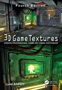
In Figure 2.6 you can see the Layers Window as it appears in Photoshop. This is the window that lets you move and manipulate layers and is not the actual image. The stack of layers on the right is an illustration of the concept of layers and doesn’t actually appear in Photoshop that way. What you see in the Photoshop image window, the actual image you are editing, is what the final image will look like, whether it is in layers or flattened.
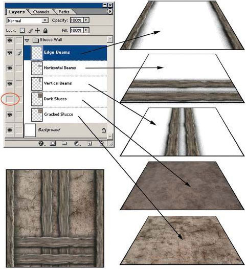
FIG 2.6 At the upper left is the Layers Window as it appears in Photoshop. This tool allows you to move and manipulate layers. The stack of layers on the right is an illustration of the concept of layers and doesn’t actually appear in Photoshop that way.
Flattened means what it sounds like: When all the layers are reduced to one layer, the image becomes one layer—one image. When this happens (if you save your file and thus can’t undo the flatten operation), you lose all flexibility. Notice that in the Layer Window the layer named “Dark Stucco” is turned off (there is no eye icon next to it like the others), so this layer, though actually in the file, is not visible and is not part of the final texture as a result. Also notice that the layer “Horizontal beams” is on top of the layer “Vertical beams,” and these beams have that relationship in the final texture. I output the final texture, which you can see at the lower left of the figure. Layers are critical in texture creation because they allow you to build textures in an easy and effective way and to keep the layers separate so the texture can be adjusted and modified and quickly output again. In Figure 2.7 you can see several examples of how layers are used in Photoshop. Imagine if this layer were flattened and I wanted to remove an element that is part of the final image, such as the horizontal or vertical beams or the cracks. It would be tough: I would essentially have to rebuild the texture instead of clicking a layer on and off.

FIG 2.7 Here you can see two examples of how various textures were built up using layers in one file and, furthermore, how layer control allows for the modification and quick output of a texture.
Now we will speak a bit about working with 2D images that are meant to be used in a 3D space such as a game world. Most game art books talk a lot about image resolution, and that is an important topic, but for now all you need to know is that you are restricted in most games to a certain image size. When you create a 2D image for a game, you will always have parameters, restrictions, and rules that you must follow, and they can range in number from a few to many. Where you are working, what technology you are using, and even what type of game you are making all contribute to determining those specific parameters and guidelines. The most basic and general requirement for game art is that you must make your textures a power of two in size, which means that the images must be a specific number of pixels in height and width. These sizes are typically as follows:
• 16×16
• 32×32
• 64×64
• 128×128
• 256×256
• 512×512
• 1024×1024
• 2048×2048
It is now common to use 2048×2048 maps and much less common to see anything smaller than 256 in most games.
![]() Note
Note
A 512×512 image is four times as large as a 256×256 image, just as a 256×256 image is four times larger than a 128×128 image. Sometimes the fact that the power-of-two numbers are twice as big as the previous number throws some people off. The fact that 256×2=512 makes it seem logical on the surface. But look at Figure 2.8 for a visual representation of this concept. Understanding that concept, you can see that a 512×512 has four times the pixels of a 256×256 image. Not long ago, a 512×512 image was considered a large texture.
We are commonly using 1024×1024 images as a standard size and frequently go up to 2048×2048. Add to that hardware and software advances and the jump in visual quality of a game is simply incredible. This may be even more true for those of us who have watched game technology creep along at first, explode, and then keep growing exponentially. The advances are across the board, and most contribute directly to the visual quality of a game: rag doll physics, more complex and refined animation tools, improved artificial intelligence (AI), more complex yet easier-to-use particle systems—the list is very long.

FIG 2.8 A 512×512 image is four times as large as a 256×256 image, not twice as large. The fact that the number 512 is twice as big as 256 sometimes throws people off. I used an image of some tiles so you can see the relationship. The 256 image overlaid takes up one-fourth of the area of the 512 image.
Back to the power of two and the first question that most people ask: “Why must we make our textures a power of two?” The simplified answer is that most computer game engines and 3D cards require a texture to fit certain criteria because they can process and display them faster. Most game engines do not restrict texture size to a perfect square. Rectangular sizes like 256×512 and 128×1024 are usually acceptable. I started the list of sizes at 16×16, but most game engines today don’t even use textures smaller than 1024 and when they do it is usually for particles and small decals. Plugging in an asset with the wrong parameters can cause an error message, and the asset will be ignored and some engines will even crash. Some engines/game tools might even alter the asset so that it will work, changing size, format, color depth, and so on.
The power-of-two limit actually doesn’t exist in the code of many 3D graphics engines but is still commonly imposed on game developers for various reasons. I believe that you can already use non–power-of-two textures in certain engines, but I would still stick to the grid for most of the work unless I was in an uncommon situation where I needed to use a non–power-of-two texture. Maybe I am biased and simply used to working on the grid, but I believe that it makes building a game easier for everyone involved, from the texture artist to the level designer. That takes us to the next point about the grid: Aside from technical reasons to use the power of two and a grid, there are productivity issues.
So, your images need to be certain pixel dimensions for technical reasons (currently they won’t work in most game engines if they aren’t exact), but it also helps in production to work with these standard sizes. Most major game-world editors (the software tool that you use to build the game world) use a grid system based on the same power-of-two dimensions. If you lay out a hall with a floor that is 256 units wide in the world and place a 256-pixel image on that floor, you are going to get a perfect fit. You can also make the texture 512 pixels and scale the UV mapping down by exactly 50%, and once again, you will get a perfect fit. You can use an image of a tile that is only 128 pixels and UV that cross the floor in a repeating pattern and get a perfect fit, too. This way of measuring makes everyone’s life easier because you are not guessing, eyeballing, and trying to calculate how to make variously sized images fit in odd-sized spaces.
When working in Photoshop, you can use the grid tool to lay a grid over your workspace to subdivide a power-of-two texture into smaller power-of-two units. We will talk about how to do that later in the book, but for now just know that Photoshop allows for the placing of grids and guidelines over your image that are not part of the art but rather are tools that help you keep things straight. For a game developer this functionality is very useful—you just have to remember to set your grid spaces to the power of two. In the commonly used 3D packages like 3ds Max and Maya, you can also set up a custom grid to these dimensions. The result is that the models, textures, and world space are all built on a standard grid, giving the developer consistent units and sizes. A simple example would be the creation of an object for a game decoration, such as a doorway arch. If the texture artist creates a texture for the arch that is 512×1024 and the modeler makes the model of the arch on a grid and creates the arch model 512×1024, the image will fit perfectly over it. I left out the third dimension of depth in the model for this example, to keep things simple. That textured model will then fit perfectly in a 512×1024 doorway that was built on the grid in the game world. Figure 2.9 shows the visual for this example.
Another reason for creating visual elements within a texture on the grid is so that they line up with each other, even if they are on different textures. For example, in many first-person shooters, the height of a stair is 16 units (a power of two). Therefore, if you make a wall texture with a floor molding 16 units high, it will look much neater when the wall molding runs into the stairs. Even though the real world is often put together in a way that defies these guidelines, that is no excuse to allow those mistakes in a game. In a game those are mistakes and they are noticeable and not looked upon as a faithful recreation of reality.

FIG 2.9 A texture created on a grid will fit perfectly on a model created on the same grid, which in turn will fit perfectly into a game world built on the same grid. In this case, the arch model (left) is 512×1024, the texture (middle) is also 512×1024, and the boring doorway (right) that we are trying to fill in the game world is of the same dimensions. You can see all the elements together in the image at the bottom.
In the real world, you will see wallpaper that wasn’t hung correctly, with seams that don’t meet up with each other, or a brick wall that was repaired with bricks that don’t match in color, grass sod that has been laid down in squares by a landscaper and visually tiled, and other messy real-world examples. In Figure 2.10 you can see a simple texture set applied to a game setting; note how all the various textures fit with each other on the various surfaces of the room.
Although some artists view the grid as a limit, others appreciate it as a tool. And given the fact that we are not bound to it nearly as much as we were just a few years ago, it is more of a tool now than a restraint. Working on the grid helps the world stay consistent and look better, and frankly, you can work much faster. This is called modular design. Modular design is very important when you work on a computer game. A computer game requires efficiency and organization. No matter how powerful computers get, you always want to squeeze out every ounce of performance you can. The best way to do that is to use only the textures you need, no more and no less.

FIG 2.10 This texture set of eight textures was built off two base textures: tiles and bricks. Building everything on the grid in Photoshop and 3ds Max allowed for the seamless tiling of the entire set. Notice the pattern that runs through the floor and how it meets at every turn. I was able to rotate the tile with the corner pattern on it and have it still match up to the others. It is pretty easy to tile tiles, I admit, but by making sure they met up properly in Photoshop, I was able to use one corner pattern tile instead of four.
Modular Design
In the context of texture creation, modular design is the art of designing and creating your textures so that they will all fit together. This starts with simple tiling and moves into the next realm of advanced tiling, which we will, of course, cover in Chapter 4, “Prepping for Texture Creation.” In the real world, a great example of modular design is office furniture. You can buy the core desk and add hutches, lighted cabinets, bookcase extensions, and on and on. All these parts are designed to fit together, allowing you to create hundreds of combinations, thus ending up with a desk that is unique and fits your office and your needs. Add to that the ability to swap textures—I mean, select the color and finish you want—and you end up with a huge variety of options.
Earlier you saw an example of texture modularity with the set of textures based on a brick and tile with variations that all fit together. The base brick wall covers most of the surface of the game world. To make that space interesting, I added trim, cracks, a baseboard, a vent, and other details. As we progress, you will become very familiar with the concept of modularity. Modularity extends to all aspects of game design, and 3D modelers often create modular chunks of a game world that can be copied and arranged.
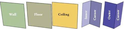
FIG 2.11 These are the basic 3D pieces of geometry for building a modular level.

FIG 2.12 Here the base pieces are assembled into a simple room and hall.
Typically, modelers start with the large common and repetitive chunks such as floor panels, wall panels, ceiling panels, and other repetitive large-world geometry, then move into decorations such as columns, lamps, and special case meshes. They may even create versions of the large modular chunks with damage such as cracks or holes in them. The power of two and the grid are both limits and tools for creating clean, solid levels. In Figure 2.11 you can see the base 3D parts of a simple level set; in Figure 2.12 the parts are assembled into a room and hall; and in Figure 2.13, the room and hall are textured. In Figure 2.14 you can see an additional example of modular design. The castle wall is actually two pieces: one undamaged and one damaged.
As you create textures on a specific project, you will find that in most instances there are many other parameters to consider besides the grid, but these concern the final output file more than the source file. Although the grid must be considered as you build, things like the largest and smallest file size that the engine can handle, the total texture memory you are allotted, and other technical details are pretty much reserved for after the texture is created and pertain to the output file.
As a side note on technical limits, just because there is a maximum texture size a game engine can handle doesn’t mean that you should use a lot of textures at the maximum size. A large image on a small object or one that a player never sees close up is just a waste of resources. In fact, though some game engines demand very specific input parameters, others allow for multiple color depths, variable file sizes and resolutions, and even differing formats. Knowing your engine is important because you can cut file sizes significantly with little to no loss of visual quality simply by knowing what options you have.

FIG 2.13 The simple room and hall, textured.

FIG 2.14 Here is an example of a modular piece of geometry. There are two sections of castle wall; one is undamaged and one has a gaping hole in it. They were built on the grid, so they meet up perfectly. The wall here is several normal wall sections lined up with a damaged section in the middle.
You’ll find that limits will always be imposed on you by development technology, game design, target audience, or even genre. Certain texture size is currently just one of those limits. Most important, knowing those limits and what you can do to work around them makes you more valuable than being just a great artist. If you are able to experiment with file size, compression, color depth, and so on and are able to get twice the number of textures into the game, you will not only free yourself up to do more as an artist—you will also be much more valuable as a developer.
All the textures that you create will end up being mapped onto a 3D object. UV mapping at its simplest is the process of placing a 2D texture on a 3D mesh. We will look at the various ways textures can be placed on a 3D object.
![]() Note
Note
There is a distinction between a texture and a skin. A skin is the art that goes on a more complex model such as a character, monster, or weapon. Skins are generally not tileable and are created for a specific mesh. A texture is generally the art that covers the game-world surfaces: grass, floor tiles, walls, and so on. UVing these surfaces is much simpler than skinning an organic model. You will not be applying your textures to any 3D meshes in this book, but you should understand the various UV mapping types, since they can affect the way you create your textures in some cases.
Mapping Types
Planar Mapping
Planar mapping works like a projector. The texture is projected onto the 3D surface from one direction. This method can be used on walls and other flat planar surfaces, but it is limited and can’t be used on complex objects, since the process of projecting the texture in one direction also creates smearing on the sides of the 3D model that don’t directly face the planar projection. See Figure 2.15 for an illustration of the planar UV mapping type.
Box Mapping
Box mapping projects the texture onto the model from six sides. This method works great on boxes! This mapping scheme can be useful in some varying situations if you plan for it. Obviously you can use it on more complex boxes, and if you design on the grid you can make things work to your benefit. In Figure 2.16 you can see how the box mapping type works in the upper-left corner of the image. At the top right is a rusted box texture and a close-up of the edge of the texture. I made the edge of the box exactly 16 units wide in the texture. Now look at the box model below that. It has an edge that is exactly 16 units wide as well. I can use box mapping here, and the fact that the texture is projected straight through the model causes that 16-unit edge of the texture to map perfectly on all the edges of the outer and inner rims of the box. The lower-right corner has a close-up of the box, and you can see how the highlights and all the edges meet cleanly.

FIG 2.15 Planar mapping projects the texture onto the 3D mesh from one direction. This technique can be used on walls and other flat planar surfaces. However, it is limited and can’t be used on complex objects. Projecting the texture in one direction creates smearing on the sides of a 3D model that don’t face the planar projection directly.

FIG 2.16 Upper left: This is how the box-mapping type works. Top right: A rusted box texture and a close-up of the edge of the texture. The edge of the box in the texture is exactly 16 units wide. The box model below has an edge that is exactly 16 units wide as well.
Spherical Mapping
Spherical mapping surrounds the object and projects the map from all sides in a spherical pattern. You will see where the texture meets along the edge unless you have created a texture that tiles correctly. Furthermore, the texture gets gathered up, or pinched, at the top and bottom of the sphere. Spherical mapping is obviously great for planets and other spherical things. See Figure 2.17.

FIG 2.17 Spherical mapping surrounds the object and projects the map from all sides in a spherical pattern. You will see where the texture meets along the edge unless you have created a texture that tiles correctly. Spherical mapping is great for planets.
Cylindrical Mapping
Cylindrical mapping projects the map by wrapping it around in a cylindrical shape. Seams will show if you have not tiled the texture properly. Cylindrical mapping can be used on tree trunks, columns, and the like. See Figure 2.18 for some examples of cylindrical mapping.
Those are the most basic UV mapping types and are the most common ways that we will apply world textures. Actually, world textures are mostly planar- or box-mapped onto the faces of the world. The process of applying these standard UV mapping types is pretty straightforward and usually automatic in the game editor and can be easily changed by the level builder.
To be successful, a computer game must look good and run well. This is a game artist’s mantra. Until you have tried to accomplish this goal, you have no idea how much at odds these objectives are. Although the primary focus of this book is the generation of art assets for computer game environments, we can’t escape the fact that creating art for a game is more than just making a pretty picture. When you create art for a game, you need to create art that will accomplish several goals, the least of which is that your art must work technically in the game environment and work as efficiently as possible in that environment. This goal requires planning and creating your art to very specific guidelines. Those guidelines may change depending on many variables (I will discuss these later), but they are all essentially the same variables. In any case, you need to be very well aware of what those variables are and build accordingly.

FIG 2.18 Cylindrical mapping projects the map by wrapping it around in a cylindrical shape.
The process of making a game run at its very best is called optimization. It is a common belief that this is solely the domain of the programmer—but nothing could be further from the truth. It is, in fact, everyone’s job to optimize from day one. The artists have a huge impact on how well a game runs, so we need to know every trick possible to achieve this goal. It cannot be stressed enough that you have to be familiar with the most common methods of game-world optimization because much of what can be done to optimize a game is under your control and takes place during asset creation or the implementation of the asset into the world.
There are many things that can or need to be done during the actual assembly of the game world—tasks that might fall to you. Because the computer game must not only look good but also run well, you will have to use every trick available to you. If you don’t, the game world will not run well enough to use or will not look as good as it can. If you fail to make the game look as good as possible due to a lack of optimization, you are wasting an opportunity as valuable as gold in game development.
Game performance is usually expressed as frames per second (fPS). There is a definite limit to what you can do as an artist, programmer, or designer based on fPS—no matter what system specs you are working with. If frame rate is inefficiently used in one place and goes undetected, it is by definition diminishing the available frame rate in other areas of the game. One of my pet peeves is the last-minute gutting of a game to make it run. I have seen entire levels that have taken weeks and months to perfect be gutted at the last minute. Trade-offs are unavoidable, but if you don’t look at your game in its totality and track your frame rate (among other resources), you are going to get caught unaware at the end of development as the game comes together and doesn’t run as you had hoped (Figure 2.19).
Let me repeat (because this drives me absolutely nuts): You have to track your resources. Just because you can run through your level at 120 fPS doesn’t mean that performance is assured. You have to consider several things before celebrating the blistering frame rate: Are you using the target machine, or are you using a high-end machine typical of most development studios? What is left to implement in the game? Are the collision detection and physics in place? What about running AI and game logic? Sometimes the addition of a heads-up display or interface slows things down. As soon as you fire a weapon, you are potentially triggering collision detection, creating hundreds of assets (particles) triggering sound events, displaying decals on walls, and so on. Think about the addition of other players and characters and their weapons. Suddenly you have tens or hundreds of thousands more polygons on the screen, a few more large textures loading, and other assets and events. In short, can you think of every possible thing the final game will have running and guess what your frame rate target should actually be? You probably can’t get a dead-on correct answer early in development, but an educated guess (have lunch with the programmers and question them—they’ll love you for it) and the awareness that your actual frame rate will be cut in half when the game is up and running in full will help you hit a more realistic target and prevent the total destruction of a game level at the last minute.

FIG 2.19 You can’t see it, but is the game engine drawing it and wasting resources?
This section looks at some of the most common tools and techniques accessible to the artist for optimizing a game world. I present them from the artist’s point of view, meaning how the tool or technique works and what control the artist generally has over it. Usually you will see that most of these tools and techniques are explored or presented from the programmer’s point of view (they are very involved programmatically, to put it mildly), but artists really need to understand these devices, since they are critical to making a level look good and run well.
I personally break optimization into three major areas: asset based, collision based, and occlusion based. In this book we will look only at the asset-based optimizations, because they are in the domain of the texture artist. The other two take place in the modeling and world-building phases. Aside from the things we as artists can do to optimize the game, there are of course many other areas that also need to be optimized. Most of these optimizations are found in the program code. Things like memory management, central processing unit (CPU) and graphics processing unit (GPU) code, AI, collision code, networking, sound, and the game play itself all eat up resources and need to be optimized by the programmers.
Asset-based optimizations are simply those optimizations that you can implement and affect during asset production. Assets are the art we create, and they present the first opportunity that we have to apply any optimizations. Technically, there are always opportunities from day one to keep optimizations in mind and apply them during the design phase, but often the artist is not present during this time. Our first opportunity is usually when we start to create the assets for the game. Some optimizations are possible in the design and planning of the assets; for example, the design of how a texture is laid out affects the way the UV maps are laid out, and that in turn can affect performance.
![]() Note
Note
The artist is responsible for a great deal of the optimization in a game. In every phase, from planning to creating to introducing those assets into the game world, there are opportunities to optimize.
The most common asset-based optimizations are as follows:
• MIP mapping
• Texture pages
• Unlit textures
• Multiple UV channels
• Lightmaps
• Masking and transparency
• Texture size and compression
MIP Mapping
MIP mapping, sometimes called texture level of detail (LOD), is usually a programmer-controlled function, but sometimes the artist is given control of this function, too. MIP stands for the Latin phrase multum in parvo, which means “many things in a small place.” The explanation is pretty simple: A large texture seen at a far distance in a game world looks the same as a smaller texture due to the fact that both are being displayed using the same number of pixels on screen; it is therefore a waste of resources to use a large texture on an object that is far away in the game world. In addition, using a larger texture on a small, faraway object usually doesn’t look as good as the smaller texture would, due to the fact that the larger texture is being resized on the fly by the game engine. To solve both these problems, programmers usually implement some form of MIP mapping.
MIP mapping is the creation of multiple sizes of a texture for display at various distances in the game (Figure 2.20). Sometimes you can see the MIP maps pop as they change from larger to smaller, especially in older games. MIP mapping allows the texture to be viewed close up and in detail as well as render faster (and look better) from a distance. Figure 2.21 shows the MIP-mapped texture of some jungle vines. Notice that the alpha channel is MIP mapped as well. Fortunately, NVIDIA created several tools to make all this easier for the artist (Figure 2.22). The DXT Compression Plug-in is one of the most useful tools, and I discuss that later in this chapter in the section on texture size and compression. With this tool you can control many variables that affect the visual quality of the image.
![]() Note
Note
Texture LOD and LOD pertaining to a 3D model in the game engine are both the same concept, but one applies to the use of gradually smaller 2D assets and the other applies to 3D.

FIG 2.20 Textures that have MIP maps associated with them. (Sample images from Glory of the Roman Empire, courtesy of Haemimont Games.)

FIG 2.21 Textures that have MIP maps associated with them and an alpha channel. Notice that the alpha channels are MIP mapped as well. (Sample images from Glory of the Roman Empire, courtesy of Haemimont Games.)

FIG 2.22 This figure shows the interface and examples of the NVIDIA MIP-mapping tool.
Texture Pages (or T-Pages, Atlas Textures, or Texture Packing)
This section starts with a bit of a disclaimer: It seems that the industry is now moving away from texture atlases. Although atlases will continue to be an effective solution for some hardware, things are shifting over (due to technical reasons that are beyond me) to individual textures. That’s great news for me—I find that texture atlases slow things down in the typical artist’s workflow. But on the other hand, the explosion of apps for mobile devices are requiring the use of texture atlases once again.
As you build a game world, you create many textures to cover the many 3D objects in the world. When the game world is loaded and run in the game engine, the game engine has to access (call) each of those textures for each frame it renders. These calls slow everything down, so it is desirable to reduce the number of calls. You can use a technique called texture packing, which is creating a texture atlas, that can accomplish this task. Basically, texture packing involves taking a large group of textures that are related in some way (usually geographically close to one another in the game world) and putting them together to create one large texture. You can see a texture atlas of foliage created for a jungle level in Figure 2.23. You can create an atlas by hand or with a tool. Of course, NVIDIA makes such a tool (Figure 2.24). The primary benefit of a tool like this for the artist is the speed at which atlases can be built and altered. This tool creates the one large texture and with it a file that tells the game engine where each image is placed on the master image.

FIG 2.23 An example of an atlas texture.
Unlit Textures
An unlit texture is a texture that is unaffected by lighting and displays at 100% brightness—sometimes called a full bright or self-illuminated texture. Note that this not the same as a texture that uses an illumination map. When an illumination map is used, it must calculate lighting for a texture and take into account the grayscale illumination map. Because calculating the lighting for a texture can be one of the biggest resource hogs in a game, it can be much more practical to use an unlit texture, which renders much faster.
Using unlit textures is a way to boost performance. This technique is easy with some materials such as water or certain signs, and in some game types or genres you can get away with using large numbers of unlit textures. Large forested outdoor areas can benefit from the use of unlit textures on the foliage. Figure 2.25 shows an example of a texture that is lit in one scene and then unlit in the next. Notice how the sign is at full brightness and remains unchanged by the lighting affecting the walls. Particle systems typically look better unlit and run faster as well (Figure 2.26).
Multitexturing or Multiple UV Channels
Increasingly often in today’s game engines you are not limited to one UV channel. Thus you are allowed to combine textures on a surface in real time. That in turn allows a great degree of variety from a relatively small set of assets. A grayscale image may simply define the dark and light areas of a surface, another map may define color, and another some unique detail. You can see an example of this method in Figure 2.27. The building mesh has a base-colored material applied; on a separate channel I applied dirt, and on another I added details such as posters and cracks. Multiple UV channels are also used to apply bump mapping and other shader effects.

FIG 2.24 The texture atlas and accompanying index file.
Lightmaps
Lightmaps are prerendered images that define the light and shadow on the surfaces of your world. Lightmaps are created before the game runs and are saved as part of a file, which means that the size of that file is increased. There are two things you can do to optimize lightmaps: Lower their resolution or compress them. A smaller lightmap will result in a faster loading and running level, but lowering the resolution also lowers the quality (Figure 2.28).
FIG 2.25 An example of a texture that is lit in one scene and unlit in the next.

FIG 2.26 Particles, lit and unlit.

FIG 2.27 Multitexturing allows you to combine a relatively small set of assets in creating a large variety of surfaces.
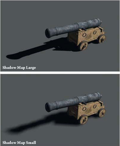
FIG 2.28 Lightmaps, both large and small, on the same area.
![]() Note
Note
For a great article on compressing lightmaps, go to http://Gamasutra.com and look up “Making Quality Game Textures,” by Riccard Linde.
Usually you can opt out of using a lightmap or can determine at what size the lightmap will be created. This step allows you to increase the resolution of the lightmap in those areas where the player can go and lower the resolution for less accessible but visible areas.
Masking and Transparency
When possible, it is preferable to use masking instead of transparency because masking renders more quickly. Take a look at Figure 2.29, since these concepts are much easier to grasp pictorially.
Masking typically uses a specific color that is designated the “clear” color, and this creates hard, jagged edges (although newer hardware can handle largerresolution textures and can post-process the images and smooth the edges).
Transparency uses a separate additional channel, a grayscale image called the alpha channel, to determine the opacity of a pixel. The trade-off is that transparency looks better than masking, but it also requires more file space and more processing power. This is because although masking simply either draws the pixel or not, transparency must look at two pixels (the source image pixel and the on-screen pixel behind it), consider the grayscale pixel of the alpha channel, and calculate the color of the final on-screen pixel.

FIG 2.29 This is the way the two methods discussed here work with examples.

FIG 2.30 The interface and various windows of the NVIDIA tool as applied to masking and alpha.
Technically, what you are seeing isn’t real-world transparency but rather a new image composed of a blending of two images that gives the illusion of transparency.
Of course, NVIDIA makes a tool that allows for the rapid adjusting and viewing of textures before outputting them (Figure 2.30).
Texture Size and Compression
Make sure to consider the size of each texture you create. A texture that covers most of the walls and/or floors in your world and has to tile well while still holding up visually needs to be larger than a texture that is displayed infrequently and is not subject to the player’s direct examination. The other factor is compression. A compressed texture file can be significantly smaller than an uncompressed one yet still maintain visual integrity using the right combination of compression options. NVIDIA makes a plug-in (http://developer.nvidia.com) for Photoshop that allows for the rapid and easy iteration through many compression schemes before final output of the file (Figure 2.31).
Remember that there are many factors to consider in determining texture size and compression. How close will the player get to the asset? How often will the asset appear in the world, and how many times is it expected to tile or repeat? Can you achieve the same effect with a more efficient solution? Can you use three small textures on multiple UV channels as opposed to one enormous texture? How much can you compress or reduce the resolution of an image and still maintain visual integrity? One of the most valuable but underappreciated skills a game artist can acquire is knowing not only the various ways of implementing game art solutions but what methods and combination of those methods comprise the best solution.

FIG 2.31 The interface and various windows of the NVIDIA tool as applied to the compression options.
This chapter presented a quick overview of some vast and complex topics. But the level of coverage of these concepts is enough to help you create textures that will work in a game world. Learning and mastering any one these concepts will take time, but fear not: good, basic knowledge will allow you to work up to mastering these topics more quickly and more easily.
1. Photoshop, with all its powerful tools and options, simply gives you an almost unlimited number of ways to do what?
2. Why is working on the grid useful?
3. Explain the difference between a source and an output file.
4. What are the four criteria for choosing a graphic file format?
5. What are the DDS and DXT formats? Explain the features and options of these formats.
6. What is the PSD format? List and define at least three features of a PSD file.
7. What is the grid? Explain.
8. A 512×512 image is how many times as large as a 256×256 image? Explain your answer.
9. What is modular design?
10. What is UV mapping? List and define the most common UV mapping types.
11. What is the mantra of a computer game artist?
12. What is optimization and why is it important?
13. Why is it important to track the performance of your game as a whole entity?
14. What are the seven optimizations examined in this book and how do they speed things up?