12
Building a Data Model
The previous chapter described requirements gathering for the Pampered Pet database project. It took the basic requirements and used them to build the fundamental entities that will take part in the database's operations.
This chapter builds more formal data models describing those entities. Semantic object models emphasize the entities' fields, and entity-relationship diagrams emphasize the relationships among them.
In this chapter, you'll see examples of:
- Converting requirements entities into semantic objects
- Splitting off repeated data into new objects
- Converting requirements entities and semantic objects into entity-relationship diagrams
- Converting semantic object models and entity-relationship diagrams into relational models
SEMANTIC OBJECT MODELING
Semantic object models have the advantage that they are relatively close in structure to the kinds of entity definitions that you typically get out of requirements gathering. They focus on the attributes that objects have. That is the same type of information that you get by studying the customer's needs and user interface mockups, and then figuring out where those mockups will get their data.
Building an Initial Semantic Object Model
To build a semantic object model, review the tables showing data integrity needs that were presented in the section “Determining Data Integrity Needs” in Chapter 11, “Defining User Needs and Requirements.” The chapter's text showed the data needed by the Order and InventoryItem entities. The exercises built tables showing the data needed by the Course, Employee, Shift, Customer, TimeEntry, and Vendor entities. Chapter 11 also discussed the relationships among those entities.
To convert the data requirements tables in Chapter 11 into semantic objects, simply convert the entity's pieces of data into attributes. Then add object attributes to represent relationships with other object classes.
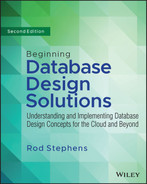
For example, the following table summarizes the Course entity's fields given in Chapter 11.
| FIELD | REQUIRED? | DATA TYPE | DOMAIN |
|---|---|---|---|
| Title | Yes | String | Any string |
| Description | Yes | String | Any string |
| MaximumParticipants | Yes | Integer | Greater than 0 |
| Price | Yes | Currency | Greater than 0 |
| AnimalType | Yes | String | One of: Cat, Dog, Bird, and so on |
| Dates | Yes | Dates | List of dates |
| Time | Yes | Time | Between 8 a.m. and 11 p.m. |
| Location | Yes | String | One of: Room 1, Room 2, yard, arena, and so on |
| Trainer | No | Reference | The Employee teaching the course |
| Students | No | Reference | Customers table |
One non-obvious detail is that Dates values should be after the current date when you create a new Course entity. It doesn't make sense to schedule a new Course in the past (unless you're training Temporal Terriers or Retrodoodles). After you create the Course, however, the record will continue to exist, so you can't make this a database constraint. Instead, the user interface should verify the date when you create or reschedule a Course.
The Course entity has two relationships, one to the employee teaching the course (Trainer) and a second to the customers taking the course (Students). Figure 12.1 shows the corresponding semantic object class.
Improving the Semantic Object Model
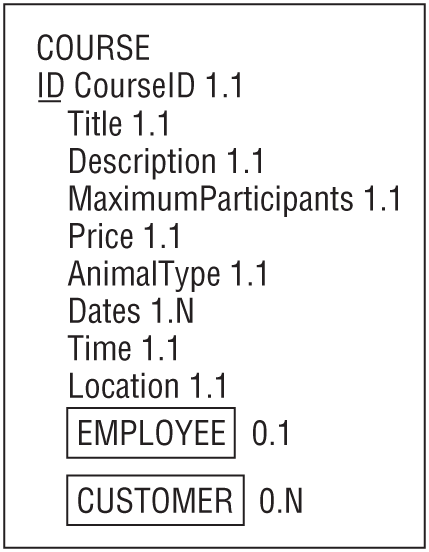
Figure 12.3 shows a first attempt at building a semantic object model for the major entities identified so far.
Notice that the relationships in Figure 12.3 are two-way. If object A is related to object B, then object B is related to object A. For example, in this model the EMPLOYEE class contains an object attribute referring to COURSE and the COURSE class contains an object attribute referring to EMPLOYEE.
A quick look at Figure 12.3 uncovers several problems. First, the ORDER class contains two addresses: the customer's address and a shipping address. They are the same kind of data, so they should be represented by a repeating multivalued attribute.
This model doesn't acknowledge the relationship between orders and customers. A customer places an order, but there's no link between the ORDER and CUSTOMER classes. The model should be changed to make that relationship explicit.
Furthermore, one of the addresses contained in the ORDER class is actually the customer's address. That address is already represented in the CUSTOMER class, so it's not needed in ORDER.
The ORDER class's second address is the shipping address. It probably makes sense to leave that address in the ORDER class rather than moving it into CUSTOMER because it tells where that particular order should be shipped. If this address is missing, the order should be shipped to the customer's address.
Because ORDER and CUSTOMER both contain addresses, it makes sense to create a new ADDRESS class to hold address data for both of those classes.
Figure 12.3 also shows that the CUSTOMER, EMPLOYEE, and VENDOR classes share several attributes in common. They all include name, address, email, and phone information, which makes intuitive sense because customers, employees, and vendors are all types of people.
To recognize the relationship among customers, employees, and vendors, it makes sense to build a PERSON parent class that holds name, address, email, and phone information. The CUSTOMER, EMPLOYEE, and VENDOR classes then become subclasses of the PERSON class.
Finally, the phone information in the CUSTOMER, EMPLOYEE, and VENDOR classes is not exactly identical. The CUSTOMER and EMPLOYEE classes include both home and cell numbers, whereas the VENDOR class has only a single contact phone number. That makes sense (most vendors don't want you calling their employees at home), but it's easy to generalize the model slightly and allow the PERSON class to hold any number of phone numbers of various kinds. A VENDOR object may never need a home phone number, but it doesn't hurt to allow the possibility.
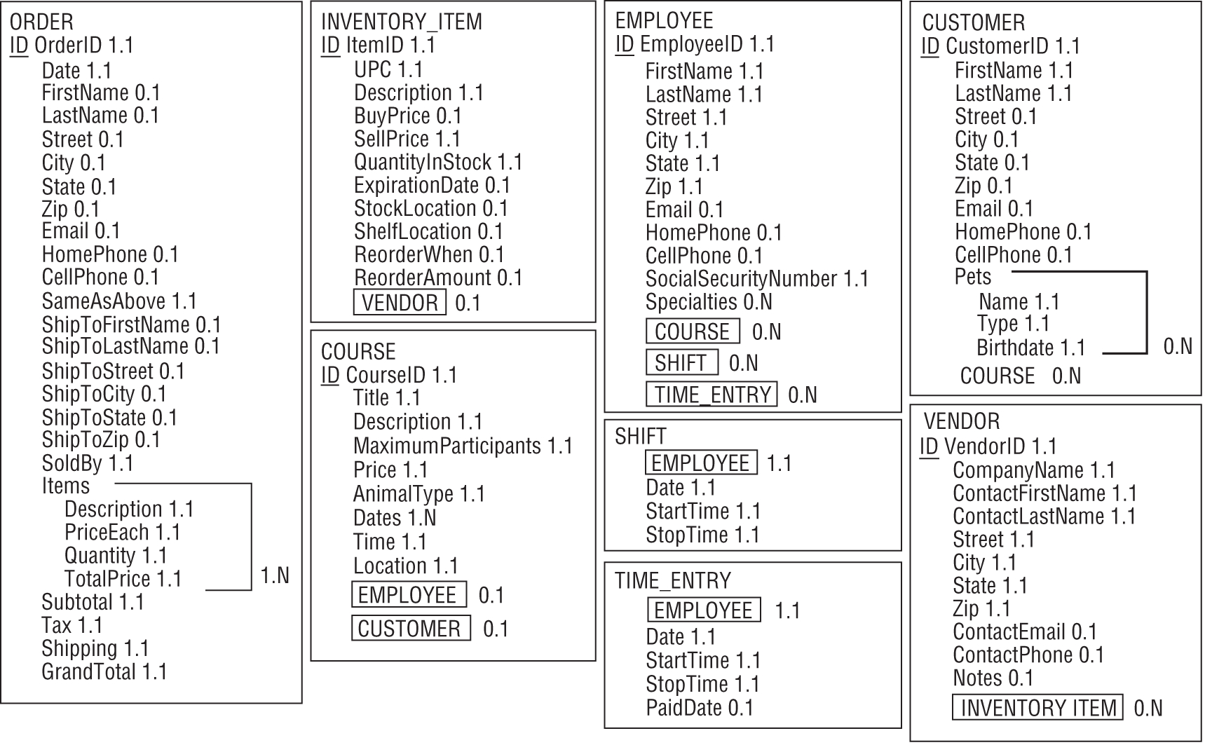
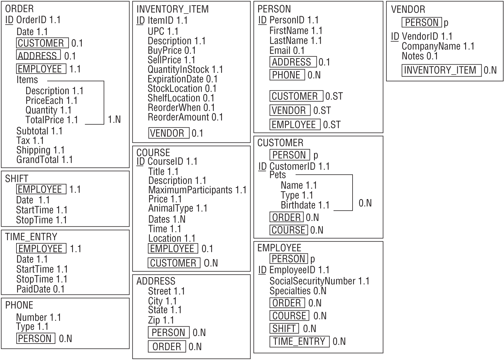
Figure 12.4 shows the improved model.
Note that some of these steps used to improve the model actually make the database more normalized. Many people think of normalization as a step that occurs after the data model is complete, but it really occurs throughout the data modeling process. As you see parts of the database that need to be normalized (and with experience you'll see them earlier and earlier), go ahead and fix them even if the model isn't complete yet.
ENTITY-RELATIONSHIP MODELING
Though semantic object models are fairly easy to build from lists of the database's main objects and their properties, they have the disadvantage that their structure doesn't closely match that of a relational database. Although the objects typically map into relational tables, the semantic object model doesn't emphasize the relationships among the entities. It also allows data arrangements that don't fit the relational model, such as attributes that are repeated any number of times within the same entity.
An entity-relationship model has a structure that's closer to the one used by relational databases, so it makes some sense to convert the semantic object model into a set of ER diagrams.
Building an ER Diagram
To start converting the semantic object model into ER diagrams, consider a particular semantic class and build a corresponding entity set. Connect it to other entity sets representing the class's object attributes.
Finally, consider the class's group attributes. If a group attribute is repeated, you should probably move it into a new entity connected to the original one. If a group attribute occurs only once, you might still think about moving the data into a new entity to either allow repetition later or to make similar data uniform across other entities. If a STUDENT class contains a single Address group attribute, it might be worth moving the Address data into a new table that holds address data for all kinds of entities (Instructor, Employee, and so forth).
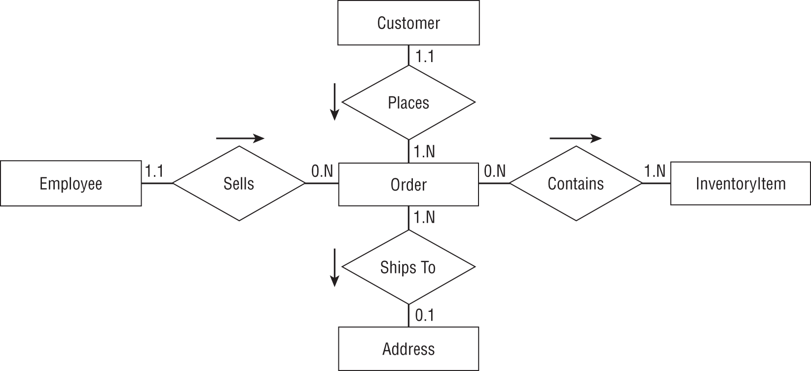
For example, the ORDER class shown in Figure 12.4 is one of the more complicated classes, having relationships with three other classes: CUSTOMER, ADDRESS, and EMPLOYEE. To start building the ER diagram, you would create an Order entity set and connect it to Customer, Address, and Employee sets.
The ORDER class has one repeating group attribute: Items. Move that data into a new InventoryItem entity set and connect it to the Order entity.
For each of the relationships, think about how many of each type of entity could be associated with a single instance of the other entity type. For example, the Order entity is related to the Customer entity. A single Order must have exactly one Customer, so the Customer end of the relationship gets cardinality 1.1. Looking at the relationship from the other end, a single Customer might have 1 or more Orders, so the Order end of the relationship gets cardinality 1.N.
Similarly, you can find the cardinalities for the Order/Employee, Order/Address, and Order/InventoryItem relationships.
Figure 12.5 shows the ER diagram for the Order entity and its relationships.
Building a Combined ER Diagram
After you build separate ER diagrams for each of the classes defined by the semantic object model, you can combine them into one big diagram. The individual diagrams are enough to let you understand the entities' relationships on a local level, but a combined diagram can help show larger patterns of relationship.
Sometimes, it can be tricky arranging the entities so their relationships don't overlap and are easy to read. In that case, it is sometimes useful to leave parts of the model out and show them in separate diagrams.
Figure 12.7 shows the combined ER diagram for the bottom-level classes modeled in Figure 12.4. To keep things a bit simpler, the diagram displays the Customer, Employee, and Vendor entities but does not show the fact that they are subclasses of the Person parent class.
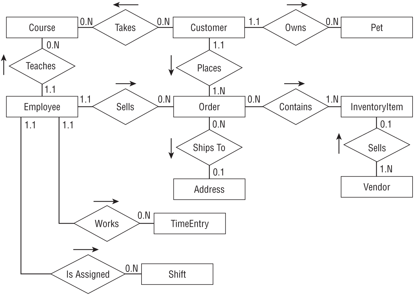
The diagram shown in Figure 12.7 uses more descriptive and business-oriented terms wherever possible. For example, from a purely theoretical perspective, you could say that an Employee “has a” Shift, “has a” TimeEntry, and “has a” Course. That would be more uniform but would make the diagram much harder to read.
Figure 12.8 shows the inheritance hierarchy containing the Person, Customer, Employee, and Vendor classes. You could squeeze this onto the diagram shown in Figure 12.7, but it would make the result more complicated. (I think this part of the model is easier to understand in two pieces.)
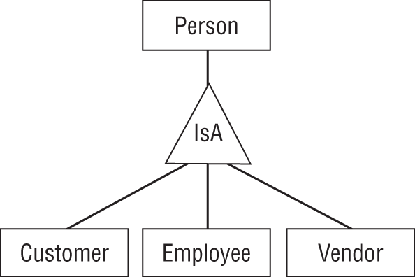
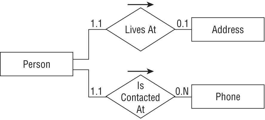
Figure 12.9 shows the entities representing the last remaining classes shown in Figure 12.4. This figure shows the relationship between the Person parent class and the Address and Phone entities. (You could easily add this to Figure 12.8 but to me the two seem logically separate. One shows inheritance and the other shows entity relationships.)
Improving the Entity-Relationship Diagram
If you look closely at Figure 12.7, you'll find two many-to-many relationships. First, a Customer may take many Courses while a Course may have many Customers enrolled. Second, an Order might contain many InventoryItems and an InventoryItem can be part of many Orders.
Entity-relationship diagrams have no trouble modeling many-to-many relationships, but a relational model cannot. To see why not, consider the relationship between Customer and Course. To build this relationship in a relational model, one of the tables must contain information linking it to the other.
To link a single Customer record to many Course records, you would need to list many Course IDs in the Customer record. Because a customer might take any number of courses, that would require the Customer record to contain an indefinite number of fields, and that's not allowed in a relational model.
Now suppose you try to make a single Course record hold information linking it to several Customer records. That would require the Course record to contain an indefinite number of fields, and that's not allowed in a relational model.
The way out of this dilemma is to create an intermediate entity to represent the combination of a particular customer and a particular course. Then you can connect the Customer and Course entities to the new one with one-to-many relationships, which can be represented in a relational model.
Figure 12.10 shows this new piece of the entity-relationship puzzle. Now a Customer is associated with any number of CustomerCourse entities, each of which is associated with a single Course. Similarly, a Course is associated with any number of CustomerCourse entities, each of which is associated with a single Customer.
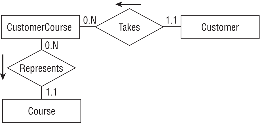
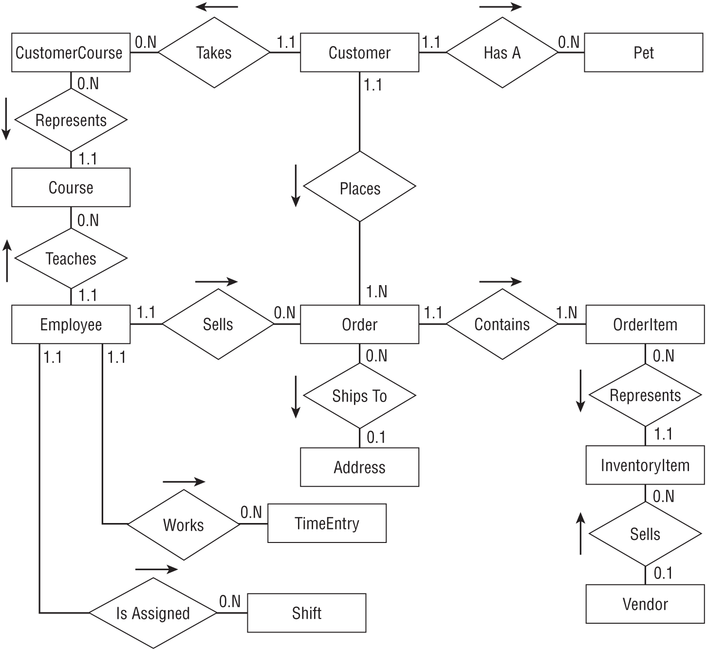
Figure 12.12 shows the new larger ER diagram from Figure 12.7 with the many-to-many relationships replaced by intermediate tables.
The changes to remove the many-to-many relationships are another step that normalizes part of the database. They remove the need for repeated columns in tables by replacing them with intermediate tables. The entity-relationship model can represent many-to-many relationships, so you don't really need to remove them at this stage. Instead, you could wait and remove them when you build the relational model in the next step. However, the diagram shown in Figure 12.7 makes these relationships easy to see, so this is a reasonable time to straighten them out, and it will make building the relational model easier in the following chapters.
RELATIONAL MODELING
The semantic object model made it easy to study the classes that will make up the database and allowed some normalization. The entity-relationship model emphasized the entities' relationships and made it easy to remove many-to-many associations.
Now it's time to use what you've learned by building the semantic object and entity-relationship models to create a relational model.
Start by making a table for each of the models' classes and entity sets. Look at the final ER diagrams shown in Figures 12.8, 12.9, and 12.12, and make tables for the entities drawn in rectangles. The following list shows the tables that you need to create:
- CustomerCourses
- Customers
- Pets
- Courses
- Employees
- Orders
- OrderItems
- Addresses
- InventoryItems
- TimeEntries
- Shifts
- Vendors
- Persons
- Phones
Refer to the semantic object model in Figure 12.4 to find the basic fields that each table needs.
Next, consider the tables that are directly related in the ER diagrams. Figure 12.12 contains several one-to-many relationships. To implement those in the relational model, you need one of the related tables to include a field that leads back to a field in the other table. The table at the “one” end of the one-to-many relationship cannot hold an unknown number of fields linking to the “many” records, so the fields must work the other way around.
In the table on the “one” side of the relationships, identify the primary key fields. Remember, to qualify as a primary key, the fields must guarantee uniqueness so that no two records in the table can have exactly the same primary key values.
Because those fields will be used as the record's primary key, they should not be values that you will want to modify later. For example, a combined FirstName/LastName key is a bit risky because people do occasionally change their names.
The key values will also be contained in the table on the “many” side of the relationship, so it's better if the key doesn't include a lot of data. The FirstName/LastName pair might be a moderately long text string. Though it won't hurt database performance too much if you use such a key, it's easier to work with a single field key.
If the table on the “one” side of the relationship doesn't contain an easy-to-use natural key, add one. Name it after the table and add “Id” at the end.
For example, consider the relationship between the Address and Order entities. Figure 12.12 shows that this is a one-to-many relationship with the Address entity on the “one” side. That entity contains Street, City, State, and Zip attributes. Even if you allow only a single customer per street address, using those fields as the primary key would be risky because you might need to change them later. For example, an employee might misspell the customer's street name when creating the customer's record. Even worse, a customer might move to a new address. In both of those cases, it would be seriously annoying to have to delete the customer's record and create a new one just to update the address. (I once had an Internet service provider that couldn't seem to figure out how to change a customer's email address without closing the account and opening a new one. I'd send them a copy of this book if I thought they'd read it.)
Because this table has no natural primary key, add an AddressId field to it and use that to link the tables together.
Now add an AddressId field to the “many” side of the relationship. In this example, that means adding a new field to the Orders table.
Finally, draw the link between the two tables, place a 1 next to the “one” end of the relationship, and add a ∞ next to the “many” end.
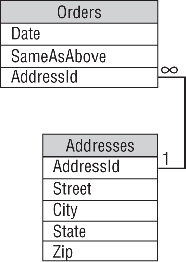
Figure 12.13 shows the resulting relational model for these two tables. Note that this version considers only those two tables. In the more complete model, these tables will need additional ID fields to link them to other tables.
PUTTING IT ALL TOGETHER
Continue examining the relationships shown in the ER diagram in Figure 12.12. Find or create a primary key in the table on the “one” side of the relationship and add a corresponding field in the table on the “many” side.
You can make arranging the tables easier if you place them in roughly the same arrangement that the corresponding entities occupied in the entity-relationship diagram. (Figures 12.13 and 12.14 show the Addresses table below the Orders table because the Address entity is below the Order entity in Figure 12.12.)
You'll probably need to move the tables around a little because they won't be the same size as the rectangles in the ER diagram, but starting with that arrangement should make drawing relationships between the tables easier.
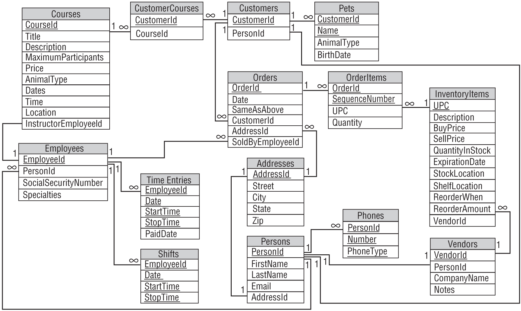
Figure 12.15 shows the resulting relational model.
As a quick check, examine each relational link. The end touching a primary key field should have cardinality 1. The field's name should be the table's name plus “Id.” The exception to this naming convention is in the InventoryItems table, which uses the natural primary key field UPC.
The end of a link touching the foreign key field on the “many” side of the relationship should have the same name as the ID field and should have cardinality 1 (for a one-to-one relationship) or ∞ (for a one-to-many relationship).
Notice that the two intermediate tables used to represent many-to-many relationships, CustomerCourses and OrderItems, contain little more than keys linking to the two tables that they connect. For example, the CustomerCourses table contains only a CustomerId field linking to the Customers table and a CourseId field linking to the Courses table.
The OrderItems table includes its two linking ID fields plus the SequenceNumber field to make the primary key unique and to allow sorting. It also contains a Quantity field to indicate the number of that type of item included in the order (for example, 12 scratch posts).
SUMMARY
This chapter explains the data modeling steps for the Pampered Pet database project. It showed how to build a semantic object model and how to convert that into an entity-relationship model. Along the way, it showed how to improve the models by normalizing parts of them.
In this chapter, you saw examples of:
- Building semantic objects
- Moving repeated semantic group attributes and some other group attributes into new classes
- Converting a semantic object model into an entity-relationship model
- Representing a many-to-many relationship with two one-to-many relationships
- Improving models by normalizing parts of them
- Converting semantic object models and ER diagrams into a relational model
- Adding ID fields to tables
- Converting entity relationships into relational links
Not all projects use both semantic object models and entity-relationship models. Many developers prefer one or the other and don't bother with the extra work of creating two models. Some even jump straight to a relational model. Each of these types of models has its strengths and weaknesses, however, so it's often useful to work through all three kinds.
Figure 12.15 shows a pretty reasonable relational model for the Pampered Pet database, but it's still not perfect. If you look closely, you might be able to identify a few places where the tables are not well normalized. (Can you spot the tables that are not even in first normal form?)
Chapter 13, “Extracting Business Rules,” shows how to improve the model by isolating business rules that are likely to change in the future. Chapter 14, “Normalizing and Refining,” further normalizes the database and puts the finishing touches on it.
Before you move on to Chapter 13, however, use the following exercises to test your understanding of the material covered in this chapter. You can find the solutions to these exercises in Appendix A.