CHAPTER 3
DRAWING WITH FLASH'S VECTOR TOOLS
Now that you have familiarized yourself with the "kitchen," it is time to start opening up a few drawers and taking a look at the tools you will have at your disposal to cook up the necessary ingredients to dish up some Flash.
From the simplest of Flash advertisements to the most exquisite of all Flash applications, all have two things in common: graphics and colors. Here you will get familiar with the basic tools to create vector graphics, apply colors, and add a little extra flavor to your creations by spicing things up a bit.
Understanding graphic types
One of the driving themes throughout this book is Flash's ability to work with many different types of data and media. Graphic elements are certainly no exception to this theme. In order to make the best decisions about what types of graphics to use in your Flash projects, it is important to understand the two primary types of graphics and their pros and cons. Understanding these basic fundamentals will translate into better-looking applications and smaller file sizes.
By default, Flash is a program designed to animate vector images. However, it is possible to effectively integrate various types of bitmap graphics to enhance the user's experience as well. Before we get started, you need to understand the difference between bitmap and vector images.
Bitmap graphics
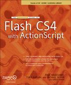
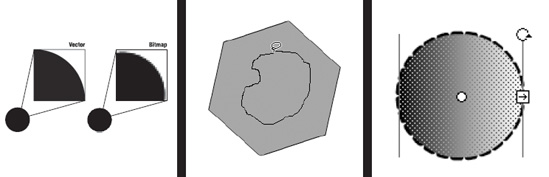
Bitmap graphics are made up of tiny dots or pixels (px). Each pixel is assigned a color value and coordinate that represents its placement within the image. You can think of bitmaps as mosaics that use many different colored pebbles to create a larger image. Because of the fine detail that can be achieved using this method, bitmap graphics work best for photos and artwork with a lot of colors and/or gradients. The disadvantages of bitmap graphics are file size, editing, and scalability. Bitmap graphics typically have a larger file size than vector graphics. Figure 3-1 shows an example of a bitmap image and the negative side effect of scaling this type of graphic.
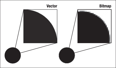
Figure 3-1. The difference in scaling vector and bitmap images. The vector image will maintain its smooth edge, while the bitmap becomes jagged.
Vector graphics
Vector graphics are defined by points. These two points are used to create a line, which is also called a vector, hence the term "vector graphic." Vectors are also commonly referred to as line segments. The points that define a line segment are also responsible for determining whether that line is curved or straight. One or more segments joined together make up a path. Multiple segments and paths can be joined together to create shapes.
To understand the initial advantage of vector graphics, picture a 100 × 100 px square. If this square were a bitmap graphic, we would have a total of 10,000 px (100 by 100), each defining a color, coordinate, and alpha value (transparency). If the square were a vector graphic, each corner of our square would be defined by a point. These points would subsequently be connected, forming segments (vectors). Therefore, our picture would be defined by a total of 4 points, as opposed to 10,000. Further, if we increased our picture to a size of 200 × 200 px, our total would be increased to 40,000 px. Our vector image, however, would still be constructed with 4 points. This as you can see lends itself to a considerable file size difference.
Figure 3-1, shown previously, demonstrates the effects of scaling on both a vector and bitmap image. As you can see, vector images allow for a greater degree of scalability.
Working with vector graphics
In Adobe Flash CS4 a number of different tools are available to you for creating vector graphics. Here you will learn what those tools are and what each one of them does. It is important to gain familiarity and become comfortable with using these tools. As you learned in Chapter 1, Flash is first a vector-based drawing tool, and you will be using this tool for most of your Flash projects.
Drawing modes: Merge Drawing vs. Object Drawing
Before we begin you have to understand a little bit about how Flash handles vector graphics on the stage. There are two drawing modes used in Flash: Merge Drawing and Object Drawing.If you are a veteran Flash user, the first is probably all too familiar to you. The second, though not a new feature in CS4, was introduced in Flash 8 and is often overlooked.
Merge Drawing
Merge Drawing is how drawing in Flash has been handled since its early years. This mode gets its name from its behavior of overlapping shapes. If you come from other design programs such as Adobe Illustrator or Adobe Photoshop, you are aware of the concept of arrangement, where each vector element on the stage is either in front of or behind other elements on the stage. In Flash, when in Merge Drawing mode, there is no concept of arrangement on a single layer. All shapes on the stage occupy the same plane of existence.
So what happens when two shapes overlap? For shapes of the same color, the shapes will merge together as one shape. For shapes of different colors, the selected shape wins dominance and "knocks out" its shape in the shape it is overlapping as shown in Figure 3-2. This was a common frustration among Flash designers, who would oftentimes inadvertently merge shapes together or knock out portions of other shapes by dropping them on top of each other. To avoid this, designers would draw a shape and then group it. Grouped objects in Flash behave as separate objects and introduce the more familiar concept of arrangement. Obviously somebody was listening to the Flash community and introduced the second drawing mode to compensate for this: Object Drawing.
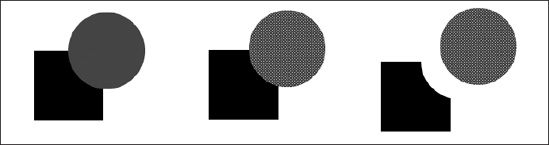
Figure 3-2. In Merge Drawing mode, overlapping shapes will knock out one another.
Object Drawing
When Adobe purchased Flash in 2005, it wanted its principal programs to have an integrated feel. One of the first enhancements that was discussed was the concept of Object Drawing. Because so many of the graphic elements that were used in Flash were created in both Illustrator and Photoshop, Adobe wanted to capture some degree of cross-software familiarity. Object Drawing was Adobe's answer to Flash designers the world over.
When drawing in Object Drawing mode, shapes are automatically grouped and treated as individual objects called Drawing Objects. Drawing Objects occupy space on their own plane of existence. This means that overlapping shapes have no effect on each other. The overlapping portions are simply hidden from view by the object in front of it as shown in Figure 3-3.
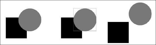
Figure 3-3. Object overlapping
By default, Flash is in Merge Drawing mode. To change drawing modes, click the Object Drawing button that appears at the bottom of the Tools panel as shown in Figure 3-4. You can also easily access this feature by pressing the J key when you have a drawing tool selected.
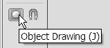
Figure 3-4. Object Drawing button located at the bottom of the Tools panel
Creating and manipulating lines
Lines are the simplest forms in design and the basic building blocks of shapes. To create lines in Flash, you can use the Line tool and the Pencil tool. A line in Flash is nothing more than a segment, or vector, that can have color applied to it.
The Pen tool is another tool that can be used to create lines, as well as complex paths and shapes; we will cover this tool in the section "Advanced drawing," which comes later in this chapter.
The Line tool
The Line tool is used for creating straight line segments. To draw a line using the Line tool, select the Line tool from the Tools panel. You should see your mouse cursor turn into a set of crosshairs. Now click the stage and drag the mouse with your mouse button still pressed. You will see the length and angle of the line change as you move your mouse around. As you can see, you can create a line of any length and at any angle. To set the line, simply release the mouse button.
Now, you may or may not have tried to draw a horizontal or vertical line. If you did, you may have noticed it required a fairly steady hand. To make things easier, you can hold down the Shift key to constrain a line's angle at 45-degree increments. Draw another line, but this time draw it at a 45-degree angle.
Again, select the Line tool if it isn't already selected and click the stage. Now hold down the Shift key and drag the cursor down and away. You may notice as you are dragging that the line will jump back and forth between horizontal, vertical, and 45-degree angles. Release the mouse button to set the line.
The Shift key is known as a modifier key because you can use it to change the behavior of a tool. In general the Shift key and the Alt key (Option on the Mac) are used as modifier keys for a lot of the drawing tools in Flash. The Alt key switches the point of origin to the center of the shape you are dragging. We highly recommend you play around with the modifier keys for each tool we cover to see what they do.
It is a common belief in art and design that the first line is always the hardest one to draw. However, unless you are a pure minimalist, you may want more than just straight lines.
Selecting and manipulating lines
Now that you have your first line on the stage, let's go over some basics about selection tools and manipulating lines.
The most common tool used, the Selection tool, is the black cursor arrow in the Tools panel. It is used to select objects as a whole on the stage. Select the Selection tool from the Tools panel. You should see your mouse cursor change into a black cursor arrow. Click one of your lines to select it. You will notice that the line will become highlighted.
You can also press the mouse button and drag to select multiple objects. When you drag, you will see a bounding box; any object within this bounding box will be selected.
If you place the cursor over the selected line, you will see the cursor change with four-way directional arrows appearing next to it (see Figure 3-5). This indicates that you can move the line. To move the line, press the mouse button and drag the line to a new location. Releasing the mouse button will "drop" the line at the new location. To deselect the line, simply click anywhere on the stage not occupied by another object. Do this now.
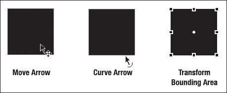
Figure 3-5. The move and curve arrows, and the transform bounding area
Again, when you are moving an object using the selection tools, you can press and hold down the Shift key to constrain the movement of the object to 45-degree increments.
With your line deselected, again place your mouse cursor over the line. Do not click the mouse button to select it. You will notice the cursor again changes, with a small arc shape appearing next to the cursor arrow as shown in Figure 3-5. This indicates that you can manipulate the curve of the line. To do this, press the mouse button and drag the line. You will see the line form a curve.
The next tool that you will use quite often is the Transform tool, which allows you to scale, rotate, and skew objects. Select the Transform tool from the Tools panel and select one of your lines. You will notice a bounding box with eight control points appear, as shown in Figure 3-5.
The control points at each corner of the bounding box can be used to scale both the height and width of the object at the same time. The control points that appear on the lines in between each corner are used to manipulate the height and width separately, with the points along the horizontal manipulating the object's height and the points along the vertical controlling the width.
When placing the mouse over these control points, you should see two-way directional arrows that indicate you can scale the object (see Figure 3-6). To scale, press the mouse button and drag the control point. Release the mouse to set the new size.
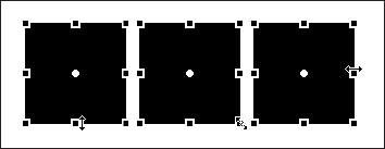
Figure 3-6. The scale cursor
If you mouse over the lines of the bounding box, you will notice the cursor change to two arrows pointing in opposite directions, as shown in Figure 3-7. This indicates that you can skew the object. Just like you did when scaling, press the mouse button and drag to skew the object.
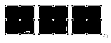
Figure 3-7. The skew and rotate cursors
Lastly, you can use the Transform tool to rotate an object. In order to rotate the object, place the mouse cursor close to the outside edge one of the control points on the corner of the bounding box. You will see the cursor change to include a small circle arrow next to the cursor arrow (see Figure 3-7). Again, press the mouse button and drag to rotate the object.
The other tools used for selecting and manipulating objects are the Subselection tool, the Lasso tool, and the 3D Rotation tool. We will introduce these tools where appropriate throughout the rest of this book.
The Pencil tool
The Pencil tool works, as its name suggests, in much the same way a pencil works. It allows you to draw freeform lines using your mouse or other pointing devices such as a graphics tablet.
The Pencil tool works in three different modes: Straighten, Smooth, and Ink (see Figure 3-8). Each mode affects the final outcome of the shape you draw and is there to assist you in creating cleaner lines.
- Straighten mode straightens lines and angles you draw.
- Smooth mode smoothes lines and angles you draw.
- Ink mode leaves the lines you draw unchanged.
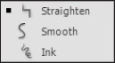
Figure 3-8. Straighten, Smooth, and Ink options
To draw using the Pencil tool, select it from the Tools panel. You should see your mouse cursor turn into a little pencil icon. Click and drag to draw your line. Try changing the Pencil tool mode to see how the lines it creates are affected. As was the case with the Line tool, holding down the Shift key while drawing a line with the Pencil tool will constrain the line to either a horizontal or vertical path.
Drawing shapes
Shapes are made from closed paths. A closed path is simply a path consisting of three or more points, where one of these points serves as both the beginning and the end of the path. Closed paths, in addition to having a stroke, can be filled with color. This color is known as the fill. Flash provides some tools for drawing the most common shapes: rectangles, ovals, polygons, and stars.
Anatomy of a shape
Shapes are comprised of two primary parts. In Flash these two parts are known as strokes and fills. You have already been using the Line and Pencil tools to create line segments. Ultimately these line segments can be closed to create shapes. When color is applied to the segment, it is referred to as a stroke.
The second part of a shape is a byproduct of closing the path. When a path is closed, you are then able to work with all of the area that exists within the path. When color is applied to the inside of a shape, it is referred to as the fill. For example, when you create a square, the stroke is the outline of that square and the fill is the inside of the square.
These two elements of a shape can be colored and manipulated independently from one another. Figure 3-9 demonstrates the concept of the stroke and the fill in terms of a total shape.
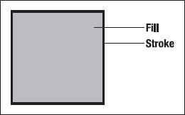
Figure 3-9. Stroke and fill of a shape
Drawing squares and rectangles
If you want to draw a square or rectangle, the quickest way to do it is by using the Rectangle tool. Select the Rectangle tool from the Tools panel. You should see the mouse cursor change into a set of crosshairs. Take a look at the Property inspector. Notice at the bottom a section titled Rectangle Options, as shown in Figure 3-10. You can add rounded corners to your rectangles by changing the values in this section. If you can't find the Rectangle tool, press R to toggle the Oval tool to the Rectangle tool.
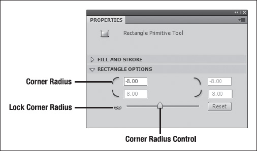
Figure 3-10. Rectangle options
Press the mouse button and drag out a rectangle on the stage. Now use the Selection tool to select the rectangle you just drew. Notice that the Rectangle Options area is no longer available to you. If you want to change the roundness of the corners of your rectangle, you will need to delete the rectangle and start again. We will show you a way around this a little later.
Drawing ovals, donuts, and pie shapes
The Oval tool allows you to draw all things round: Ovals (circles), donuts, and pie shapes. Select the Oval tool from the Tools panel, and again you will see the cursor change into a set of crosshairs. In the Property inspector you will notice a section called Oval Options. The options in this section can be used to draw donuts and pie shapes. If you cannot find the Oval tool, press O to toggle the Oval tool on in place of the Rectangle tool.
Just as before, press the mouse button and drag out an oval shape. Use the Selection tool to select your oval, and again you will see that the Oval Options area is not available in the Property inspector.
Drawing polygons and stars
What is a polygon? If you were a little distracted in geometry don't worry—so were we. A polygon is basically a shape with three or more sides (or a closed plane figure bound by three or more line segments). A star is uh . . . a little bit more complicated—look it up on Wikipedia, you'll see what we mean. Besides—you know—it's a star.
What then is a polystar exactly? It's a made-up thing Adobe used to combine two similar tools into one and it's a lot of fun. Regardless of definition, this is the tool for drawing them. We'll cover the basics here but by all means experiment and have fun.
To draw a polygon, follow these similar steps:
- Select the
PolyStartool from theToolspanel. You'll notice anOptionsbutton in theTool Settingsarea of theProperty inspector. Click this to launch the dialog shown in Figure 3-11.
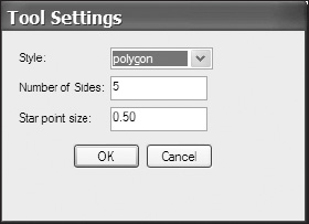
Figure 3-11. Polystar
Tool Settingsdialog - Use the
Styledrop-down to selectpolygon. Choose a number of sides (three will make a triangle, four will make a square, etc.).
- Drag on the stage, and a polygon with the number of sides you selected will be drawn there. If you chose a large number of sides, you may wind up with a shape that resembles a circle. Experiment and have fun!
To draw a star, follow these similar steps:
- Select the
PolyStartool from theToolspanel. Again, you'll notice anOptionsbutton in theTool Settingsarea of theProperty inspector. Click this to launch the dialog shown in Figure 3-11. - Use the
Styledrop-down to selectstar. Choose a number of sides. For thestarstyle this really means number of points, and theStar point sizesetting here has a huge impact on the shape you get. Setting number of sides to3and point size to.01will render a shape resembling a modern wind turbine, whereas those same three sides with a point size of 1 will look almost like a triangle. - Drag on the stage, and a star with the number of sides you selected will be drawn there. Experiment and have fun!
The primitive tools
You may have noticed that after drawing your rectangles and ovals the options are no longer available in the Property inspector. This is somewhat of an inconvenience if you decide at a later time that you want to change the radius of a rounded corner or the inner radius of your donut.
Let me introduce now the Rectangle Primitive tool and Oval Primitive tool. The primitive tools maintain the options you set in the Property inspector and make them available for editing after creation. The primitive tools also draw your shapes as primitive objects, meaning they are on separate planes and can be arranged in front or behind other objects on the stage. Other than that, they work in much the same way as objects created by the Rectangle and Oval tools.
Selecting and manipulating shapes
Once you've created some shapes on the stage, you will more than likely need to select them so you can move them around and make any necessary changes. We've already covered the Selection tool and Transform tool. These tools work in pretty much the same way with shapes, except that you can select both the stroke and the fill of a shape. Two things to make note of: Simply clicking the fill once will only select the fill. If you want to select both the fill and the stroke, double-click the fill of the shape.
Clicking a stroke once will select all segments in between two corner points. This means that if you click the stroke of a square, you will select only the stroke of the side you clicked because each point in a square is a corner point. If a curve point appears between two corner points, the two segments that make up the curve will be selected. Clicking a circle once will select the full path because all of the points in a circle are curve points. In order to select the full path of a square, simply double-click its stroke.
The next tool that can be used for selection is the Lasso tool. At times you may want to make a selection that doesn't conform to a perfect square. This might be a section of a shape, or it could be a group of items mixed in with other items. The Lasso tool allows you to hand-draw the bounds of your selection, as shown in Figure 3-12.
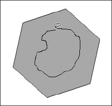
Figure 3-12. Lasso tool selection
Early in this chapter you learned that shapes are just a collection of points. These points can be manipulated in order to change the path that defines a shape. This is one of the many uses of the Subselection tool, depicted as a white cursor arrow in the Tools panel.
Draw a polygon on the stage using the PolyStar tool. Click the Subselection tool in the Tools panel to select it and place the cursor over the path of the polygon. Notice there is a small black box that appears next to the mouse arrow, as shown in Figure 3-13. This indicates you are selecting a path. Click the path to select it.
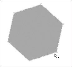
Figure 3-13. Polygon with path selection showing black square
Once the path has been selected, notice little white squares at each joint in the polygon; these are the anchor points defining the polygon's shape. Place the mouse arrow over one of the points of the polygon. The mouse arrow shows a small white box next to it. This is the indicator that you are selecting a point on a path.
When you click a point to select it, the white square changes to a solid-colored square. The color of the square will depend upon the outline color set for the layer the polygon is on. Press the mouse button and drag the point to move it. Notice the shape changes.
The Subselection tool works a little bit differently for the Rectangle Primitive and Oval Primitive tools. For the Rectangle Primitive tool, dragging a point will manipulate the corner radius of the rectangle as shown in Figure 3-14.
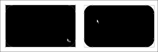
Figure 3-14. Corner radius points
For the Oval Primitive tool, there are three points. One is at the center point of the circle and controls the inner radius of the circle. The other two points, depending upon the Oval Option settings, appear to be one point along the edge of the circle, usually at the 90 degree or three o'clock position. These points control the start angle and end angle of the circle and can be move to create pie shapes (see Figure 3-15).
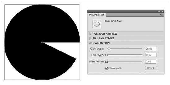
Figure 3-15. Angle handles
Strokes and fills
Now that you know how to create and edit the paths of lines and shapes, it's time to move on to editing the strokes and fills of your shapes. You may remember that the stroke of a shape is the visible outline of that shape, and the fill of a shape is the color that appears inside of the shape.
Stroke properties
At times you may require a solid hairline. At other times you may want to make a statement with a nice bold dotted or dashed line. All of this can be achieved by editing a stroke's properties in the Property inspector (see Figure 3-16).
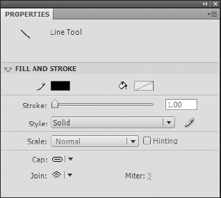
Figure 3-16. Property inspector
The best way to take a look at how a stroke's properties affect its appearance is with a star shape. Create one on the stage by using the PolyStar tool and changing the PolyStar tool's Style setting to allow you to draw stars.
- Select the
PolyStartool from theToolspanel. - In the
Property inspectorunderTool Settings, click theOptionsbutton to bring up theTool Settingswindow. - Select
staras theStylesetting and click theOKbutton to close theTool Settingswindow. - Drag out a star shape. You can hold down the Shift key while dragging out the star shape to constrain the rotation.
- Select the star's stroke by double-clicking it. Remember, clicking once will only select one of the line segments of the star since all of the star's points are corner points.
- In the
Property inspectorunderFill and Stroke, change the value of theStrokeproperty to5. Notice that this changes the thickness of your star's stroke. - Skip down to the bottom of the
Property inspectorwhere it saysCap, Join, andMiter. These settings control the shape of the stroke at each point. Cap refers to the shape of the cap that is added to the ends of an open path. Join is the shape of the joint between two line segments. - Set
Jointo each of the three options to see how they affect the look of your star's points. - Set
JointoMiterif it isn't already set to this option. - You will now see that the
Mitervalue is editable. TheMiterproperty controls the size of the miter. Set this property to0and then set it to8to see its effect. - Click the
Styledrop-down and selectDotted. You will see that your stroke has changed to a dotted line. You can click theCustombutton to edit each style's options and further refine the look of your stroke.
The Scale option controls how the stroke scales when your artwork is converted into a Library item. You can have the stroke not scale, scale horizontally only, scale vertically only, or scale both horizontally and vertically. We will discuss the Library in more detail in Chapter 4.
The last property is Hinting. At times when you are creating shapes with curves or odd angles, you will notice the stroke gets a little fuzzy. This often occurs with a thin line when it is in between pixels. By enabling Hinting, Flash will adjust the line's anchor points to fall on full pixels, preventing the lines from becoming fuzzy.
Color properties and fills
There are several avenues to take when setting colors in Flash. For some it can be a little confusing. The good news is whichever route you take, the end result is the same. You may have noticed two of the ways of changing colors as you've gone through this chapter: color pickers for stroke color and fill color appear in both the Tools panel and the Property inspector. You can use either one of these two quickly to change the color of your artwork. The stroke color picker is depicted with a little pencil icon and the fill color picker is depicted with a paint bucket icon (see Figure 3-17).
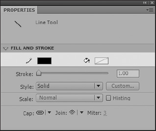
Figure 3-17. Color pickers
Clicking either one of these color pickers will bring up a Color palette with web-safe color swatches you can choose from. You can also use the mouse to sample any color on the screen. Yes, if you really like the gray used for the Flash interface, you can sample that color too. NICE!
You will also see options to enter a hex value to set color, as well as set the transparency or alpha of the color. If you want a little more control over your color selection, you can click the Colors icon in the Color palette, which is represented by a multicolored circle. This will bring up the Colors dialog with a variety of different palettes, color wheels, and color spectrums to choose from.
Lastly, if you want to clear the fill or stroke color, you can click the No Color button, depicted by a white square with a red diagonal line going through it.
The Color panel
Another way of choosing colors is with the Color panel. If the Color panel is not already open, you can open it by selecting Window ![]()
Color in the menu bar or by pressing Shift+F9.
Again, you will see the color pickers for the stroke and fill. If you click the pencil icon, you will make the stroke active, and any color settings you set in the Color panel will be applied to the stroke color. The same goes for clicking the paint bucket icon.
Under the color pickers for the stroke and fill, you will see three more icons (see Figure 3-18). One should look familiar; it is the No Color button. The other two, which are also available under the color pickers in the Tools panel, are the Black and White button and the Swap Colors button.
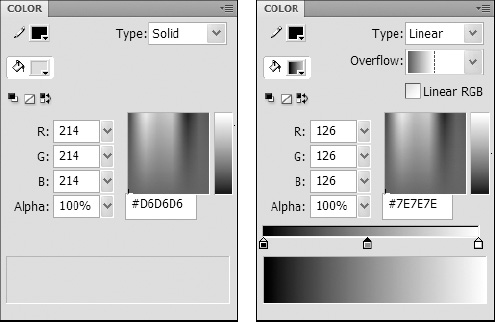
Figure 3-18. The Color panel. On the right, the Color panel has the gradient options activated.
The Black and White button resets the fill and stroke colors to their default values, black stroke and white fill. The Swap Colors button does just as its name suggests: it swaps the fill and stroke colors, so the fill color becomes the stroke color, and the stroke color becomes the fill color.
To set your colors you have several options. You can click the color picker, set the RGB values for the color, set the hex value for the color, or select the color from the color spectrum. You can also set the alpha transparency of the color by specifying a percentage, where 100% is opaque and 0% is completely transparent.
Next, notice the Type drop-down. This is where you can specify the stroke or fill type. The options you have here are None, Solid, Linear, Radial, and Bitmap. None and Solid are pretty self-explanatory. Linear and Radial are types of gradients. You would use Bitmap if you need separate pixels that can be manipulated individually. Bitmaps will be covered in more detail in the next chapter.
Select Linear from the Type drop-down, and you will notice a gradient bar appear. You will use this bar to define your color gradient. Under the bar you will see little arrow sliders with colored squares in them—this is where you set the colors in your gradient.
Click one of the arrow sliders and use the color spectrum to select a new color. You can set the color using any of the options available to you in the Color palette. You can also double-click the arrow slider to set its color as well.
To add another color to the gradient bar, simply click anywhere on the bar there isn't already a slider arrow. You can move any of the slider arrows by dragging it. Doing this adjusts the length of the gradient transition from one color to the next.
The Overflow drop-down gives you options for specifying how the gradient fills to the edges of a shape. The Extend option will extend the first and last color to the edge of the shape. The Reflect option will start another gradient using the adjacent color as the start color (A ![]() B
B ![]() B
B ![]() A). The
A). The Repeat option will simply repeat the gradient all the way to the edge (A ![]() B
B ![]() A
A ![]() B).
B).
The Panel Options button, located in the top-right corner of the panel, gives you two options. The first is the ability to change the Color Mode setting for the Color panel. The default is RGB (red, green, blue), which most people are familiar with. The other is HSB (hue, saturation, and brightness). The second option is Add Swatch, which allows you to add the current color to the Swatches panel.
The Swatches panel
The Swatches panel is another tool you can use to set colors, and it consists of a collection of color swatches called a color set. The Swatches panel makes it easy to quickly select predefined colors. To open the Swatches panel, select Window ![]()
Swatches or press Ctrl+F9 (Cmd+F9 on the Mac).
As shown in Figure 3-19, the default colors in the Swatches panel are web-safe colors and a couple of gradients. The Swatches panel also allows you to add your own color swatches and save them for use later.
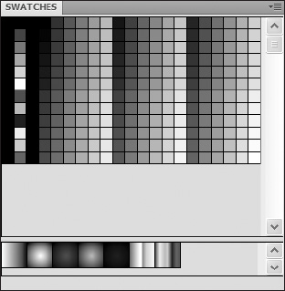
Figure 3-19. The Swatches panel
There are several ways to add colors to the Swatches panel. To add the currently selected color to the Swatches panel, you can click the Color Panel Options button and select Add Swatch.
- Open the
Colorpanel (Window
Color). - Click the paint bucket icon to select the fill color.
- Select your favorite color by editing the RGB or hex values, or select your color from the color spectrum.
- Click the
Color Panel Optionsbutton and selectAdd Swatchas shown in Figure 3-20.
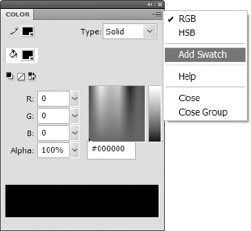
Figure 3-20. Selecting the
Add Swatchoption from theColor Panel Optionsmenu - Open the
Swatchespanel. Notice that your color was added to the collection of colorswatches. You may need to resize the Swatches panel or scroll down to see your newly created swatch. This swatch will also be available when using the color pickers in theColorpanel orToolspanel. - In the
Swatchespanel, notice that the far-right column is all gray. This is an empty area of theColorpanel. Position your mouse over this gray area, and your mouse cursor should change into a paint bucket (see Figure 3-21). This indicates you can click to add the currently selected color. Click the gray area to add another color swatch.
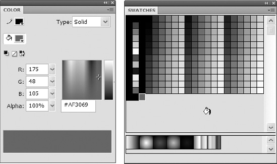
Figure 3-21. How the
Colorpanel (left) can be used to add a swatch to theSwatchespanel (right) - You should now have two custom color
swatchesin your Swatches panel. Position the mouse cursor over one of these newly created swatches. Your mouse cursor should change into theeyedroppericon. This indicates that you can select the color swatch. Click the color swatch to select it. - To delete a color swatch, select a color swatch in the
Swatchespanel, click theOptionsbutton at the top right of theSwatchespanel, and selectDelete Swatch. - To duplicate a color swatch, select your other color swatch in the
Swatchespanel. Click theSwatches Panel Optionsbutton and selectDuplicate Swatch. - If you want to set the colors back to the default set, select
Load Default Colorsfrom theSwatches Panel Optionsmenu.
If you add swatches to the Swatches panel, they will be lost when you close Flash. If you want to keep your colors for use later, you can save your color set by selecting Save Colors from the Swatches Panel Options menu. Provide a file name and location to save the file.
The next time you open Flash, you can load these colors by selecting Add Colors or Replace Colors from the Swatches Panel Options menu. If you don't want to have to load your colors every time you open Flash, you can choose Save as Default, and your color set will load automatically when Flash is opened.
If you want to start with a clean color set, you can select Clear Colors from the Swatches Panel Options menu. This will allow you to create a completely custom color set that doesn't include the swatches already included in the default set. These sets can then be added into the Swatches panel as needed.
The Paint Bucket tool
Now that you've learned how to choose colors, let's take a look at the tools for applying those colors to your artwork. The Paint Bucket tool allows you to fill shapes with color and can be employed to quickly fill multiple shapes with the same color. You can use it with solid fills, gradients, and bitmap fills. (We will cover bitmap fills in Chapter 4.)
- Click the
Black and Whitebutton in theToolspanel to set your stroke and fill to the default colors. - Using the
Ovaltool, draw three ovals on the stage. Notice that the ovals are created with a black stroke and a white fill. - Select the
Paint Buckettool and using one of the fill color pickers on the toolbar, as shown in Figure 3-22, to change the color of your fill.
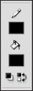
Figure 3-22. Fill color pickers on the tool bar
- Using the
Paint Buckettool, click the fill of each of your three ovals to apply the new color. - The
Paint Buckettool can also be used to fill in empty shapes as well. Click theSelectiontool and select the fill of one of your ovals. Press Delete to delete the fill. - Select the
Paint Buckettool again and click inside of the oval whose fill you just deleted. Again, you will notice your new color has been applied to your fill. - You can apply gradient fills to your shapes with the
Paint Buckettool as well. In the Color panel, selectLinearfrom theTypedrop-down and set the start and end color for your gradient, as shown in Figure 3-23. - Click the fill of one of your ovals. Notice that the gradient is applied horizontally across your oval, and the gradient is evenly distributed. If you want more control over the direction of your gradient and distribution of colors, you can press the mouse button inside the oval where you want your gradient to start and drag in the direction you want your gradient to run. You will notice a line that runs from your starting point to the
Paint Buckettool. This line indicates the direction your gradient will run.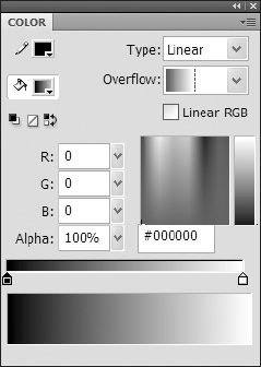
Figure 3-23. The
Gradient Colorpanel can be used to apply gradient fills to shapes. - Release the mouse button to set your gradient.
- You can drag the end point of your gradient out past the bounds of your shape. Click inside of the oval that is in middle of your three ovals and drag out your gradient to one of the other three ovals. Release the mouse button in the center of the oval.
- The
Lock Fillmodifier, depicted by a gradient bar with a lock on it, is located at the bottom of theToolspanel (see Figure 3-24). TheLock Fillmodifier locks the gradient you just dragged out and will treat your gradient as if it filled the whole stage. This allows you to apply gradients across multiple shapes on the stage. Click each of the ovals to set their new fill. Try this with five or more shapes on the stage to better see the transition.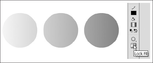
Figure 3-24. Three circles with
Lock Fillapplied, linking their fills - Click the
Lock Fillmodifier again to deselect it.
Another modifier for the Paint Bucket tool is the Gap Size modifier (see Figure 3-25). Using this modifier you can fill in open paths that have small gaps in them. This works well for hand-drawn shapes that might not quite be closed.
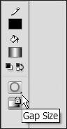
Figure 3-25. Gap Size modifier button
- Select the fill of one of your ovals and delete it, leaving just the stroke.
- Using the
Selectiontool, drag out a selection to select a small portion of the stroke, between 5 to 10 pixels. Delete this selection to create a small gap in the stroke, as shown in Figure 3-26.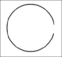
Figure 3-26. Oval with gap in stroke
- Using the
Paint Buckettool, click inside of the circle with the gap in its stroke. Notice the fill color was not applied. - Hold down the mouse button on the
Gap Sizemodifier button. You will see four options pop up:Don't Close Gaps, Close Small Gaps, Close Medium Gaps, andClose Large Gaps, as shown in Figure 3-27. Select theClose Large Gapsoption. You will see the icon for theGap Sizemodifier change from a closed circle to a circle with a gap in it.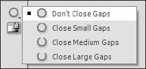
Figure 3-27.
Gap Sizemodifier options - Click inside of the oval from which you just you deleted a section of the stroke. This time the color is applied.
- Save your file (
FileSave) as3circles.fla.You will continue using this file in the next section.
The Ink Bottle tool
In much the same way the Paint Bucket tool works for fills, the Ink Bottle tool is used to apply stokes to shapes. Whereas the Paint Bucket tool is strictly used for applying color, the Ink Bottle tool can be used to apply stroke properties such as stroke weight, style, and color.
The Ink Bottle tool is grouped with the Paint Bucket tool in the Tools panel. If you look at the Paint Bucket tool icon, you will notice a small black triangle in the bottom-right corner. You will also notice this same black triangle on some of the other tools in the Tools panel. The black triangle indicates that there are tools grouped together in a fly-out. To access these tools, simply click and hold down the mouse button on the triangle icon, and the fly-out will appear.
- If it is not already open, open the file
3circles.flathat you were using in the examples in the preceding section. - Select the
Ink Bottletool from theToolspanel. If the icon for this tool is not showing, click and hold down the mouse button on thePaint Buckettool to access it (see Figure 3-28).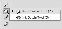
Figure 3-28.
Ink Bottletool fly-out - In the
Property inspectoryou will see all of your stroke properties. Change the stroke color, set the stroke width to 5 px, and selectDashedfrom theStyledrop-down. - Click one of your oval shapes. You will see the stroke change for the shape.
The Gradient Transform tool
The Gradient Transform tool is used to scale and rotate the gradient fill of a shape. When you select a gradient fill with the Gradient Transform tool, you will see a couple of transform handles that allow you to edit the way your gradient looks (see Figure 3-29).
At the center is a small white circle. Dragging this circle will move the gradient center point and shift your fill. The two lines indicate where the start and end colors of your gradient are at 100%. Along one of the lines is a white square with an arrow in it. Dragging this square will scale the transition of your gradient. At the end of the same line you will see a circular arrow; dragging this transform handle will rotate your gradient.
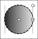
Figure 3-29. Gradient Transform tool transform handles
The Kuler panel
If you find it hard to make it through your work day without a small dose of the social Web, the Kuler panel (shown in Figure 3-30) is your ticket to getting that fix. As the About section of the Kuler panel states, "kuler is an online community for colors and inspiration, to explore, create, and share color themes." This can be an excellent resource for you right inside of the Flash IDE in putting Color palettes together for your projects.
The Kuler panel makes available an extensive collection of user-created Color palettes that you can browse and search through. When you find palettes you like, you can save them for easy access. You can also use the color wheel to create your own palettes and save them locally or to the kuler web site.
The Kuler panel requires an Internet connection to access the kuler web site but does allow you to save your favorite Color palettes locally and even transfer those Color palettes to the Swatches panel.
The Kuler panel can be accessed by selecting Window ![]()
Extensions ![]()
Kuler.
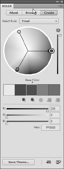
Figure 3-30. The Kuler panel
Advanced drawing
Now that you are familiar with the basic tools and drawing skills in CS4 Flash, let's look at some more advanced topics that will let you become a Flash artist extraordinaire, or at least put you on the right "path," pardon the pun.
The anatomy of a path
As mentioned previously, a path is a collection of two or more points connected by lines. The points that make up a path are referred to as anchor points. The area between two anchor points on a path is known as a segment. The anchor point in between two segments on a path is known as a joint.
Each point within a path can be either a corner point, a curve point, or a corner-curve point. The type of points that make up a segment determines the shape of the line between two points and the shape of the joint between two segments.
- Corner points: These create straight lines and sharp corners between segments. The four points in a square are all examples of corner points.
- Curve points: These create curved lines and curved corners between segments. Manipulating curve points affects the segments on either side of the point. This means that when you change the curve of one segment, it affects the curve of the opposite segment. This creates a nice, fluid transition between the two sections. The four points that make up a circle are all examples of curve points.
- Corner-curve points: As you might guess, these are a combination of the two preceding types of points. They are used when you want to independently control the curve of each line segment.
When you select a curve point with the Subselection tool, you get curve handles that are used to manipulate the shape of the curve, as shown in Figure 3-31. You can manipulate the curve handles by moving the tangent points at the end of each curve handle. Each curve handle corresponds to one of the segments adjacent to the selected curve point. For corner-curve points, you will see only one curve handle. Yes Martha, even curves have corners.

Figure 3-31. This figure represents a rounded path with curved corner points.
The Pen tool
The Pen tool is used in Flash to create complex paths. The Pen tool gives you more control over the shape of a path during and more notably after creation. This gives the Pen tool a considerable advantage over the Pencil tool in creating paths, especially when "tracing" an image for illustration. Even if you feel you have more control creating shapes using the Pencil tool and a stylus or you don't plan on doing much tracing, it is important to get comfortable with the concepts we describe here, as they are the basis for working with and manipulating points of other shapes as well.
- Open a new Flash file (
FileNewFlash File (ActionScript 3.0)). - Click the
Black and Whitebutton in theToolspanel (see Figure 3-32) to change your colors to the default colors.
Figure 3-32.
Black and Whitecolor defaults button - Select the
Pentool from theToolspanel. It is depicted as a fountain pen tip (see Figure 3-33).
Figure 3-33.
Penicon - Click the stage to set the first point of your path.
- Create two more points on the stage by clicking to set your points. Create an open triangle shape with your three points, as shown in Figure 3-34. Keep the
Pentool selected—you aren't finished creating your path just yet. You will see the shape of the path you are creating as you add points. So far, you have just created three corner points. Notice the joint created by the second point is sharp.
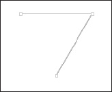
Figure 3-34. Open path triangle shape
- Create another point on the stage, but this time instead of simply clicking, hold down the mouse button and drag. You will see a curved path is created. Drag out a curve that you are happy with and release the mouse button to set the point.
- You can edit the path while you are creating it by using modifier keys. Holding down the Ctrl key (Cmd on Mac) will allow you to move points. The mouse cursor will change into a black arrowhead. Do this now and move some of your points around. Move the curve handles to change the shape of the curve you just created. Notice that moving one curve handle also changes the curve handle on the opposite side of the anchor point. You just created a curve point.
- Create another point on the stage and again hold down the mouse button and drag out a curve. At times you will want to create a straight line after you create a curve. To do this you need to create a corner-curve point. Place the mouse over the point you've just created. A small "V" shape will appear next to the pen cursor. Clicking the point will convert the point to a corner-curve point. Notice your anchor point now has only one curve handle (see Figure 3-35).
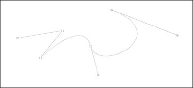
Figure 3-35. Corner-curve point
- Click the stage to create another point. The line that you just created is straight.
- Now let's back up two points. Counting the point you just created, follow the path back to the third point (it will be the curve point you created earlier). Remember that when you moved the curve handles on this point, both curve points moved in tandem. If you want to unlink the two curve handles so they can be moved independently, hold down the Alt key (Option on the Mac). The cursor will change into a "V" shape. With the Alt key held down, drag the curve handle to move it. The curve handle now moves independent of the curve handle on the opposite side of the point and only affects the curve on the same side of the point as the handle you moved (see Figure 3-36).
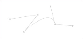
Figure 3-36. Independent curve handles
- The Alt key can also be used to convert a curve point to a corner point, or a corner point to a curve point. You do this by holding down the Alt key and clicking the point you want to convert. Click the curve point now to convert it to a corner point. You now have a sharp corner (see Figure 3-37).
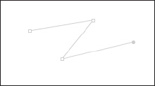
Figure 3-37. After conversion to a corner point
- Back up two more points to the second point you created, the peak of your "triangle." Holding down the Alt key, click, and drag the point to drag out the curve handles. You now have a curve point (see Figure 3-38).
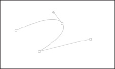
Figure 3-38. After conversion to a curve point
- To close off a path, place the mouse over the first point on your path. You will see a small circle appear next to the Pen cursor, as shown in Figure 3-39. This indicates that you are closing the path. Click the point to finish off your path.
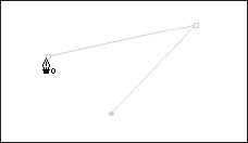
Figure 3-39. Close path cursor
Manipulating paths
So you just learned how to use the Pen tool to create a complex path and how to edit the points and paths during creation. What if you want to edit the path after you've created it? The same tools you accessed using the modifier keys during the creation of your path are also available in the Tools panel.
The first tool is the Subselection tool, which we covered earlier in this chapter. You can use the Subselection tool to move your anchor points and curve handles to change the shape of your path. The same modifier keys you used earlier are available when editing paths with the Subselection tool.
The next tool is the Convert Anchor Point tool. You can access this tool by holding down the mouse button on the Pen tool icon to bring up the fly-out. The Convert Anchor Point tool is used to convert your curve points to corner points, and vice versa. It works in the same manner as the Alt modifier key used earlier.
The other two tools are the Add Anchor Point tool and Delete Anchor Point tool, accessible in the same fly-out under the Pen tool. As their names suggest, these tools are used for adding and deleting points on your path.
To add a point, select the Add Anchor Point tool and click where you want to add a point on your path. Again, you have access to the modifier keys to edit the point using this tool. To delete a point, select the Delete Anchor Point tool and click the point you want to delete.
Summary
In this chapter we covered an incredible amount of ground with respect to creating shapes with vector tools in Flash. This should come as no surprise since Flash is a vector drawing tool. You learned about the following topics:
- Vector vs. bitmap
- Drawing modes
- Object drawing
- Drawing tools
- Drawing shapes
- Strokes and fills
- Color properties
- Manipulating lines