
Chapter 13
Pinball Game
I'd like to put the Box2D physics engine to good use, so in this chapter you'll be making an actual pinball game. Pinball tables are all about using our physical world and turning that into a fun experience. With a physics engine, however, you're not just limited to real-world physics.
Some elements of the pinball table, such as bumpers and balls, can be created by simply choosing the right balance of friction, restitution, and density. Others need joints to work—a revolute joint for the flippers and a prismatic joint for the plunger. And of course, you'll need lots of static shapes that define the collision polygons of the table.
Since it would be impractical to define collision polygons in source code, at least for the level of detail necessary to build a believable pinball table, I'll introduce another useful tool: PhysicsEditor. With that, you can create collision polygons by simply drawing the vertices or, even faster, let PhysicsEditor trace the shape's outlines with a single mouse click.
At the end of this chapter, you'll have a fully playable pinball game, as depicted in Figure 13–1.
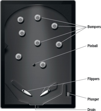
Figure 13–1. The pinball table built in this chapter
Shapes: Convex and Counterclockwise
Let's start with the requirements of collision polygons. The first thing you need to be aware of when defining collision polygons for Box2D and Chipmunk is that these engines expect the collision polygons to have the following properties:
- Vertices defined in a counterclockwise fashion
- Polygons as convex shapes
A convex shape is a shape where you can draw a straight line between any two points without the line ever leaving the shape. This is opposed to concave shapes, where a straight line between two points can be drawn such that the line is not entirely contained within the shape. See Figure 13–2 for an illustration of the difference between convex and concave shapes.
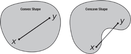
Figure 13–2. Convex and concave shapes
Defining the vertices of a convex shape in a counterclockwise fashion can be illustrated by drawing a convex shape in your mind. You place one vertex anywhere and then go left to place another. Then go down and to the right, and you will have drawn a rectangle in a counterclockwise fashion. Or place another vertex and then go right, up, and then left, and you will have drawn a counterclockwise shape. It doesn't matter where you start with the first vertex, but it's very important to follow the counterclockwise orientation of vertices.
Fortunately, if you're working with PhysicsEditor, you don't have to care about polygon vertex order (orientation) or whether the polygon is convex or concave. PhysicsEditor automatically takes care of that for you transparently. PhysicsEditor will split concave shapes into one or more convex shapes. The physic objects loader shipped with PhysicsEditor then assigns all the shapes to a single Box2D body. It's still good practice to try to avoid shapes to be split in order to have as few collision shapes per body as possible to get the best performance.
TIP: How do you know if you made a mistake and accidentally created a clockwise-oriented or concave collision shape? Well, every physics engine reacts differently. Some will tell you up front by throwing an error. But in the case of Box2D, if a moving body hits a collision shape that is not well formed, the moving body will simply stop moving when it gets close to that shape. If you ever see that effect happening in your Box2D game, check the nearby collision polygons.
Working with PhysicsEditor
Armed with the knowledge about properly defining collision polygons, it's time to check out the PhysicsEditor tool, which you can download from www.physicseditor.de. After opening the downloaded PhysicsEditor disk image and dragging PhysicsEditor.app to your application's folder, you are ready to run PhysicsEditor (see Figure 13–3). In the PhysicsEditor disk image, you will also find a folder named Loaders, which contains the loader code (shape cache) for Box2D and Chipmunk plist files created by PhysicsEditor. You will be using the GB2ShapeCache class in the example projects of this chapter in order to load the shapes created by PhysicsEditor.
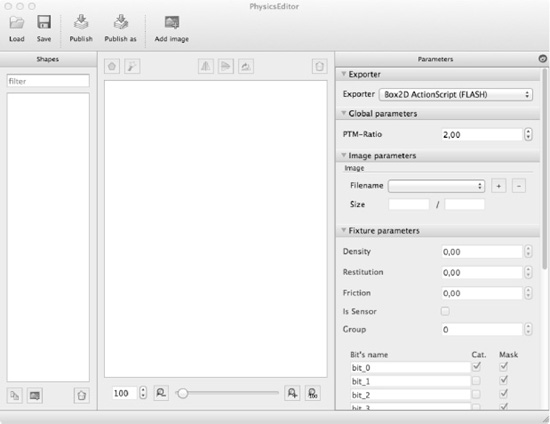
Figure 13–3. The PhysicsEditor application
You should now drag and drop the PNG files located in the PhysicsBox2D03project's Assets/pinball folder onto the leftmost pane in PhysicsEditor, which is labeled Shapes.
NOTE: You will be using only the HD resolution images to create physic shapes. It is not necessary to create separate HD and SD resolution physics shapes. The physics simulation world is independent from the graphical representation of the objects and thus independent of the screen resolution.
The first thing you should modify in PhysicsEditorare the settings for the exporter. PhysicsEditor can export to several game engines, supports both Box2D and Chipmunk physics engines, and even allows you to create your own custom export format. To write files compatible with cocos2d, you must set the Exporter setting on the rightmost pane to Box2D generic (PLIST). It is important to set the exporter first since it enables or disables some features of the PhysicsEditor GUI depending on the targeted physics engine's capabilities.
Next you should set the PTM-Ratio setting to 240. This value's unit is in pixels per meter, meaning 240 pixels will equal 1 meter in the Box2D physics simulation world. The dimensions of the Box2D physics world matters because Box2D is optimized to work best with objects of 1 to 10 meters in size. You can easily run a simulation with larger or smaller objects. However, Box2D loses precision and can show odd behavior when you have very large (tens or even hundreds of meters) or very small objects (small or tiny fractions of a meter).
Since we are using high-resolution images in PhysicsEditor, the PTM-Ratio of 240 will create a pinball table that is 4 meters high (960 Retina resolution pixels divided by 240) and 2.6 meters wide (640 Retina resolution pixels divided by 240). The actual pixels to meter ratio in cocos2d will be half the PTM-Ratio setting of PhysicsEditor, in this case 120 pixels per meter. This is because the cocos2d coordinate system is in points, which means both the standard-resolution display and Retina displays have the same dimension: 320x480 points. A point equals 1 pixel on standard displays and 2 pixels on Retina displays. The size of the table in the Box2D physics world is unaffected by the actual screen resolution. If you work only with standard resolution images and have Retina support disabled in your app, the PTM-Ratio setting in PhysicsEditor will equal that in Cocos2D.
Defining the Plunger Shape
Let's start with the plunger, the spring that kicks the ball into play. Select the plunger image on the leftmost pane and click the Add polygon button on the center view's toolbar. This creates a new triangle shape on the center working area and highlights it. Since we need a rectangular shape, double-click one of the sides to add a fourth vertex. In case you added too many vertices, you can right-click or Option-click a vertex and choose to Delete point to remove it.
You should move the four vertices to the four corners of the plunger by clicking and dragging them. Create a rectangular shape that encompasses the entire plunger, including the spring. Make the rectangle cover the complete plunger, including the spring. This will avoid problems when the ball by accident falls below the plunger's head.
You may have noticed the little bluish circle with the + inside. This is the anchor point of the shape, which coincides with the anchor point of the shape's sprite. Later, when we position the shape in cocos2d, the shape's anchor point will be centered on the coordinates that we provide.
You will want to move the anchor point to the bottom center of the plunger image to make it easier to position the plunger. You can drag the blue circle, but in many cases, you will want to place it very accurately. In those cases, you can modify the anchor point's absolute pixel position or the relative position in the Parameters pane under Image Parameters.
In Figure 13–4, you'll see the plunger shape being edited.
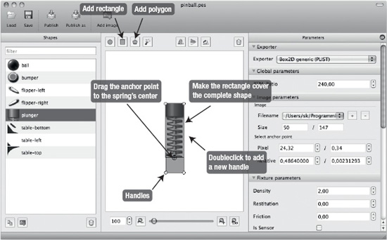
Figure 13–4. Manually defining a shape in PhysicsEditor
Instead of creating the shape from a polygon, you could have also used the Add Rectangle button. But then I wouldn't have been able to tell you how to add or delete vertices and how to drag them.
You can and should also set the collision bits for the plunger under the Fixture parameters section in the Parameters pane. The collision bits allow you to define which shapes collide and which don't. The collision bit settings will be used to prevent the plunger from colliding with any shapes but the ball.
To make working with collision bits easier, you can change the names of collision bits. The collision bit names are not exported; they serve only to remind you what each bit is used for. By default, the bits are called bit_0 to bit_15. You will want to change the names of the first five bits to Ball, Bumper, Flipper, Plunger, and Wall, respectively.
Box2D shapes collide with each other only when the category bit (the check box column labeled Cat.) and the mask bit (the check box column labeled Mask) of both shapes are set. Typically you will want to assign each shape to just one particular category. In the case of the plunger, make sure that only the category bit for the Plunger category is set. In other words, you're assigning the plunger's shape to be in the Plunger collision bit category. With the Mask check box, you then set with which other categories this shape is allowed to collide with. In the case of the plunger, you should set only the Mask check box for the Ball category, allowing the plunger to collide with the ball. Figure 13–5 shows the correct settings for the Plunger collision category and mask flags.
NOTE: So far, the plunger would collide with the ball, but the ball would not collide with the plunger. You'll have to keep in mind that defining collisions is a two-way process, and in this case, you'll still have to put the ball in the Ball category and check the ball's Mask bit that corresponds with the Plunger category to have both ball and plunger collide with each other.
You can also set the mask bit for the same category, allowing multiple objects of the same category to collide with each other. In the case of the ball shape, it would make sense to set the Mask bit of the Ball category in order to allow ball-to-ball collisions. This will be useful if you want to extend the pinball game to support a multiple balls on the table at the same time.
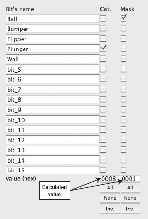
Figure 13–5. Collision parameters for the plunger
Below the Cat. and Mask columns, you'll find the buttons All, None, and Inv., which allow you to check all, uncheck all, or invert the check boxes' checked status. They are helpful to avoid clicking possibly dozens of check boxes one after another.
Defining the Table Shapes
The pinball table consists of three separate shapes named table-bottom, table-left, and table-top. The table background image is split up to make it easier to edit its shapes and to make it easier to create different pinball layouts without having to replace the entire image.
Select the table-top image in the Shapes pane to start editing the shape for the topmost part of the pinball table. As you can see in Figure 13–6, it's a concave shape. With the manual method used to define the plunger, it would be difficult and error-prone to create all the vertices of this round shape manually, let alone ensuring that the resulting shape is convex. PhysicsEditor makes this a lot easier for you: it will trace the shape's outline and create a suitable shape with a single mouse click!
Above the center pane there's a magic wand icon in the toolbar called the Shape Tracer. Click the wand icon to open the Shape Tracer dialog shown in Figure 13–6.
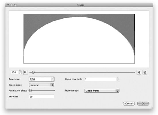
Figure 13–6. The Shape Tracer creates shapes automatically.
The Shape Tracer shows the shape's image and an overlay of the shape it is going to create when you click the OK button. Below the image you'll find a slider and buttons to the left and right of the slider that control the zoom level of the image. The image zoom settings do not affect how the shape is created.
The most important setting you will want to adjust in the Shape Tracer is the Tolerance setting. Tolerance changes how accurately the image is traced to create a shape, which directly influences the number of vertices used for the shape. The number of vertices of a shape in turn influence the performance of the physics simulation. Generally, you should always strive to achieve adequate collision responses with the least amount of vertices. The more important the accurate collisions are for your game, the more vertices you will want to allow for some objects. At the same time, if you add many objects using the same shape, using a shape with fewer vertices will result in better performance.
By experimenting with the Tolerance setting, I found that a good compromise in this case is a Tolerance value of 4,0. This creates a shape with 18 vertices, and it's the highest Tolerance value that still traces the image's shape quite accurately. The default Tolerance setting of 1,0 would have created a shape with 31 vertices, so I was able to save 13 vertices. But you'll notice if you cycle through the Tolerance values that even a Tolerance value of only 1,5 will already cut down the number of vertices to 20.
TIP: The Frame Mode setting in the Shape Tracer can be used to create a shape for an animation (sequence of images). To create an animation in PhysicsEditor, you'll have to add more image files to a shape under Image Parameters in the Parameters pane, in the default PhysicsEditor window. By clicking the + button next to the Filename setting, you can add additional images to a single shape; then you can have the shape trace create a shape that is either the intersection or the union of each animation frame's shape.
When you're satisfied with the traced shape, click the OK button to close the Shape Tracer dialog. This will create the new shape. You still have to perform a quick manual tweak for the pinball table's collisions to work smoothly. Since the screen area will define the collision on the sides of the pinball table, you should drag the lower-left and lower-right corner vertices as well as the upper-left and upper-right corner vertices slightly outside the screen area and downward and upward, respectively, so that they are clearly outside the black frame border drawn around the table-top image. See Figure 13–7 for a visual hint.
By extruding these two vertices, the shape will form a soft transition to the sides of the screen borders. Without extruding these vertices, the ball might get reflected from the tips of these vertices because of slight inaccuracies that are always present in physics simulations.
Now move the anchor point (the blue circle with the + inside) to the top-left corner, preferably by using the anchor point settings in the Parameters pane under Image Parameters. Set the Relative values to 0,0 and 1,0, respectively, to move the anchor point to the top-left corner. This anchor point position will later allow you to align the image exactly with the screen border by simply positioning it to 0,480 in point coordinates.
NOTE: If you do not see the anchor point circle and there are no anchor point settings under Image Parameters, you do not have the Exporter setting in the Parameters pane set to the Box2D generic (PLIST) format.
The last step is to adjust the collision bits of the table-top shape. Check the category (Cat.) check box of the Wall row and then set the Mask check box in the Ball row. This will enable collisions of the pinball table with the ball. Accordingly, you'll have to set the same collision bits for the table-left and table-bottom shapes because they are all part of the Wall category and should collide with the Ball category.
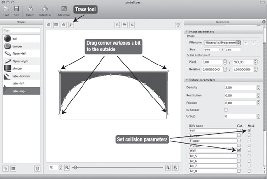
Figure 13–7. Finalizing the table's top shape
Use the Shape Tracer to create the shape for the table-left image in the same way. Under Image Parameters, move the anchor point to Pixel coordinates 0,0 and 50,0. Don't forget to set the collision bits just like earlier for table-top.
Now let's trace the shape for the table-bottom image. This requires a few additional steps because the table-bottom image actually consists of four individual, disjointed elements that need to have individual shapes. The version 1.0.4 of PhysicsEditor traces only contiguous shapes so you need to open the Shape Tracer a total of four times. Each time you open the Shape Tracer, click the part of the image that you want to trace and then click the OK button to create the shape. A Tolerance setting of 4,0 works well for all four shapes. You should end up with four shapes covering all the four elements of the table-bottom image. Don't forget to set the collision bits exactly like you did for table-top, as shown in Figure 13–7.
Defining the Flippers
Select the image named flipper-left, and open the Shape Tracer. You will notice that the resulting shape initially suggested by the Shape Tracer does not make much sense; the shape is a lot larger than the image would suggest.
This is because the image has glow and shadow effects that create an aura around the shape itself and that is nearly invisible on a light background. To enable the Shape Tracer to create a better shape, you need to adjust the Alpha threshold setting. The default value is 0, which means that all pixels that are not entirely transparent will be considered when the shape is traced. In this case, we want only the fully opaque pixels to be considered for the shape. If you set the Alpha threshold to 254, as in Figure 13–8, you'll get a much better result.
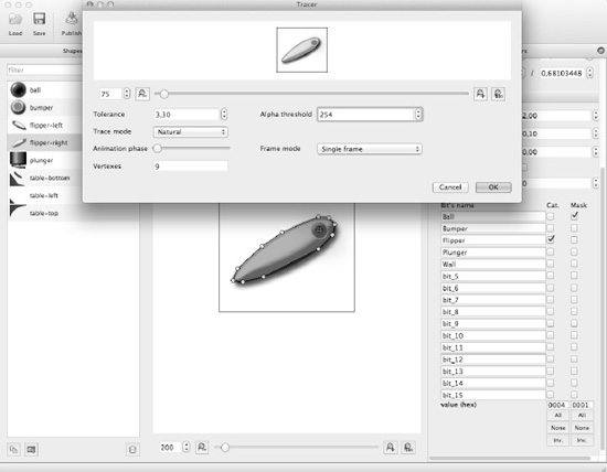
Figure 13–8. Tracing the shape of a flipper with an alpha threshold to ignore the image shadow.
TIP: If for any reason the Shape Tracer result is not what you want and neither the Tolerance nor the Alpha threshold setting allows you to fix the shape, you can still manually edit the shape after closing the Shape Tracer. Just click any vertex and drag it. You can also double-click a vertex to remove it or double-click a line segment between two vertices to add a new vertex.
Repeat the same process for the flipper-right image. And don't forget to set the collision bits for both flippers. You will want to check the Flipper category and the Mask check box in the Ball row. Figure 13–8 shows the correct collision bit settings.
The anchor point of the left flipper should be set to Pixel coordinates 27,78 and 97,79 for the right flipper.
Defining the Bumper and Ball
The ball and bumper images are both circles, so you can use the Add Circle command from the toolbar to create a circle shape. The circle shape has only one “vertex” that acts as a handle to resize the circle shape.
Starting with the bumper, change the circle shape's size and position so that it overlaps the solid part of the bumper while ignoring the bumper's shadow. Set the bumper's anchor point to Pixel coordinates 33, 42 so that the anchor point is centered on the bumper. Set the collision bits category check box next to Bumper, and set the Mask check box of the Ball row.
To simulate the bumper's bounce effect, you should also modify the Fixture parameter in the Parameters pane labeled Restitution. Restitution is the amount of elasticity with which an object repels other colliding objects. A restitution of 0 means that the collision is not elastic at all and will stop the incoming object. A restitution of 1 simulates a perfect elastic collision, allowing the colliding object to continue with the same speed after colliding.
Since we want to simulate an additional repelling force coming from the bumper, we can simply use a value of 1,5 or higher in order to have the colliding object move away from the collision at a higher speed than the speed it had when it impacted. In real life, this would be a violation of Newtonian physics and is in fact impossible. So, don't tell your physics teacher!
Lastly, create the circle shape for the ball image. Size and position the circle shape so that it overlays the entire ball image. You should set the anchor point Relative values to 0,5 and 0,5.
As for the ball's collision bits, you should set the category check box next to Ball and check all the Mask check boxes for the other categories: Ball, Bumper, Flipper, Plunger, and Wall. You can also simply click the All button at the bottom of the Mask column. Since we don't use the other bits, it doesn't matter if they are checked, too.
Some of the ball's Fixture Parameters affect how the ball behaves on the table. I set the Density to 8,0,Restitution to 0,3 and Friction to 0,7. These settings give the ball just a little bit of bounce. Feel free to tweak these settings and observe how the ball's behavior changes.
Save and Publish
Lastly you should save the current PhysicsEditor .pes file. You can later open the .pes file to continue editing shapes. You should not add the .pes file to your Xcode project; it is usedonly by PhysicsEditor.
To use the shapes in cocos2d, you will have to use the Publish button. This creates a .plist file that the GB2ShapeCache class distributed with PhysicsEditor can read. For the PhysicsBox2D03 project, I published the shapes as pinball-shapes.plist in theResources folder of the project. Add this file to the Resources group in Xcode.
Programming the Pinball Game
Now we can move on to the implementation phase and actually program the pinball game. You'll learn how to lay out the table before moving on to the interactive elements like the ball, plunger, bumpers, and flippers. But before we get to that, I'd like to introduce you to the essential BodyNode class, which synchronizes a cocos2d sprite with a Box2D body.
CAUTION: Keep in mind that the pinball project uses Box2D, which is written in C++. This requires us to use the .mm file extension instead of .m for all class implementation files so that the compiler correctly switches to compiling C++ code instead of C code. Whenever you create a new Objective-C class, you will have to rename the implementation file so that it uses the .mm file extension. Otherwise, you'll see a lot of compile errors seemingly caused by the Box2D source code.
The BodyNode Class
The idea behind the BodyNode class is that you want to use a self-contained object for all of your dynamic classes. So far, we simply added the CCSprite to a body's userData field. But suppose you want to actually interact with the class represented by that sprite—for example, during one of the ContactListener methods. You couldn't, because all you had access to was the CCSprite object. To solve this problem, I created the class BodyNode in the PhysicsBox2D03 project.
BodyNode is derived from CCSprite and contains a Box2D body as an instance variable. The reference to the body allows for convenient access to it by any class that derives from BodyNode. With all classes for the pinball game elements being derived from the BodyNode class, you have a common class to work with, which you can then further probe for its type. For example, you can use the isKindOfClass method to determine at runtime from any BodyNode* pointer which class you are working with. The isKindOfClass method is supported by all classes that derive from NSObject.
In addition, the BodyNode class header file includes commonly used headers such as Box2d.h and Helper.h (see Listing 13–1).
Listing 13–1. The BodyNode Header File
#import <Foundation/Foundation.h>

#import "cocos2d.h"

#import "Helper.h"

#import "Constants.h"

#import "PinballTable.h"

#import "Box2D.h"

#import "b2Body.h"


@interface BodyNode : CCSprite

{

    b2Body* body;

}


@property (readonly, nonatomic) b2Body* body;


/**

 * Creates a new shape

 * @param shapeName: Name of the shape and sprite

 * @param inWorld: Pointer to the world object to add the sprite to

 * @return BodyNode object

 */

-(id) initWithShape:(NSString*)shapeName inWord:(b2World*)world;


/**

 * Changes the body's shape

 * Removes the fixtures of the body replacing them

 * with the new ones

 * @param shapeName name of the shape to set

 */

-(void) setBodyShape:(NSString*)shapeName;


@end
The BodyNode provides a property for its instance variable body so that it can be conveniently accessed. The initializer method initWithShape is used to initialize both the body and the sprite by using the supplied shape name. It assumes that both the name of the image and the name of the shape are identical.
CAUTION: By default TexturePacker will retain the file extension of images so that your shape might be named “plunger,” but the sprite frame name might be “plunger.png.” To fix that, you'll have to check the Trim sprite names check box in the TexturePacker Output pane. The pinball.tps file used in this chapter has this check box already set; it removes the .png extension from the sprite frame names. That way, both the TexturePacker sprite frames and PhysicsEditor shape names will be identical.
For the texture atlas, you use TexturePacker and add the pinball folder as a smart folder reference, meaning that TexturePacker will keep the texture atlas contents up to date with all changes to the images in the pinballfolder. Refer to Chapter 6 for instructions on how to set up a smart folder reference.
You also need to set an additional option we did not yet use: trim sprite names. This feature removes the .png suffix from the sprite names. The advantage is that we can use the same names for the physics shapes and the sprites. The only caveat is that you'll have to refer to sprite frame names without the .png extension, which admittedly out of habit is sometimes easy to forget.
Listing 13–2 shows the BodyNode class implementation file.
Listing 13–2. The BodyNode Class Implementation
#import "BodyNode.h"


@implementation BodyNode


@synthesize body;


-(id) initWithShape:(NSString*)shapeName inWord:(b2World*)world

{

    NSAssert(world != NULL, @"world is null!");

    NSAssert(shapeName != nil, @"name is nil!");


    // init the sprite itself with the given shape name

    self = [super initWithSpriteFrameName:shapeName];

    if(self)

    {

        // create the body

        b2BodyDef bodyDef;

        body = world->CreateBody(&bodyDef);

        body->SetUserData(self);


        // set the shape

        [self setBodyShape:shapeName];

    }

    return self;

}


-(void) setBodyShape:(NSString*)shapeName

{

    // remove any existing fixtures from the body

    b2Fixture*fixture;
    while((fixture = body->GetFixtureList()))

    {

        body->DestroyFixture(fixture);

    }


    // attach a new shape from the shape cache

    if(shapeName)

    {

        GB2ShapeCache*shapeCache = [GB2ShapeCache sharedShapeCache];

        [shapeCache addFixturesToBody:body forShapeName:shapeName];


        // Assign the shape's anchorPoint (the blue + in a circle in PhysicsEditor)

        // as the BodyNode's anchorPoint. Otherwise image and shape would be offset.

        self.anchorPoint = [shapeCache anchorPointForShape:shapeName];

    }

}


-(void) dealloc

{

    // remove the body from the world

    body->GetWorld()->DestroyBody(body);


[super dealloc];

}


@end
The BodyNode implementation initializes the sprite with the initWithSpriteFrameName method. Then it calls the world's CreateBody method and sets self as the user data pointer of the body, allowing you to later access the BodyNode class in the Box2D collision callback methods.
TIP: The CCNode class also has a userData property, which you can use in the same way as b2Body's userData field.
The PhysicsEditor GB2ShapeCache class is used to add the fixtures to the body using the provided shapeName. The PhysicsBox2D03 project already includes the necessary files. If you want to make use of the GB2ShapeCache class in a new projects, just remember to add the GB2ShapeCache.handGB2ShapeCache.mmfiles from thePhysicEditor.dmgdisk image folder/Loaders/generic-box2d-plistto your Xcode project.
The key point to take away here is actually that the BodyNode is a CCSprite that manages the allocation, deallocation, and configuration of the Box2D body for you. It also ensures that you'll be able to access the BodyNode class and thus the cocos2d sprite wherever you normally have accessonly to the Box2D body object. Thus, the BodyNode class becomes the glue that brings the physics body together with the cocos2d sprite.
If a sprite derived from BodyNode goes out of scope—for example, if you remove it as a child from its cocos2d parent node—then BodyNode will take care of destroying the Box2D body for you.
In addition, you are able to change the sprite's body shape by calling setBodyShape. This removesany existing fixtures from the body and then adds the fixturesassociated with the given shapeNamefrom the GB2ShapeCache. This will change only the collision shape of the body and preserve the body's current state of motion, like its velocity, position, and rotation. Keep in mind that calling this method is time-consuming and should be doneonly as needed. It's certainly not a good idea to change the body shape every frame.
All classes inheriting from BodyNode now have to concern themselves only with setting the correct shape name and any code that is unique to the class.
The update method in the PinballTable class has also been rewritten to account for the body's user data change from a simple CCSprite class instance to a BodyNode class instance, since the body->GetUserData() method will now return a BodyNode object (see Listing 13–3).
Listing 13–3. The Modified Update Method of the PinballTable Class
-(void) update:(ccTime)delta

{

    int32 velocityIterations = 8;

    int32 positionIterations = 1;

    world->Step(delta, velocityIterations, positionIterations);


    // for each body, get its assigned BodyNode and update the sprite's position

    for (b2Body* body = world->GetBodyList(); body != nil; body = body->GetNext())

    {

        BodyNode* bodyNode = (BodyNode*)body->GetUserData();

        if (bodyNode != nil)

        {

            // update the sprite's position to where their physics bodies are

            bodyNode.position = [Helper toPixels:body->GetPosition()];

            float angle = body->GetAngle();

            bodyNode.rotation = -(CC_RADIANS_TO_DEGREES(angle));

        }

    }

}
The world->Step() method call has also been changed.The update method's delta parameter is now used in place of the previously fixed time interval in order to make the simulation framerate independent. This change will allow the physics simulation to run at the same speed even if the framerate drops.
The only drawback to updating the physics world independently of the framerate is that if there's a one-time but relatively long (more than a tenth of a second) interruption during game play—possibly caused by a background task—the physics objects may seem to jump or warp to a new location from one instant to another. If you see this behavior in your game, you will want to cap the delta value to a safe upper limit in order to advance the physics world no faster than the given constant value:
float cappedDelta = fminf(delta, 0.08f);

world->Step(cappedDelta, velocityIterations, positionIterations);
The effect of that code is that the physics simulation will be updated independently from the framerate, but if the framerate drops too low, the physic simulation will update at a constant speed.
Creating the Pinball Table
The pinball's table is made up of three individual images and associated shapes, named table-top, table-left, and table-bottom. You'll create the table using the TablePart class, which inherits from BodyNode. The TablePart header only adds the static initializer method tablePartInWorld:
#import "BodyNode.h"


@interface TablePart : BodyNode

{

}


+(id) tablePartInWorld:(b2World*)world position:(CGPoint)pos name:(NSString*)name;


@end
The TablePart implementation in Listing 13–4 is also rather unimpressive since the only purpose is to initialize the BodyNode and then set body's position to the desired location. This will also update the sprite's position automatically the next time the update method of the PinballTable class is executed (refer to Listing 13–3).
The TablePart class also sets the body type to b2_staticBody, which makes each TablePart a nonmoving object. This has two advantages, one being that Box2D does not need to perform certain calculations on static objects and the other is simply that objects colliding with a static body will not affect a static body's position or rotation at all.
Listing 13–4. TablePart Class Implementation
@implementation TablePart


-(id) initWithWorld:(b2World*)world position:(CGPoint)pos name:(NSString*)name

{

    if ((self = [super initWithShape:name inWord:world]))

    {

        // set the body position

        body->SetTransform([Helper toMeters:pos], 0.0f);


        // make the body static

        body->SetType(b2_staticBody);

    }

    return self;

}


+(id) tablePartInWorld:(b2World*)world position:(CGPoint)pos name:(NSString*)name

{

    return [[[self alloc] initWithWorld:world position:pos name:name] autorelease];

}


@end
To create the three required TablePart instances (and later other pinball elements), I've created the TableSetup class, which creates the various BodyNode instances that will make up the bodies of the pinball table. TableSetup inherits from CCSpriteBatchNode to improve the rendering performance of the pinball table's elements.
This is the header file of the TableSetup class:
#import <Foundation/Foundation.h>

#import "cocos2d.h"

#import "Box2D.h"


@interface TableSetup : CCSpriteBatchNode

{

}


+(id) setupTableWithWorld:(b2World*)world;


@end
And since that's so unspectacular, let's turn our attention to the implementation of the TableSetup class of the PhysicsBox2D03 project, which is shown in Listing 13–5.
Listing 13–5. TableSetup Class Implementation
-(id) initTableWithWorld:(b2World*)world

{

    if ((self = [super initWithFile:@"pinball.pvr.ccz" capacity:5]))

    {

        // add the table blocks

        [self addChild:[TablePart tablePartInWorld:world

                                          position:ccp(0, 480)

                                              name:@"table-top"]];

        [self addChild:[TablePart tablePartInWorld:world

                                          position:ccp(0, 0)

                                              name:@"table-bottom"]];

        [self addChild:[TablePart tablePartInWorld:world

                                          position:ccp(0, 263)

                                              name:@"table-left"]];

    }


    return self;

}


+(id) setupTableWithWorld:(b2World*)world

{

    return [[[self alloc] initTableWithWorld:world] autorelease];

}
As of now, the job of the TableSetup class is to create the three TablePart classes that make up the static background elements of the pinball table. It also sets the correct position of each TablePart instance, which is influenced by their shape's anchorPoint. For example, the table-top image has its shape anchorPoint set to the upper-left corner of the image so that positioning it at (0, 480) aligns the image and shape correctly at the top border of the screen. Since TablePart inherits from BodyNode, which inherits from CCSprite, it is legal and quite convenient to add these classes directly to the TableSetup class, which inherits from CCSpriteBatchNode.
You'll later extend the TableSetup class to add the other pinball table elements, like plunger, ball, bumpers, and flippers.
TIP: Did you notice the use of the ccp method? It's exactly the same as the CGPointMake method but simply shorter to type. Some cocos2d developers prefer to use ccp over CGPointMake simply because it's shorter to type. You'll find the entire ccp line of helpful math functions defined in CGPointExtension.h. They tend to come in handy particularly when you're developing physics games. Box2D also brings its own math functions that are defined in b2Math.h. The reason is that Box2D's vector classes like b2Vec2 are C++ classes, and not C structs like CGPoint, meaning the Box2D data structures can generally not be used with the ccp methods.
The TableSetup class itself is initialized by the PinballTable class, which is based on the HelloWorldScene class of the Box2D project from Chapter 12. Listing 13–6 shows the interface of the PinballTable class.
Listing 13–6. PinballTable Class Header File
#import "cocos2d.h"

#import "Box2D.h"

#import "GLES-Render.h"


#import "ContactListener.h"


@interface PinballTable : CCLayer

{

    b2World* world;

    ContactListener* contactListener;


    GLESDebugDraw* debugDraw;

}


+(id) scene;


@end
It contains references to the ContactListener and GLESDebugDraw classes. The latter I'll get to shortly; the ContactListener class will play a role when you're adding the pinball game's plunger. For now, let's look at the initialization of the PinballTable class in Listing 13–7.
Listing 13–7. Initialization of the PinballTable Class
-(id) init
{
if ((self = [super init]))
{
// pre load the sprite frames from the texture atlas
[[CCSpriteFrameCache sharedSpriteFrameCache]
addSpriteFramesWithFile:@"pinball.plist"];
// load physics definitions
        [[GB2ShapeCache sharedShapeCache] addShapesWithFile:@"pinball-shapes.plist"];


        // init the box2d world

        [self initBox2dWorld];


        // debug drawing

        [self enableBox2dDebugDrawing];


        // load the background from the texture atlas

        CCSprite* background = [CCSprite spriteWithSpriteFrameName:@"background"];

        background.anchorPoint = ccp(0,0);

        background.position = ccp(0,0);

        [self addChild:background z:-3];


        // Set up table elements

        TableSetup* tableSetup = [TableSetup setupTableWithWorld:world];

        [self addChild:tableSetup z:-1];


        [self scheduleUpdate];

    }

    return self;

}
The CCSpriteFrameCache loads the sprite frames from the texture atlas created with TexturePacker by loading the pinball.plist file.
More importantly this is followed by loading the pinball-shapes.plist file into the GB2ShapeCache class. It is important to do this first before calling any other Box2D method so that the shape cache's ptmRatio is correctly set to thevalue from the PhysicsEditor setting PTM-Ratio. If you recall, PTM-Ratio was one of the first PhysicsEditor setting we modified at the beginning of this chapter.
The pixel-to-meters macro PTM_RATIO used in Chapter 12 has been changed from a simple constant value to the following definition that you'll find in the Constants.h header file:
#define PTM_RATIO ([[GB2ShapeCache sharedShapeCache] ptmRatio] * 0.5f)
This improved PTM_RATIO macro now retrieves the points-to-meter ratio from the GB2ShapeCache class. And that's why you have to make sure the shape cache is initialized before using the PTM_RATIO macro.
The shape cache's ptmRatio is divided by two (multiplied by 0.5f) because the shapes created in PhysicsEditor were based on the Retina resolution images, while cocos2d's resolution-independent point coordinates used for positioning nodes always assume the iPhone's screen resolution to be 480x320 points.
The initialization of the Box2D physics engine is moved to a separate initBox2dWorld method. The Box2D init code is essentially the same as in the previous chapter, with two exceptions: the static screen boundary shape that keeps dynamic objects inside the screen area defines no bottom shape, allowing dynamic bodies to fall outside the screen through the bottom. We'll need that for the ball to be able to roll into the table's drain.
In addition to that, the collision parameters for the left and right boundary are set in the init code, since these shapes aren't defined with the help of PhysicsEditor. The categoryBits must be set to the Wall bit (collision bit 4 in PhysicsEditor), and the maskBits must be set to the Ball bit (collision bit 0 in PhysicsEditor). The bit values are specified in hexadecimal format, indicated by the leading 0x. You'll find that PhysicsEditor will display those hexadecimal values below the Cat. and Mask columns under Fixture Parameters.
The following is the initBox2dWorld method with the changes and additions compared to the Box2D initialization code from Chapter 12 highlighted:
-(void) initBox2dWorld

{

    // Construct a world object, which will hold and simulate the rigid bodies.

    b2Vec2 gravity = b2Vec2(0.0f, -5.0f);

    bool allowBodiesToSleep = true;

    world = new b2World(gravity, allowBodiesToSleep);


    contactListener = new ContactListener();

    world->SetContactListener(contactListener);


    // Define the collisions at screen borders.

    b2BodyDef containerBodyDef;

    b2Body* containerBody = world->CreateBody(&containerBodyDef);


    // for the ground body we'll need these values

    CGSize screenSize = [CCDirector sharedDirector].winSize;

    float widthInMeters = screenSize.width / PTM_RATIO;

    float heightInMeters = screenSize.height / PTM_RATIO;

    b2Vec2 lowerLeftCorner = b2Vec2(0, 0);

    b2Vec2 lowerRightCorner = b2Vec2(widthInMeters, 0);

    b2Vec2 upperLeftCorner = b2Vec2(0, heightInMeters);

    b2Vec2 upperRightCorner = b2Vec2(widthInMeters, heightInMeters);


    // Create the screen box' sides by using a polygon assigning each side individually.

    b2PolygonShape screenBoxShape;

    float density = 0.0;


    // We now only need the sides for the table:

    // left side

    screenBoxShape.SetAsEdge(upperLeftCorner, lowerLeftCorner);

    b2Fixture *left = containerBody->CreateFixture(&screenBoxShape, density);


    // right side

    screenBoxShape.SetAsEdge(upperRightCorner, lowerRightCorner);

    b2Fixture *right = containerBody->CreateFixture(&screenBoxShape, density);


    // set the collision flags: category and mask

    b2Filter collisonFilter;

    collisonFilter.groupIndex = 0;

    collisonFilter.categoryBits = 0x0010; // category = Wall

    collisonFilter.maskBits = 0x0001;     // mask = Ball


    left->SetFilterData(collisonFilter);

    right->SetFilterData(collisonFilter);

}
If you run the PhysicsBox2D03 project now, you'll see … a pinball table. Great. But how do you know that the collision shapes are properly placed and active?
Box2D Debug Drawing
This is where the GLESDebugDraw class distributed separately from Box2D comes in handy. It's also the reason why in Listing 13–7 all child objects are added using a negative z-order. Remember that any drawing done by OpenGL ES code in a node's draw method is drawn at a z-order of 0. If you want the OpenGL ES drawings to actually be drawn over other nodes, those nodes need to have a negative z-order.
Let's first look at the enableBox2dDebugDrawing method of the PinballTable class:
-(void) enableBox2dDebugDrawing

{

    // Debug Draw functions

    debugDraw = new GLESDebugDraw([[CCDirector sharedDirector] contentScaleFactor] *


        PTM_RATIO);

    world->SetDebugDraw(debugDraw);


    uint32 flags = 0;

    flags |= b2DebugDraw::e_shapeBit;

    flags |= b2DebugDraw::e_jointBit;

    // flags |= b2DebugDraw::e_aabbBit;

    // flags |= b2DebugDraw::e_pairBit;

    // flags |= b2DebugDraw::e_centerOfMassBit;

    debugDraw->SetFlags(flags);

}
An instance of the GLESDebugDraw class is created, using the pixel-to-meter ratio given by the PTM_RATIO macro, and then stored in the PinballTable member variable debugDraw. Since cocos2d uses resolution-independent point coordinatesthatthe GLESDebugDraw class does not know or care about—it bypasses cocos2d to render the debug display with regular OpenGL calls—the current display scaling factor must also be considered so that the GLESDebugDraw overlay is correct for both standard and Retina resolution devices. In case you're wondering, the contentScaleFactor will be 2.0 for Retina devices and 1.0 for all other devices, including the iPad.
The debugDraw instance is then passed to the Box2D world via the SetDebugDraw method. You can define what to draw by setting the bits defined in b2DebugDraw, with the e_shapeBit being the most important because it draws the collision shapes of all bodies.
That alone isn't enough to render the debug output. You also have to override the draw method of the PinballTable class and call the debugDraw->DrawDebugData() method to actually draw the debug info. Since you don't want the end user to see the debug info, the draw method is enclosed in an #ifdef DEBUG...#endif statement so that it's visible only in debug builds:
#ifdef DEBUG

-(void) draw

{

    glDisable(GL_TEXTURE_2D);

    glDisableClientState(GL_COLOR_ARRAY);
    glDisableClientState(GL_TEXTURE_COORD_ARRAY);


    world->DrawDebugData();


    // restore default GL states

    glEnable(GL_TEXTURE_2D);

    glEnableClientState(GL_COLOR_ARRAY);

    glEnableClientState(GL_TEXTURE_COORD_ARRAY);

}

#endif
To render the debug info correctly, some of the OpenGL ES states need to be disabled and restored afterward, as you can see from the calls to glDisable and glEnable methods before and after the call to world->DrawDebugData(). You don't have to concern yourself with these OpenGL ES states, but if you're interested in learning more about OpenGL ES rendering, a good starting point is the OpenGL ES 1.1 reference: www.khronos.org/opengles/sdk/1.1/docs/man.
NOTE: Cocos2d 1.x versions only support OpenGL ES 1.1, and all future releases of cocos2d v1.x will continue to use OpenGL ES 1.1 in order to be compatible with all iOS devices. The next major release of cocos2d (version number 2.0) will use OpenGL ES 2.0 instead and exclusively. Note that OpenGL ES 2.0 is not available on first- and second-generation devices. In my opinion (see www.learn-cocos2d.com/2011/07/dropping-dead-opengl-es-v1), you can safely switch to cocos2d 2.0 once it's out. And when it is, you'll find the OpenGL ES 2.0 documentation at www.khronos.org/opengles/sdk/docs/man.
Adding the Ball
Can you imagine a pinball game without a pinball? I can't, so let's add one to the PhysicsBox2D04project and have a look at its implementation. The aptly named Ball class is derived from BodyNode and also implements the CCTargetedTouchDelegate protocol for experimentation purposes (see Listing 13–8).
Listing 13–8. The Ball Class's Interface
#import "BodyNode.h"


@interface Ball : BodyNode <CCTargetedTouchDelegate>

{

    bool moveToFinger;

    CGPoint fingerLocation;

}


+(id) ballWithWorld:(b2World*)world;


@end
There's the usual static initializer ballWithWorld, which takes a b2World pointer as input. Then we have the member variable moveToFinger, which determines whether the ball should move toward the touch location, and the fingerLocationCGPoint variable, which specifies the actual location of the finger. We can use those to have a little fun with the ball as long as the pinball game doesn't yet have any other interactive elements to move the ball. Take a look at the Ball initialization and dealloc methods in Listing 13–9.
Listing 13–9. The init and dealloc Methods of the Ball Class
-(id) initWithWorld:(b2World*)world

{

    if ((self = [super initWithShape:@"ball" inWord:world]))

    {

        // set the parameters

        body->SetType(b2_dynamicBody);

        body->SetAngularDamping(0.9f);


        // set random starting point

        [self setBallStartPosition];


        // enable handling touches

        [[CCTouchDispatcher sharedDispatcher] addTargetedDelegate:self

                                                         priority:0

                                                  swallowsTouches:NO];


        // schedule updates

        [self scheduleUpdate];

    }

    return self;

}


+(id) ballWithWorld:(b2World*)world

{

    return [[[self alloc] initWithWorld:world] autorelease];

}


-(void) dealloc

{

    [[CCTouchDispatcher sharedDispatcher] removeDelegate:self];

    [super dealloc];

}
Just like the TablePart class, the initialization begins by calling the BodyNode init method initWithShape, which takes care of setting up the body and sprite. Well, it almost does so, since we do have to set the body type to be a b2_dynamicBody to let Box2D know that this body should be treated as a movable object.
In addition, the angular damping value of the bodyis set to 0.9f, which makes the ball's angular motion more resistant to change. This allows the ball to slide over a surface without rolling too much, which is standard behavior for heavy pinballs made of metal.
TIP: Tweaking physics values is usually a very labor-intensive aspect that requires careful consideration of each change. It's also frequently underestimated by both designers and programmers alike. That is because all physics attributes are interrelated or interdependent. For example, if you change the density (mass), friction, or restitution of one object, you'll inevitably alter the behavior of any colliding object. You'll notice that this example pinball game, while it does a fairly good job of simulating a pinball game, would still require a lot of tweaking and fine-tuning of the ball's behavior and collision responses for everything to feel just right and to be a fair and fun pinball table. PhysicsEditor can help you with the tweaking of values by providing you a single, convenient interface for editing any shape's physics parameters.
The setBallStartPosition method repositions the ball somewhere in the area where you'll later add the plunger. By slightly randomizing the ball's position the plunger will later shoot the ball into play more realistically, meaning unpredictably to some extent. Whenever the ball falls into the drain, the setBallStartPosition method is called again to place the ball back to its start position.
-(void) setBallStartPosition

{

    // set the ball's position

    float randomOffset = CCRANDOM_0_1() * 10.0f - 5.0f;

    CGPoint startPos = CGPointMake(305 + randomOffset, 80);


    body->SetTransform([Helper toMeters:startPos], 0.0f);

    body->SetLinearVelocity(b2Vec2_zero);

    body->SetAngularVelocity(0.0f);

}
The body->SetTransform method is used to position the ball's body and as with all bodies in this example game, the update method of the PinballTable class takes care of synchronizing the body's sprite with the body's position. The position in pixels must of course be converted to Box2D's meter units, which is done by using the Helper class' toMeters method. The second parameter of the SetTransform method is the rotation of the body.
Just changing the body's position is not enough. The body would still keep its current velocity (angular and linear) and would simply keep on moving. The last two lines of the setBallStartPosition method thus reset the linear and angular velocityof the body to zero. Linear velocity determines a body's speed and direction, whereas angular velocity determines how fast and in which direction the body rotates.
To actually make the ball appear on the pinball table, you'll also have to add it to the scene. This is done in the init method of the TableSetup class, by adding these lines below the initialization of the TablePart objects:
Ball* ball = [Ball ballWithWorld:world];

[self addChild:ball z:-1];
If you run the game now, you'd see the ball in the lower-left corner drop to the ground, and that's it. You don't have any way to move it yet, so let's add some simple ball movement code for testing the bumpers before we get to add the plunger.
Forcing the Ball to Move
So far, the ball is just dropping down, and that's it. We need a way, at least temporary, to control the ball. The Ball class implements the CCTargetedTouchDelegate and has registered itself to receive touches. Let's check what the touch delegate methods do:
-(BOOL) ccTouchBegan:(UITouch *)touch withEvent:(UIEvent *)event

{

    moveToFinger = YES;

    fingerLocation = [Helper locationFromTouch:touch];

    return YES;

}


-(void) ccTouchMoved:(UITouch *)touch withEvent:(UIEvent *)event

{

    fingerLocation = [Helper locationFromTouch:touch];

}


-(void) ccTouchEnded:(UITouch *)touch withEvent:(UIEvent *)event

{

    moveToFinger = NO;

}
These methods specify that while a finger is touching the screen, the ball moves toward the finger; and while the finger is moving, the fingerLocation is constantly updated.
Next, let's take a quick look at the update method of the Ball class:
-(void) update:(ccTime)delta

{

    if (moveToFinger == YES)

    {

        [self applyForceTowardsFinger];

    }


    if (sprite.position.y < -(sprite.contentSize.height * 10))

    {

        [self setBallStartPosition];

    }


    // limit speed of the ball

    const float32 maxSpeed = 6.0f;

    b2Vec2 velocity = body->GetLinearVelocity();

    float32 speed = velocity.Length();

    if (speed > maxSpeed)

    {

        velocity.Normalize();

        body->SetLinearVelocity(maxSpeed * velocity);

    }


    // reset rotation of the ball
    body->SetTransform(body->GetWorldCenter(), 0.0f);

}
I'll get to the applyForceTowardsFinger method next. But while we're here, notice how we check to see whether the ball has gone down the drain. The sprite's y position is compared with the sprite image's height multiplied by 10. Why the multiplication? That's just to give the impression that it takes a short moment for the ball to roll back before it reappears. If the ball has fallen down far enough outside the screen area, the setBallStartPosition resets the ball's position, and the fun begins anew.
The update method also ensures that the ball has a maximum speed that it will never exceed. I've chosen the maxSpeed value to be 6.0 merely by trial and error.
The length of the linear velocity vector of theball's body is the ball's current speed. If the body's speed exceeds maxSpeed, the body should be slowed down to maxSpeed without changing its direction. This is achieved by first normalizing the velocity vector, which results in a vector that still points in the same direction but has a length of exactly one unit; this is called a unit vector. With a length of one unit, all you need to do is to multiply this unit vector by maxSpeed to cap the body's velocity to maxSpeed.
The last line simply causes the body's rotation to be reset; in other words, the body never rotates. This is to prevent the ball's sprite from rotating. Since the ball's image has a highlight and a shadow, we can only create the illusion of a light source shining on the ball if the highlight and shadow of the ball stay in place.
Since the body's world center is set as the position, the position of the body remains the same, and only its rotation is updated. Doing so does not stop the physical effect of a spinning ball colliding with or sliding along hard surfaces because that effect is calculated from the body's angular velocity, which remains unaffected. You can safely reset the ball's rotation, because from the perspective of the physics engine, the ball's shape being a circle means that the ball's surface features are the same from any direction. A circle is completely symmetrical.
Now let's have a look at the applyForceTowardsFinger method, which makes the ball accelerate toward the finger, as in Listing 13–10.
Listing 13–10. Accelerating the Ball Toward the Touch Location
-(void) applyForceTowardsFinger

{

    b2Vec2 bodyPos = body->GetWorldCenter();

    b2Vec2 fingerPos = [Helper toMeters:fingerLocation];


    b2Vec2 bodyToFingerDirection = fingerPos - bodyPos;

    bodyToFingerDirection.Normalize();


    b2Vec2 force = 2.0f * bodyToFingerDirection;

    body->ApplyForce(force, body->GetWorldCenter());

}
We have the two positions of the body and the finger, and then we subtract the finger position from the body position. For example, if the body's position would be at the screen center (160, 240) and the finger is touching near the upper-right corner of the screen at (300, 450), then subtracting the body position from the finger position being the subtraction of the individual x and y coordinates results in (300 - 160, 450 - 240) = (140, 210). The vector bodyToFingerDirection is now (140, 210). It's called the direction from bodyPos to fingerPos because if you would add bodyToFingerDirection to bodyPos, you would get to the coordinates of fingerPos.
NOTE: The b2Vec2 struct makes use of a technique called operator overloading, which makes it possible to subtract, add, or multiply two or more b2Vec2 structs with each other. Operator overloading is a feature of the C++ language; it's not available in Objective-C—so you can't subtract, add, or multiply CGPoint variables this way.
So, the bodyToFingerDirection vector is now pointing from the body to the finger. When Normalize is called on the bodyToFingerDirection vector, it's turned into a unit vector as mentioned earlier. A unit vector is a vector of length 1—or one unit. This allows you to multiply it with a fixed factor, in this case doubling its length, to create a constant force vector pointing in the direction of the finger. You can then use the ApplyForce method of the body to apply this as an external force to the body's center. You could also use a position other than the center; however, in that case, the body would start spinning.
The end result of this is that the ball accelerates toward the point on the screen that your finger is touching. The ball will usually overshoot, slow down, and return. A little bit like the gravitational pull the sun exerts on our planets, albeit a lot more dramatically.
However, as someone interested in astronomy, I do have to correct myself. Gravity is a force that falls off by the square of the distance between two objects pulling on each other through gravity. So if you want a more realistic simulation of gravity in your game, simply replace the applyForceTowardsFinger code with that in Listing 13–11.
Listing 13–11. Simulating Gravitational Pull
-(void) applyForceTowardsFinger

{

    b2Vec2 bodyPos = body->GetWorldCenter();

    b2Vec2 fingerPos = [Helper toMeters:fingerLocation];

    float distance = bodyToFingerDirection.Length();

    bodyToFingerDirection.Normalize();


    // "real" gravity falls off by the square over distance

    float distanceSquared = distance * distance;

    b2Vec2 force = ((1.0f / distanceSquared) * 20.0f) * bodyToFingerDirection;

    body->ApplyForce(force, body->GetWorldCenter());

}
The multiplication by 20.0f in this case is a magic number. It's just there to make the gravitational pull noticeable enough. Now the ball will speed up more the closer it gets to your finger and will barely move if you touch the screen relatively far away from the ball.
While the applyForceTowardsFinger code serves only as a temporary control mechanism, you could use the gravity code in Listing 13–11 to create magnetic objects on your pinball table.
Adding the Bumpers
Now that you have a ball that you can move with your finger, let's make things a little bit more interesting by introducing bumpers to the game. What are bumpers? They're the round, mushroom-shaped objects that will force the ball away when the ball touches them.
NOTE: Sometimes people confuse bumpers with the flippers that the player controls or the usually triangular slingshots just above the flippers. If you want to refresh your memory about pinball terminology, the Wikipedia web site about pinballs should be able to help you out: en.wikipedia.org/wiki/Pinball.
Listing 13–12 shows the once again rather simple header file of the Bumper class.
Listing 13–12. The Bumper Class's Interface
#import "BodyNode.h"


@interface Bumper : BodyNode

{

}


+(id) bumperWithWorld:(b2World*)world position:(CGPoint)pos;

@end
Once more, the Bumper class is derived from BodyNode. The initialization looks very much like Listing 13–9, in which the ball was initialized, so I'll just focus on the important part in Listing 13–13.
Listing 13–13. Initializing the Bumper
-(id) initWithWorld:(b2World*)world position:(CGPoint)pos

{

    if ((self = [super initWithShape:@"bumper" inWord:world]))

    {

        // set the body position

        body->SetTransform([Helper toMeters:pos], 0.0f);

    }

    return self;

}


+(id) bumperWithWorld:(b2World*)world position:(CGPoint)pos

{

    return [[[self alloc] initWithWorld:world position:pos] autorelease];

}
The only key ingredient for the Bumper class is to set its restitution parameter to above 1.0f—in this case you've already set it to 1.5f in PhysicsEditor. This gives any rigid body touching the surface of the bumper an impulse that is 50 percent higher than the force with which the bumper was hit. The result is something that's not possible in the real world: the impacting object increases its velocity after hitting the bumper's surface. It's physics engine magic, and in this case it's very desirable because we save ourselves a lot of headaches in implementing the bumper's logic. Box2D does it for you.
What's left is to add some bumpers by adding the following lines in the init method of the TableSetup class. Feel free to reposition the bumpers as you desire:
// add some bumpers

[self addBumperAt:ccp( 76, 405) inWorld:world];

[self addBumperAt:ccp(158, 415) inWorld:world];

[self addBumperAt:ccp(239, 375) inWorld:world];

[self addBumperAt:ccp( 83, 341) inWorld:world];

[self addBumperAt:ccp(157, 294) inWorld:world];

[self addBumperAt:ccp(260, 286) inWorld:world];

[self addBumperAt:ccp( 67, 228) inWorld:world];

[self addBumperAt:ccp(183, 189) inWorld:world];
To make adding bumpers more convenient, the method addBumperAt was also added to the TableSetup class:
-(void) addBumperAt:(CGPoint)pos inWorld:(b2World*)world

{

    Bumper* bumper = [Bumper bumperWithWorld:world position:pos];

    [self addChild:bumper];

}
Have a look now and try how the bumpers feel in the PhysicsBox2D04 project—pretty close to actual pinball bumpers, I think.
The Plunger
I hate to take control away from you, but for now I must. We're adding the plunger now, and being able to control the ball with your fingers might get in the way. So, go into the Ball class's update method and comment out the call to applyForceTowardsFinger:
if (moveToFinger == YES)

{

    // disabled: no longer needed

    // [self applyForceTowardsFinger];

}
Now you can add the Plunger class, which I've already done in the PhysicsBox2D05 project. Listing 13–14 shows the Plunger class's interface, which is also derived from BodyNode.
Listing 13–14. The Plunger's Header File
#import "BodyNode.h"


@interface Plunger : BodyNode

{

    b2PrismaticJoint* joint;

}


+(id) plungerWithWorld:(b2World*)world;


@end
The Plunger class has a member variable for b2PrismaticJoint, which it's going to use to propel itself upward. A prismatic joint allows only one axis of movement—a telescope bar would be a good example of a prismatic joint in the real world. You can only move the smaller pipe inside the larger pipe, which allows the telescope bar to be extended and retracted but only in one direction.
Initializing the plunger is also straightforward, as Listing 13–15 shows. The plunger's physics settings were edited in PhysicsEditor. In particular, the friction was set to a very high value, while restitution was set to 0. This ensures that the ball is launched smoothly by remaining in close contact with the plunger during the time the plunger is propelled upward.
Listing 13–15. Initializing the Plunger
-(id) initWithWorld:(b2World*)world

{

    if ((self = [super initWithShape:@"plunger" inWord:world]))

    {

        CGSize screenSize = [[CCDirector sharedDirector] winSize];

        CGPoint plungerPos = CGPointMake(screenSize.width - 13, -32);


        body->SetTransform([Helper toMeters:plungerPos], 0);

        body->SetType(b2_dynamicBody);


        [self attachPlunger];

    }

    return self;

}
Most interesting is the call to attachPlunger and the actual creation of the prismatic joint in this method, which is shown in Listing 13–16.
Listing 13–16. Creating the Plunger's Prismatic Joint
-(void) attachPlunger

{

    // create an invisible static body to attach joint to

    b2BodyDef bodyDef;

    bodyDef.position = body->GetWorldCenter();

    b2Body* staticBody = body->GetWorld()->CreateBody(&bodyDef);


    // Create a prismatic joint to make plunger go up/down

    b2PrismaticJointDef jointDef;

    b2Vec2 worldAxis(0.0f, 1.0f);

    jointDef.Initialize(staticBody, body, body->GetWorldCenter(), worldAxis);

    jointDef.lowerTranslation = 0.0f;

    jointDef.upperTranslation = 0.35f;

    jointDef.enableLimit = true;

    jointDef.maxMotorForce = 80.0f;

    jointDef.motorSpeed = 40.0f;

    jointDef.enableMotor = false;


    joint = (b2PrismaticJoint*)body->GetWorld()->CreateJoint(&jointDef);

}
First, a static body is created at the same location as the plunger's dynamic body. It will act as the larger pipe of a telescope bar held in place so that only the inner pipe may spring upward when released. Remember physics (or Mythbusters, for that matter): every action has an equal and opposite reaction. To avoid the opposite reaction—a downwards-oriented movement of the other body of the prismatic joint—it is turned into a static, unmovable body holding the plunger in place.
The worldAxis restricts the prismatic joint's movement to the y-axis (in other words, up and down). The worldAxis is expressed as a normal vector with values from 0.0f to 1.0f; when the y-axis is set to 1.0f, the worldAxis becomes parallel to the y-axis. If you were to set both x- and y-axes to 0.5f, the worldAxis would be a 45-degree angle. b2PrismaticJointDef is initialized with the staticBody and the world center position of the plunger's dynamic body. As anchor point for the joint the worldAxis is used, which restricts motion of the prismatic joint along the y-axis.
Now follows a set of parameters. The lower and upper translations define how far along the axis the plunger is allowed to move. In this case, it is allowed to move 0.35f meters upward, which is exactly 42 points or 84 pixels on Retina display devices and 42 pixels on non-Retina devices. The enableLimit field is set to true so that this movement limit is actually adhered to by the connected bodies. Since the static body won't move, the plunger will move the full extent. If both were dynamic bodies, both bodies would be able to move, which would be undesirable in this case, as mentioned earlier.
Next, I set maxMotorForce to 80.0f (the unit in this case is Newton-meters, which is a unit of torque). In Chipmunk this is called the body's moment. The maxMotorForce value limits the torque, or energy, of the joint's movement. The motorSpeed then determines how quickly, if at all, this maxMotorForce is reached. I determined both values merely by trial and error until it felt about right. The ball is now catapulted up and around with just about the right speed. The motor is initially disabled because I only want the plunger to go off when there's a ball touching it.
The joint is then created using the world's CreateJoint method and stored in the joint member variable. Since CreateJoint returns a b2Joint pointer, it has to be cast to a b2PrismaticJoint pointer before assignment.
Notice that it is not necessary to destroy the joint that the Plunger class is keeping as a member variable. The joint is automatically destroyed when either body it is attached to is destroyed, and in this case the BodyNode's dealloc method destroys the body.
The plunger must also be added to the table. As usual, this is done in the initTableWithWorld method of the TableSetup class. Simply append the following code:
// Add plunger

Plunger *plunger = [Plunger plungerWithWorld:world];

[self addChild:plunger z:-1];
Creating a Universal Contact Listener
To launch the ball automatically on contact, we need some way to react to collisions. The Box2D physics engine includes the b2ContactListener class. To process collisions, you will have to create a custom class that inherits from b2ContactListener and overrides at least one of the collision callback methods BeginContact, EndContact, PreSolve, and PostSolve.
You commonly end up with code that looks similar to Listing 13–17. In principle, you'll retrieve the two colliding bodies from the b2Contact class. In this particular case, each body's user data pointer holds a pointer to a BodyNode object, which allows you to compare the classes to decide how to further process the collision. The verbosity of the code is further increased because a contact's two bodies may be in any order even if the same objects collide frequently. That means during any contact, the plunger might be either bodyA or bodyB, while the ball would be the corresponding other body. So, you always have to test for both cases.
Listing 13–17. A Very Common but Tedious Way to Process Box2D Collisions
void ContactListener::BeginContact(b2Contact* contact)

{

    b2Body* bodyA = contact->GetFixtureA()->GetBody();

    b2Body* bodyB = contact->GetFixtureB()->GetBody();

    BodyNode* bodyNodeA = (BodyNode*)bodyA->GetUserData();

    BodyNode* bodyNodeB = (BodyNode*)bodyB->GetUserData();


    if ([bodyNodeA isKindOfClass:[Plunger class]] &&

        [bodyNodeB isKindOfClass:[Ball class]])

    {

        Plunger* plunger = (Plunger*)bodyNodeA;

        // … perform custom code for collision handling

    }

    else if ([bodyNodeB isKindOfClass:[Plunger class]] &&

             [bodyNodeA isKindOfClass:[Ball class]])

    {

        Plunger* plunger = (Plunger*)bodyNodeB;

        // … perform custom code for collision handling

    }

}
The previous approach also requires you to import the header files for each colliding BodyNode class. Over time, the collision-handling class would know about most game objects. Instead, you would want to have each BodyNode class handle the collision events that it is involved in. This keeps the code cleanly separated and easier to maintain and turns the job of the collision handling class to one of delegating the collision events to the colliding objects.
The ContactListener class (Listing 13–18) in the PhysicsBox2D05 project defines two additional methods next to the regular Box2D collision callback methods to perform the delegation of collision events.
Listing 13–18. The ContactListener Class Definition
class ContactListener : public b2ContactListener

{

private:

    void BeginContact(b2Contact* contact);

    void PreSolve(b2Contact* contact, const b2Manifold* oldManifold);

    void PostSolve(b2Contact* contact, const b2ContactImpulse* impulse);

    void EndContact(b2Contact* contact);
    void notifyObjects(b2Contact* contact, NSString* contactType);

    void notifyAB(b2Contact* contact,

                  NSString* contactType,

                  b2Fixture* fixtureA,

                  NSObject* objA,

                  b2Fixture* fixtureB,

                  NSObject* objB);

};
The regular Box2D contact methods are implemented in Listing 13–19. The BeginContact and EndContact methods simply delegate the contact information to the notifyObjects methods but also provide the information about whether it was a begin or end contact event by passing an appropriate NSString object. The reason why it's a string and not a flag or enumeration will become clear shortly. Since we do not care about the PreSolve and PostSolve events, they remain empty stubs but could be extended by also calling notifyObjects with the contact and an appropriate string.
Listing 13–19. Implementation of the Box2D Contact Methods
/// Called when two fixtures begin to touch.

void ContactListener::BeginContact(b2Contact* contact)

{

    notifyObjects(contact, @"begin");

}


/// Called when two fixtures cease to touch.

void ContactListener::EndContact(b2Contact* contact)

{

    notifyObjects(contact, @"end");

}


void ContactListener::PreSolve(b2Contact* contact, const b2Manifold* oldManifold)

{

    // do nothing

}


void ContactListener::PostSolve(b2Contact* contact, const b2ContactImpulse* impulse)

{

    // do nothing

}
What does the notifyObjects method do? Extracting the two colliding bodies and obtaining their user data pointer is similar to Listing 13–17. But take note of the differences:
void ContactListener::notifyObjects(b2Contact* contact, NSString* contactType)

{

    b2Fixture* fixtureA = contact->GetFixtureA();

    b2Fixture* fixtureB = contact->GetFixtureB();


    b2Body* bodyA = fixtureA->GetBody();

    b2Body* bodyB = fixtureB->GetBody();


    NSObject* objA = (NSObject*)bodyA->GetUserData();

    NSObject* objB = (NSObject*)bodyB->GetUserData();
    if ((objA != nil) && (objB != nil))

    {

        notifyAB(contact, contactType, fixtureA, objA, fixtureB, objB);

        notifyAB(contact, contactType, fixtureB, objB, fixtureA, objA);

    }

}
In this case, we simply assume the user data pointer to be a pointer to an Objective-C class derived from NSObject. This provides the flexibility that any object can respond to collision events, not just BodyNode objects. If both user data pointers are not nil, then the notifyAB method is called twice, the second time with the A and B variables switched. This will ensure that both objA and objB will receive the collision notification, and the notifyAB method only needs to handle one case.
The job of the notifyAB method is to construct the selector that should be called and, if possible, call the selector with any contact information that the receiving object might need to handle the collision. Listing 13–20 shows the implementation of the notifyAB method.
Listing 13–20. Implementation of the Box2D Contact Methods
void ContactListener::notifyAB(b2Contact* contact,

                               NSString* contactType,

                               b2Fixture* fixture,

                               NSObject* obj,

                               b2Fixture* otherFixture,

                               NSObject* otherObj)

{

    NSString* format = @"%@ContactWith%@:";

    NSString* otherClassName = NSStringFromClass([otherObj class]);

    NSString* selectorString = [NSString stringWithFormat:format, contactType,

        otherClassName];

    SEL contactSelector = NSSelectorFromString(selectorString);


    if ([obj respondsToSelector:contactSelector])

    {

        Contact* contactInfo = [Contact contactWithObject:otherObj

                                             otherFixture:otherFixture

                                               ownFixture:fixture

                                                b2Contact:contact];

        [obj performSelector:contactSelector withObject:contactInfo];

    }

}
The format string defines the general naming format of the selectors that will be called. The syntax of the selectors that notifyAB calls is as follows:
<contactType>ContactWith<otherClassName>:(Contact*)contactInfo
The contactType is the string you pass to the notifyObjects method, which will be either “begin” or “end” in the current implementation. The otherClassName string is obtained from the NSStringFromClass method, which takes the class of the otherObj. For the collision events of the ball and the plunger, the selectorString will be one of the following, depending on the contactType and the otherObj class name:
beginContactWithBall

endContactWithBall

beginContactWithPlunger

endContactWithPlunger

// and so on …
Before performing the selector, notifyAB first checks whether obj actually responds to that selector. In the current implementation, only the Plunger class implements one of the selectors: beginContactWithBall. All other selectors will never be performed since they don't exist (yet).
The Contact class is also defined in ContactListener.h and merely acts as a container object holding any collision information that you might want to pass to receiving classes. By using a container class, the selector format does not need to change when you decide to pass more or less information, simply because the only parameter is a pointer to a Contact object and the information is encapsulated within the Contact class.
TIP: There's also a technical reason for using a container class. The performSelector method of the NSObject class knowsonly three variants: with zero, one, or two parameters. Since we definitely like to pass on more than two parameters to the receiving object, there's simply no other choice than to use a container class. Whenever you find the performSelector method limiting, remember that you can always create a container class holding any information that you'd like to pass on to the class implementing the selector.
Since Contact is such a simple class, Listing 13–21 shows both interface and implementation in one Listing.
Listing 13–21. Interface and Implementation of the Contact Class
@interface Contact : NSObject

{

@private

    NSObject* otherObject;

    b2Fixture* ownFixture;

    b2Fixture* otherFixture;

    b2Contact* b2contact;

}

@property (assign, nonatomic) NSObject* otherObject;

@property (assign, nonatomic) b2Fixture* ownFixture;

@property (assign, nonatomic) b2Fixture* otherFixture;

@property (assign, nonatomic) b2Contact* b2contact;


+(id) contactWithObject:(NSObject*)otherObject

           otherFixture:(b2Fixture*)otherFixture

             ownFixture:(b2Fixture*)ownFixture

              b2Contact:(b2Contact*)b2contact;

@end


@implementation Contact


@synthesize otherObject, ownFixture, otherFixture, b2contact;
+(id) contactWithObject:(NSObject*)otherObject

           otherFixture:(b2Fixture*)otherFixture

             ownFixture:(b2Fixture*)ownFixture

              b2Contact:(b2Contact*)b2contact

{

    Contact* contact = [[[Contact alloc] init] autorelease];


    if (contact)

    {

        contact.otherObject = otherObject;

        contact.otherFixture = otherFixture;

        contact.ownFixture = ownFixture;

        contact.b2contact = b2contact;

    }


    return contact;

}


-(id) retain

{

    [NSException raise:@"ContactRetainException"

                format:@"Do not retain a Contact - it is for temporary use only!"];

    return self;

}


@end
The only notable aspect of the Contact class is that it overrides the retain method. This is in case a user tries to retain contact information, which is not allowed in Box2D. Directly after the call to the Box2D contact methods, the contact variable will be released by Box2D and so the otherFixture, ownFicture, and b2contact pointers will be invalid, and accessing them would cause a crash. Since calling retain indicates that the user wants to keep a reference to the Contact object for later use, this must be prevented by throwing an exception that will cause the program execution to halt with an error message logged to the debug console.
Responding to Contact Events
Now whenever the ball and the plunger get in contact, the beginContactWithBall method in the Plunger class will be called:
-(void) endPlunge:(ccTime)delta

{

    // stop the scheduling of endPlunge

    [self unschedule:_cmd];


    // stop the motor

    joint->EnableMotor(NO);

}


-(void) beginContactWithBall:(Contact*)contact

{

    // start the motor

    joint->EnableMotor(YES);
    // schedule motor to come back, unschedule in case the plunger is hit repeatedly

    [self unschedule:_cmd];

    [self schedule:@selector(endPlunge:) interval:0.5f];

}
As soon as the ball touches the plunger, the plunger's motor is enabled, which propels the plunger and thus the ball upward. The endPlunge method is scheduled to stop the motor after a short time. Extra care has been taken to correctly unschedule the selectors. For example, it is very likely that the beginContactWithBall method is called repeatedly within a short time period, because there may be more than one contact point (Box2D reports each contact point individually); or simply, the ball might bounce a little and lose contact, but the plunger's motor ensures that the plunger will touch the ball again after a short time.
Similarly, you'll find the two methods beginContactWithPlunger and beginContactWithBumper implemented in the Ball class. Both types of contact will simply play a sound effect:
-(void) playSound

{

    float pitch = 0.9f + CCRANDOM_0_1() * 0.2f;

    float gain = 1.0f + CCRANDOM_0_1() * 0.3f;

    [[SimpleAudioEngine sharedEngine] playEffect:@"bumper.wav"

                                           pitch:pitch

                                             pan:0.0f

                                            gain:gain];

}


-(void) endContactWithBumper:(Contact*)contact

{

    [self playSound];

}


-(void) endContactWithPlunger:(Contact*)contact

{

    [self playSound];

}
TIP: Keep in mind that Box2D reports each individual contact of two colliding objects, causing the contact methods to be called more than once for the same two objects. In some cases, you may want to set a boolean variable to YES in order to note that a contact has already happened. The corresponding contact method should first check whether the variable is set, and if it is, skip the code. You should later set the variable back to NO in a scheduled update method to reenable contact events. By doing so, you can avoid contact code being run multiple times to avoid undesirable side effects like too many sounds played at once.
The Flippers
The final ingredients are the flippers, with which you'll control the action. The two flippers are going to be controlled by touching the screen on either the left or right side, as Listing 13–22 shows.
Listing 13–22. The Flipper Interface
#import "BodyNode.h"


typedef enum

{

        kFlipperLeft,

        kFlipperRight,

} EFlipperType;


@interface Flipper : BodyNode <CCTargetedTouchDelegate>

{

        EFlipperType type;

        b2RevoluteJoint* joint;

        float totalTime;

}


+(id) flipperWithWorld:(b2World*)world flipperType:(EFlipperType)flipperType;


@end
Each flipper is anchored using a b2RevoluteJoint. Take a look at the flipper initWithWorld method in Listing 13–23 to see how the flippers are created.
Listing 13–23. Creating a Flipper
-(id) initWithWorld:(b2World*)world flipperType:(EFlipperType)flipperType

{

    NSString*name = (flipperType == kFlipperLeft) ? @"flipper-left" : @"flipper-right";


    if ((self = [super initWithShape:name inWord:world]))

    {

        type = flipperType;


        // set the position depending on the left or right side

        CGPoint flipperPos = (type == kFlipperRight) ? ccp(210,65) : ccp(90,65);


        // attach the flipper to a static body with a revolute joint

        [self attachFlipperAt:[Helper toMeters:flipperPos]];


        // receive touch events

        [[CCTouchDispatcher sharedDispatcher] addTargetedDelegate:self

                                                         priority:0

                                                  swallowsTouches:NO];

    }

    return self;

}


+(id) flipperWithWorld:(b2World*)world flipperType:(EFlipperType)flipperType

{
    return [[[self alloc] initWithWorld:world flipperType:flipperType] autorelease];

}


-(void) dealloc

{

    // stop listening to touches

    [[CCTouchDispatcher sharedDispatcher] removeDelegate:self];


    [super dealloc];

}
The Flipper class also registers itself with the CCTouchDispatcher to receive touch input events. The common misconception is that only the CCLayer class can receive input, but in fact CCLayer is merely conveniently preconfigured to receive touches. Any class can register itself with the CCTouchDispatcher class as a delegate, provided that the class also removes itself as a touch delegate, usually in the dealloc method.
As with the other pinball elements, the flippers are added to the TableSetup class and initialized as left and right flipper by using the EFlipperType enum from Listing 13–22.
// Add flippers

Flipper *left = [Flipper flipperWithWorld:world flipperType:kFlipperLeft];

[self addChild:left];


Flipper *right = [Flipper flipperWithWorld:world flipperType:kFlipperRight];

[self addChild:right];
NOTE: I could have used the flipper's shape names instead, but I wanted to hide this implementation detail. No one but the Flipper class should be concerned with what the flipper's frame and shape names are.
The attachFlipperAt method creates the revolute joints (see Listing 13–24), with a few modifications for the right flipper in order to change the direction and upper limit of the right flippers rotation. The point the flippers rotate around will be the anchor point of their shapes, which is editable in PhysicsEditor.
Listing 13–24. Creating the Flipper Revolute Joint
-(void) attachFlipperAt:(b2Vec2)pos

{

    body->SetTransform(pos, 0);

    body->SetType(b2_dynamicBody);


    // turn on continuous collision detection to prevent tunneling

    body->SetBullet(true);


    // create an invisible static body to attach to‘

    b2BodyDef bodyDef;

    bodyDef.position = pos;

    b2Body* staticBody = body->GetWorld()->CreateBody(&bodyDef);


    // setup joint parameters

    b2RevoluteJointDef jointDef;

    jointDef.Initialize(staticBody, body, staticBody->GetWorldCenter());
    jointDef.lowerAngle = 0.0f;

    jointDef.upperAngle = CC_DEGREES_TO_RADIANS(70);

    jointDef.enableLimit = true;

    jointDef.maxMotorTorque = 100.0f;

    jointDef.motorSpeed = -40.0f;

    jointDef.enableMotor = true;


    if (type == kFlipperRight)

    {

        // mirror speed and angle for the right flipper

        jointDef.motorSpeed *= -1;

        jointDef.lowerAngle = -jointDef.upperAngle;

        jointDef.upperAngle = 0.0f;

    }


    // create the joint

    joint = (b2RevoluteJoint*)body->GetWorld()->CreateJoint(&jointDef);

}
You may be wondering why the flipper's body is set as a bullet. Trust me, I'm not going to shoot flippers at you! Physics engines traditionally have a problem with detecting collisions of objects moving at high speeds since such an object can travel great distances between two collision tests, seemingly “tunneling” through other collidable objects. That may be fine for subatomic particles, but not for our flippers and the ball.
The SetBullet method enables a special, continuous collision detection method for fast-moving objects that takes into account the path the object must have taken between two collision tests. Thus, the bullet mode is able to detect collisions that would have otherwise been missed, at the expense of performance. The bullet mode should be used judiciously and only when absolutely needed. In the pinball game, I noticed that both the flippers and the ball would sometimes “miss” each other, so I have them both treated as fast-moving objects to get more accurate collision detection.
The static body is created to attach the flipper to an unmovable body to keep the flipper anchored in place. b2RevoluteJointDef uses lowerAngle and upperAngle as the rotation limits, which are in radians. I'll set the upperAngle to 70 degrees and convert it to radians with the CC_DEGREES_TO_RADIANS macro provided by cocos2d.
The revolute joint also has maxMotorTorque and motorSpeed fields, which are used to define the speed and immediacy of the movement of the flippers. However, contrary to the plunger, the motor is enabled all the time, and merely its direction of movement will be reversed by changing the sign of the motorSpeed variable. While the flippers are down, the motor will force them down so that they don't bounce when the ball hits them.
In the ccTouchBegan method, the location of the touch is obtained, which is validated with the isTouchForMe method before actually reversing the motor.
-(BOOL) ccTouchBegan:(UITouch*)touch withEvent:(UIEvent*)event

{

    BOOL touchHandled = NO;


    CGPoint location = [Helper locationFromTouch:touch];

    if ([self isTouchForMe:location])
    {

        touchHandled = YES;

        [self reverseMotor];

    }


    return touchHandled;

}


-(void) ccTouchEnded:(UITouch*)touch withEvent:(UIEvent*)event

{

    CGPoint location = [Helper locationFromTouch:touch];

    if ([self isTouchForMe:location])

    {

        [self reverseMotor];

    }

}
The isTouchForMe method implements the check to figure out on which side of the screen the touch was and whether the current instance of the class is the correct flipper to respond to this touch.
-(bool) isTouchForMe:(CGPoint)location

{

    if (type == kFlipperLeft && location.x < [Helper screenCenter].x)

    {

        return YES;

    }

    else if (type == kFlipperRight && location.x > [Helper screenCenter].x)

    {

        return YES;

    }


    return NO;

}
Reversing the motor speed then simply allows the flipper to spring up and to spring back down again when the touch ends and the motor speed is reversed again.
-(void) reverseMotor

{

    joint->SetMotorSpeed(joint->GetMotorSpeed() * -1);

}
The rest is just physics. If the ball is on the flipper and you touch the screen on the correct side, the flipper will be accelerated upward, pushing the ball with it. Depending on where on the flipper the ball lands, it will be propelled more or less straight upward.
Summary
In this chapter, you learned how to use the PhysicsEditor tool to define the collision shapes for the bodies used in the pinball game. With just the ball in place, I illustrated how you can simulate acceleration toward a point, including how to model the effects of gravity or magnetism more or less realistically.
I hope this chapter gave you an impression of how much fun physics can be, regardless of what you may have experienced in physics class. But then again, you didn't build pinball machines in physics class—or did you?
If you'd like to go beyond this example—for example, using more joints or taking more control of the collision process—I'd like to refer you to the Box2D manual, at www.box2d.org/manual.html.
On the other hand, if you need more information about individual classes and structs, you should look at the Box2D API reference. It is provided in the Documentation folder of the Box2D download, which you can obtain from http://code.google.com/p/box2d. Since the Box2D API reference is not available online, I decided to host it myself at www.learn-cocos2d.com/box2d-api-reference/API/index.html.
To get help with Box2D, you can check out the official Box2D forums at www.box2d.org/forum/index.php and check out the Physics subsection of the cocos2d forums at www.cocos2d-iphone.org/forum/forum/7.
If you are interested in learning more about PhysicsEditor, I can recommend the PhysicsEditor blog (www.physicseditor.de/blog) in which Andreas Löw shows off some cool uses and tips and tricks for PhysicsEditor. If you have a support request for Andreas, you can simply write an e-mail to [email protected].