2 Software in the Context of the System
Acronym
| AC | Advisory Circular |
| ARP | Aerospace Recommended Practice |
| DAL | development assurance level |
| EASIS | Electronic Architecture and System Engineering for Integrated Safety Systems |
| EUROCAE | European Organization for Civil Aviation Equipment |
| FAA | Federal Aviation Administration |
| PSSA | preliminary system safety assessment |
| RAM | random access memory |
| RBT | requirements-based test |
| ROM | read only memory |
| SAE | Society of Automotive Engineers |
| TCAS | traffic collision and avoidance system |
2.1 Overview of System Development
Before diving into the details of how to develop safety-critical software, it is important to understand the context of software in the overall system. Software operates in the context of a system, and safety is a property of the overall system. Software, in and of itself, is neither safe nor unsafe. However, software influences safety in a variety of system types, including aircraft systems, automotive systems, nuclear systems, and medical systems. In order to develop software that enhances rather than impairs safety, one must first understand the system in which the software operates and the overall system safety process. This chapter examines the process for developing safetycritical systems. Chapter 3 examines the system safety assessment process, which is part of the overall system development life cycle. The system and safety assessment overviews are presented from an aviation perspective; however, the concepts may be transferred to other safety-critical domains.
An aircraft is a large system comprising multiple systems—it is essentially a system of systems. Aircraft systems can include navigation, communication, landing gear, flight control, displays, collision avoidance, environmental control, in-flight entertainment, electrical power, engine control, ground steering, thrust reversers, fuel, air data, and more. Each system has an effect on the overall operation of the aircraft. Obviously, some have more safety impact than others. Because of this, the civil aviation regulations and supporting advisory material classify failure categories according to risk. Five failure condition categories are used: catastrophic, hazardous/severe-major, major, minor, and no effect (these categories are discussed in Chapter 3). Each function in each system, as well as the combination of functionality, is assessed for its overall impact on safe aircraft operation. The aircraft operation includes multiple phases, such as, taxi, take-off, climb, cruise, descent, and landing. System safety is evaluated for each phase, as the effects of failure conditions can vary greatly, depending on the phase.
Developing a safe system typically requires years of domain expertise with the specific type of system, as well as a thorough understanding of how an aircraft and its systems operate and interact with each other and human operators. In recent years, I have become alarmed that some organizations seem to believe that anyone with an engineering degree can develop an aircraft system. I am not opposed to globalization and profit, but developing the core expertise and competency to build safety-critical systems requires significant time, resources, and integrity.
For civil aviation, developers are encouraged to use SAE’s Aerospace Recommended Practice (ARP) 4754 revision A (referred to as ARP4754A), entitled Guidelines for Development of Civil Aircraft and Systems. ARP4754 was published by SAE (formerly known as Society of Automotive Engineers) in 1996 and developed by a team of aircraft and avionics manufacturers, with input from certification authorities. EUROCAE (European Organization for Civil Aviation Equipment) also published an equivalent document, ED-79. In December 2010, SAE and EUROCAE published an update to the recommended practice: ARP4754A and ED-79A, respectively. On September 30, 2011, the Federal Aviation Administration (FAA) published Advisory Circular (AC) 20–174, entitled Development of civil aircraft systems. AC 20–174 recognizes ARP4754A as “an acceptable method for establishing a development assurance process.”
ARP4754A divides the system development process into six phases: planning, aircraft function development, allocation of aircraft functions to systems, development of system architecture, allocation of system requirements to items (including allocation to software and hardware), and system implementation (including the software and hardware development) [1]. In addition, the following integral processes are identified in ARP4754A: safety assessment, development assurance level assignment, requirements capture, requirements validation, implementation verification, configuration management, process assurance, and certification authority coordination [1]. ARP4754A’s scope includes the system development through the certification completion; however, in addition to the system phases described in ARP4754A, system development includes activities before product launch (as in needs determination and concept exploration) and after certificate issuance (such as, production and manufacturing, delivery and deployment, operations, maintenance and support, and retirement or disposal) [2,3]. Figure 2.1 illustrates the overall system development framework with the ARP4754A processes shown in gray.
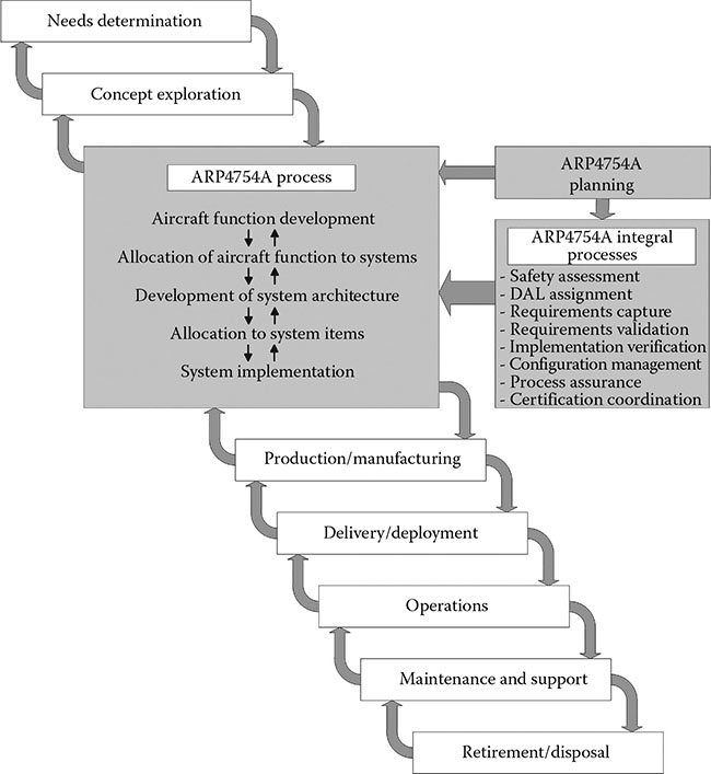
Figure 2.1 Overall system development process.
As will be discussed in Chapter 3, the safety assessment process runs parallel to the system development process. As the system progresses from high-level design to implementation, the safety aspects are evaluated to ensure that the system satisfies the required safety levels. While ARP4754A proposes a top-down approach, it recognizes that most systems are developed with an iterative and concurrent approach, using both top-down and bottom-up development strategies. Most aircraft are not made of systems developed from a clean sheet. Instead, aircraft and systems tend to be derivative projects that build upon existing functionality and products. Therefore, it is important that the overall development life cycle consider the baseline systems and develop a realistic life cycle that meets both the customer needs (documented in the form of requirements) and the safety objectives.
2.2 System Requirements
2.2.1 Importance of System Requirements
Chapter 3 will delve into the safety assessment process. For now, however, let us consider some important aspects of the system development. After living through numerous product developments, I have come to realize that many of the problems encountered in software development come from poorly defined system requirements and architecture. Software developers definitely have their problems (which will be discussed in future chapters), but many of the software issues are exacerbated by immature, incomplete, incorrect, ambiguous, and/or poorly defined system requirements. From my experience, most companies ought to spend more effort defining, validating, and verifying system requirements. This is mandatory, given the increase in system complexity and criticality. While there has been some improvement, much more is needed if we are to continue to develop safe, reliable, and dependable systems. The certification authorities also realize this need, and with the formal recognition of ARP4754A, they are increasing their attention on the system development processes—particularly, the requirements definition, validation, and implementation verification.
2.2.2 Types of System Requirements
ARP4754A recommends that the following types of requirements be developed [1]:
Safety requirements identify functions that either contribute to or directly affect the aircraft safety. The safety requirements are identified by the safety assessment process and include minimum performance constraints for both availability (continuity of function) and integrity (correctness of behavior). They should be uniquely identified and traced throughout the system life cycle.
Functional requirements specify functionality of the system to obtain desired performance. Functional requirements are usually a combination of customer requirements, operational requirements, performance requirements (for example, timing, speed, range, accuracy, and resolution), physical and installation requirements, maintainability requirements, interface requirements, and constraints. Functional requirements may also be safety requirements or have safety consequences that should be evaluated for impact on safety.
Other requirements include regulatory requirements and derived requirements. Derived requirements are typically the result of design decisions that are made as the system architecture matures. Since they may not trace to a higher level requirement, they need to be validated and assessed by the system safety process.
2.2.3 Characteristics of Good Requirements
Good requirements do not just happen. They require considerable effort, focus, and discipline. To write good requirements, it is important to understand the characteristics of such requirements. Requirements authors and reviewers should incorporate the following characteristics of good system requirements:
Atomic—each requirement should be a single requirement.
Complete—each requirement contains all of the necessary information to define the desired system functionality. Each requirement should be able to stand alone without further amplification.
Concise—each requirement should simply and clearly state what must be done and only what must be done. It should be easy to read and understand—even by nontechnical users of the system. In general, a textual requirement should not contain over 30–50 words. Requirements represented using graphics should also be concise.
Consistent—requirements should not contradict or duplicate other requirements. Consistent requirements also use the same terminology throughout the specification. Requirements are not the place to practice creative writing.
Correct—each requirement should be the right requirement for the system being defined. It should convey accurate information. This attribute is ensured by the requirement’s validation effort.
Implementation free—each requirement should state what is required without identifying how to implement it. In general, requirements should not specify design or implementation. However, there may be some exceptions, such as interface or derived system requirements.
Necessary—each requirement should state an essential capability, characteristic, or quality factor. If the requirement is removed, a deficiency should exist.
Traceable—each requirement should be uniquely identified and easily traceable through to lower level requirements, design, and testing.
Unambiguous—each requirement should only have one interpretation.
Verifiable—it should be possible to confirm the implementation of each requirement. Therefore, requirements should be quantifiable and include tolerances, as appropriate. Each requirement should be written such that it can be verified by review,* analysis, or test.† Except for rare cases, if the behavior cannot be observed during verification, the requirement should be rewritten. For example, negative requirements are generally not verifiable and require a rewrite.
Viable—each requirement should be able to be implemented, usable when implemented, and helpful to the overall system construction.
A requirements standard, requirements management plan, or best practices guide is recommended to provide guidance for requirements authors. Writing good requirements is not easy, even if you know for sure what you want to build. When I taught DO-178B classes for the FAA, we had a requirements writing exercise. The class was divided into teams and each team was given a LEGO® model. Each team was to write requirements for the model, tear it apart, put the pieces and the written requirements in a bag, and give it to another team to assemble using the requirements. At times, it was hilarious to see the end product, because it did not resemble the original model. Not everyone can write good requirements. In fact, from my experience, very few excel at this task. Good guidance, examples, and training based on the specific domain are invaluable. If graphical representations are used to explain the requirements, the standards should explain the rules and limitations of the graphics. For example, the standards may limit the number of symbols on a page, limit the number of pages for one graphic, limit the depth of a model, and provide detailed meaning for each symbol in the library (since various modeling tools have different interpretations for the symbols and developers have diverse levels of understanding). Chapters 5, 6, and 14 provide more discussion on requirements standards, software requirements development, and model-based development, respectively. These upcoming chapters focus on the software aspects of requirements but most of the suggestions also apply to systems requirements definition.
2.2.4 System Requirements Considerations
Requirements for safety-critical systems specify numerous functional ities. This section highlights some fundamental concepts to consider when developing systems requirements for software-intensive and safety-critical systems.*
2.2.4.1 Integrity and Availability Considerations
System requirements should address both integrity (correct functionality and operation) and availability (continuity of functionality). APR4754A defines integrity and availability as follows [1]:
Integrity: “Qualitative or quantitative attribute of a system or an item indicating that it can be relied upon to work correctly. It is sometimes expressed in terms of the probability of not meeting the work correctly criteria.”
Availability: “Qualitative or quantitative attribute that a system or item is in a functioning state at a given point in time. It is sometimes expressed in terms of the probability of the system (item) not providing its output(s) (i.e., unavailability).”
Loss of integrity results in incorrect operation (a malfunction) of the system. Examples include misleading data on the primary flight display, incorrect resolution advisory from a traffic collision and avoidance system (TCAS), or an autopilot hardover. In order to design for integrity, architectural mitigation is often required to prevent and/or neutralize faults. This may involve the use of redundancy, partitioning, monitoring, dissimilarity, or other mitigation strategies to prevent integrity faults or to protect from such faults. Additionally, in order to address integrity, fault detection and responses or fault containment is often applied and should be captured as systems requirements.
Many systems require protection from loss of availability. Availability differs from integrity in that the function operation must be continuous and/or recoverable under all foreseeable operating conditions (including normal and abnormal conditions). Key functionality must be available during and after random hardware faults, data faults, or software or hardware upset. Systems or functions requiring high availability generally require equipment with very high reliability and/or utilize redundancy. When redundant designs are used to ensure availability, they should be able to tolerate faults and/or detect and recover from faults quickly. Systems incorporating redundant designs typically have redundancy management and fault management requirements.
It should be noted that some design decisions may impact both integrity and availability. Both must be considered. For example, a system may need to mitigate integrity faults without compromising availability. The original version of ARP4754 noted the relationship between integrity and availability when considering the use of dissimilarity: “It should be noted that architectural dissimilarity impacts both integrity and availability. Since an increase in integrity may be associated with a reduction in availability, and viceversa, the specific application should be analyzed from both perspectives to ensure its suitability” [4].
2.2.4.2 Other System Requirements Considerations
In addition to integrity and availability concerns, there are other aspects to consider in the system specification, including:
Safety requirements, that is, requirements driven by the functional hazard assessment or subsequent safety analyses.
Fault tolerance effects on the systems, including the identification of fault regions. The Electronic Architecture and System Engineering for Integrated Safety Systems (EASIS) Consortium identifies a fault region as “a set of components whose internal disturbances are counted as exactly one fault, regardless of where the disturbances are located, how many occur, and how far they stretch within the fault regions” [5].
Graceful degradation (e.g., fail-safe mode), including the need for any containment regions. EASIS explains that “a containment region is the set of components which may be adversely affected by the respective malfunction. In other words: The containment region defines the border where fault propagation must stop” [5]. Examples include autopilot failure detection before the flight surfaces move or failed data flagged before the pilot responds.
Error detection, such as [5]:
Data checks—to examine data to determine if they are valid, in range, fresh, short-circuited, open-circuited, etc.
Comparison of redundant data—to compare the outputs of redundant sensors or processing units.
Checking for errors in processor and memory—for example, perform built-in tests, use watchdog timers, calculate checksums for read only memory (ROM) or flash memory, use built-in processor exceptions, perform memory checks, or test random access memory (RAM) read/write.
Communication monitoring—to perform checks on incoming messages in a distributed system, for example, check for message timeouts, message sequence counters, or checksums.
Error handling of the detected errors. Some examples of error handling are as follows [5]:
Turn off the function.
Enter a degraded mode.
Provide annunciation to the user.
Send a message to other systems that interact with the failed system.
Reset the system and return to the previous state.
Use other trustworthy data (when an input error is detected).
Timeout or shut down the channel or system, when an error is continuously detected.
Fault detection and handling, which covers how the system responds to hardware faults (such as, continuous or random response).
Fault avoidance, which may be handled by selecting high quality parts (with higher specified mean time between failures), protecting against environmental effects such as electromagnetic interference, identifying certain forbidden faults in the requirements, and/or architecturally eliminating vulnerabilities.
Requirements on the architecture or design (e.g., redundancy, comparison checks, voting schemes). While this somewhat blurs the boundary between requirements and design, it is important to identify anything that requires consideration during implementation. A commentary with the requirement is a common way to identify the design considerations without defining the design too soon.
Requirements on the manufacturing process. These requirements document the key characteristics of the hardware manufacturing and production processes.
Functional limitations. Any known or desired limitations of the system need to be specified in the requirements. For example, some functions may only be allowed during certain flight phases or range of use.
Critical functionality. These requirements are needed to prevent loss of critical functionality caused by a failure.
Partitioning or protection, to provide isolation from or containment of faults. Partitioning or protection might also be used to reduce validation and verification effort, since less critical functions require less validation and verification rigor. Partitioning and protection are discussed in Chapter 21.
Diversity, which may be used to avoid common faults in two or more items. Diversity examples include different designs, algorithms, tools (e.g., compilers), or technologies [5].
Redundancy, which may be used to achieve fault tolerance or to avoid a single point of failure. Redundant components include multiple processors, sensors, etc.
Timing-related requirements, to address concerns like cockpit response times, fault detections and responses, power-up times, restart times, etc.
Sequences, including initialization, cold start, warm start, and power down requirements.
Mode and state transitions, such as flight phases, engage and disengage decisions, mode selections, etc.
Environmental qualification levels, to reflect the environmental robustness needed. The levels depend on the system criticality, expected installation environment, and regulatory requirements. RTCA/ DO-160[ ]* explains the environmental qualification process for equipment installed on civil aircraft.
Test provisions, which may be needed to ensure the safety considerations are properly implemented. Examples include stimulus inputs, data recording, or other equipment interfaces to assist the testing effort.
Single and multiple event upset protections needed for some aircraft projects to protect the aircraft systems from radiation effects that occur at higher altitudes. Examples of common solutions include continuous built-in tests, error correction codes, voting schemes, and hardened hardware.
Reliability and maintainability considerations, especially to support safety analysis assumptions; for example, fault and associated data logging, initiated tests, and rigging.
Latency requirements to reduce the likelihood of faults remaining latent (hidden). Examples include alerts for fault identification and maintenance or built-in-test intervals.
User and human interface requirements, to ensure proper system use. Extensive certification guidance and standards exist to address human factors needs and to minimize operational issues.
Maintenance requirements or limitations, to ensure proper use and maintenance.
Safety monitoring requirements, when the system architecture requires safety monitors.
Security considerations, including protections such as encryptions, configuration and load checks, and interface barriers.
Future growth and flexibility needs, such as, timing and memory margins, minimized technology obsolescence, etc.
2.2.5 Requirements Assumptions
When developing the systems requirements and design, assumptions need to be documented. An assumption is a statement, principle, or premise that is not certain at the time the requirements are written [1]. There are numerous ways to document assumptions. Some commonly used methods are to: (1) include them as a commentary with the requirements or (2) create a separate document or database with links to the requirements (for instance, a separate requirements module or field). As the requirements are validated, the assumptions are also validated. Over time, the assumptions may become part of the requirements or design, rather than a separate category. For example, one may initially assume a certain maintenance period and document it as an assumption. During requirements validation, the maintenance period may be documented as a requirement (perhaps at a higher hierarchical level) so it is no longer just an assumption.
2.2.6 Allocation to Items
There are usually multiple hierarchical levels of systems requirements (such as, aircraft, system, and subsystem). The lower levels are decomposed from the higher levels, with more details (granularity) being defined at each lower level. The lowest level of system requirements is allocated to software or hardware for implementation. In ARP4754A, the software and hardware are called items. RTCA DO-178C is then applied to the software items and RTCA DO-254 (entitled Design Assurance Guidance for Airborne Electronic Hardware) to the electronic hardware items.*
2.3 System Requirements Validation and Verification
Not only are requirements developed, they are also validated and their implementation is verified. This section addresses both validation and verification.
2.3.1 Requirements Validation
Validation is the process of ensuring that requirements are correct and complete. It may include tracing, analyses, tests, reviews, modeling, and/or similarity claims [1]. Per ARP4754A, the higher the development assurance level (DAL), the more validation methods need to be applied. Ideally, system requirements allocated to software are validated before the software team begins formal implementation. Otherwise, the software may need to be rearchitected or rewritten once the valid systems requirements are identified. Unfortunately, it is often difficult to validate certain system requirements without some working software. Prototyping the software is a common way to support requirements validation, but as Chapter 6 discusses, prototyping should be handled carefully. System requirements that have not been fully validated prior to handing off to the software team need to be clearly identified so that stakeholders can manage the risk.
2.3.2 Implementation Verification
Verification is the process of ensuring that the system has been implemented as specified. It primarily involves requirements-based tests (RBTs); however, analyses, reviews or inspections, and demonstrations may also be used. As with requirements validation, ARP4754A requires more verification methods for functions with higher DALs. Verification is an ongoing activity; however, formal* verification of implementation occurs after the hardware and software have been developed and integrated.
2.3.3 Validation and Verification Recommendations
Below are some recommendations to effectively validate and verify system requirements.
Recommendation 1: Develop a validation and verification plan.† The validation and verification plan explains the processes, standards, environment, etc. to be used. The plan should explain roles and responsibilities (who will do what), ordering of events (when it will be done), and processes and standards (how it will be accomplished). The plan should also include the content specified by ARP4754A and be understandable and implementable by the engineers performing the validation and verification.
Recommendation 2: Train all validation and verification team members. All engineers responsible for performing validation and verification activities should be trained on the plans, standards, processes, techniques, expectations, etc. Most engineers do not intentionally fail; oftentimes, their shortcomings are because of lack of understanding. Training helps validation and verification engineers understand why certain tasks are important and how to carry them out effectively.
Recommendation 3: Apply appropriate methods. Validation methods focus on requirements correctness and completeness and include traceability, analysis, test, review, modeling, and similarity [1]. Verification methods focus on correctness of implementation to satisfy a given set of requirements; verification methods include reviews or inspections, analyses, tests, demonstrations, and service experience [1]. Rationale should be provided for areas where testing is not the selected method.
Recommendation 4: Develop checklists to be used by the teams. Validation and verification checklists help to ensure that engineers do not inadvertently forget something. Checklists do not replace the need to think but serve as memory joggers. The completed checklists also provide objective evidence that validation and verification efforts were performed.
Recommendation 5: Design the system and requirements to be testable. Testability is an important attribute of safety-critical systems and should be considered during the requirements capture and design. A case in point might be the implementation of test provisions that can detect errors during development and testing (e.g., bus babbler detector, partitioning violation monitor, slack checker, execution time monitor, out-of-bounds check, out-of-configuration check, built-in test, exception logs, monitors, etc.).
Recommendation 6: Develop and implement an integrated, cross-functional test philosophy. Involve as many disciplines as needed to get the right people involved at the right time, including software engineers.
Recommendation 7: Develop and run tests early and often. Proactive test development and execution is important. Early test efforts support both requirements validation and implementation verification. When writing the requirements, authors should think of how testing will be carried out. A couple of practices that help are: (1) to involve testers in requirements reviews and decisions and (2) to build an operational systems test station as soon as possible.
Recommendation 8: Plan test labs and stations early. The test facilities should be available as early as possible for multiple disciplines (e.g., software, systems, flight test, and hardware teams) to use. During planning phases, the number of users and the testing schedule should be considered to ensure adequate test facilities (number and capability). Since the customers may have some special needs or expectations, it is recommended to include them in the planning process as well.
Recommendation 9: Develop effective functional or acceptance tests and clearly identify pass or fail criteria. Since many engineers will need to use the test station and tests throughout the system development, it is important to spend time making the test environment effective, repeatable, and clear. It is ideal to automate as much as possible; however, there are normally at least a few tests that cannot be cost effectively automated.
Recommendation 10: Develop an integrated lab with accurate models for simulated inputs. The more complete the integration facility, the less the team relies on the aircraft or customer’s facility. The more realistic the simulated input the better. The goal is to sort out as many problems in the lab as possible to avoid the need to troubleshoot in the aircraft or customer’s facility.
Recommendation 11: Use validation and verification matrices. Matrices are a simple way to ensure that all requirements are validated and verified and to track the completion of the validation and verification effort.
Recommendation 12: Perform robustness testing. Robustness testing ensures that the system responds as expected when it receives unexpected or invalid input or when an abnormal combination or sequence of events occur. Robustness testing is often undervalued and underutilized at the systems level. When done effectively, it can mature the system and its underlying software before reaching the customer. For higher level systems (DAL A and B), ARP4754A requires that unintended functionality be considered during verification. Robustness testing provides confidence that the system will perform properly, even when events do not happen as expected.
Recommendation 13: Value the validation and verification effort. Both validation and verification are important for safety and certification. They are not just check marks or milestones on the master plan. Safety depends on how well validation and verification are done.
Recommendation 14: Keep the focus on safety. The team should be well-versed on the safety-related requirements and should spend a disproportionate amount of time on them during the validation and verification efforts. They should also recognize the signs of unintended safety compromise when testing other functions; for example, testers should not ignore excessive values, monitor flags, exceptions, or resets.
Recommendation 15: Flag issues as they arise. Issues rarely go away on their own, and frequently they get worse over time. If an issue is observed, it should not be ignored or hidden. Instead, it should be noted and evaluated. Once it is confirmed to be a valid issue, it should be documented for further investigation and resolution. An issues log (prior to baselining) and problem reports (after baselining) are typically used. Issues in the issues log that are not fixed prior to the baseline should be transferred to the problem reporting system to avoid being overlooked.
Recommendation 16: Do not sacrifice systems testing in order to compensate for schedule slips in other areas. It is a sad fact of life that verification is the last step in the chain and is under constant pressure to compensate for other slips in the schedule. This can lead to late discoveries, which are costly to fix and can severely stress the relationship with the customer.
Recommendation 17: Coordinate with software and hardware teams. Coordination between systems, software, and hardware tests can lead to earlier problem discovery (e.g., a software error might be found that also impacts systems) and optimized use of resources (e.g., there may be some systems tests that also verify software requirements and vice versa).
Recommendation 18: Gather meaningful metrics. Metrics can be used to track effectiveness, strengths, weaknesses, schedule, etc. Gathering the right metrics is important to effectively managing the validation and verification effort. Because validation and verification can consume half of the project budget* and is crucial to certification, it needs to be well-managed. Metrics can help by indicating where things are going well and where additional attention is needed.
2.4 Best Practices for Systems Engineers
Chapter 1 notes that well-qualified engineers are essential for building safe systems. Engineers are the masterminds behind the system. Without them, the system will not happen. Below are some suggested practices for the systems engineering team to implement in order to best use their talents and skills. These practices build upon the validation and verification recommendations in Section 2.3.3.
Best Practice 1: Plan ahead and put it in writing. Written plans are vital for successful certification. Develop plans for project management, safety, development, validation and verification, certification, etc. The plans should be practical, realistic, and visible for the people using them.
Best Practice 2: Plan for change. Develop an efficient change process for all levels of the system development and implementation. The change process should be clearly explained in the plans and should include a system-level change impact analysis process.
Best Practice 3: Foster a safety-focused culture. Educate the team on safety and their role in it. Safety should be embedded in organizational processes and part of team and management performance reviews. Additionally, it can be helpful to put up posters on safety, invite special speakers to inspire a safety consciousness, and remind engineers that their families’ safety may depend on their actions. Safety should color all decisions and actions at all levels of the enterprise.
Best Practice 4: Document best practices. There is great value in capturing recommended practices and augmenting them with actual examples, based on years of experience. Once documented, the best practices should become mandatory reading for all new engineers or team members. Oftentimes, the best practices evolve into the company standards and processes.
Best Practice 5: Develop a top-level, enterprise-wide design philosophy. Organization-level practices such as, fail-safe approaches, maintenance boundaries, message approaches (such as alerts, warnings, color, and occurrence), etc. should be documented. Once documented, teams should be trained on the philosophy so that their daily decisions are consistent with the company’s preferences.
Best Practice 6: Ensure the system architecture addresses known hazards from the aircraft and system hazard assessments. Oftentimes, multiple architectures are proposed and evaluated to determine which one best meets safety expectations, certification requirements, and customer needs.
Best Practice 7: Develop the system architecture with functional breakdowns early. Organize the architecture into logical groups as soon as possible, and use it to drive plans, hazard assessments, requirements, standards, program tracking, etc.
Best Practice 8: Perform an early safety assessment. The safety assessment determines the viability of the system architecture. In the early stages it does not need to be a full preliminary system safety assessment (PSSA); instead, it is used to confirm the concepts.
Best Practice 9: Capture explicit safety requirements. Safety requirements need to be documented so that they can be flowed down to software and hardware teams. Normally, safety requirements are identified with a shall (to show the mandatory nature) and a safety attribute.
Best Practice 10: Explain the rationale behind the requirements. It is helpful to explain where each requirement came from and how it relates to other requirements, standards, guidance, etc.
Best Practice 11: Document all assumptions and justification for derived requirements. Assumptions and justifications should be documented as the requirements are written. Do not put it off for later, since by that time the thought process may be forgotten.
Best Practice 12: Develop a proof-of-concept or prototype. A proof-of-concept or prototype helps mature the requirements and design. However, teams should be willing to throw away the prototype. Prototyping is a means to an end, not the end. Trying to upgrade a prototype to meet certification standards usually takes more time than starting again. Prototyping is discussed more in Chapter 6.
Best Practice 13: Involve hardware and software engineers in the requirements development process. The earlier hardware and software engineers understand the system, the more informed their design decisions will be, and the faster and more effectively they can implement the system.
Best Practice 14: Do not assume the requirements are right until they have been validated. It is best to keep an open mind and look for ways to improve and optimize requirements until validation. Despite some marketing claims, the customer is not always right. If something does not seem right or is unclear, raise it to the customer early.
Best Practice 15: Validate requirements as early as possible. Requirements validation is an ongoing process, but it is important to start it early using the right engineers with the right experience. Section 2.3.3 provides more suggestions for the validation effort.
Best Practice 16: Orchestrate early and frequent evaluations. Early evaluations by the customer, human factors personnel, pilots, maintenance crews, systems and aircraft integrators, certification authorities, etc. help to ensure that all stakeholders’ expectations are met.
Best Practice 17: Update requirements based on input. Use input from hardware, software, safety engineers, and other stakeholders to improve and mature the requirements.
Best Practice 18: Hold early and ongoing informal reviews by peers. Peer reviews help to find issues early and ensure consistency among team members.
Best Practice 19: Use a requirements management tool. Since requirements are foundational to safe and successful implementation, it is important to manage them well. A requirements management tool can help to effectively manage requirements, by allowing faster and higher quality implementation of system requirements. Some manufacturers use a Word/textual document to house their requirements; however, unless carefully handled, such an approach can lead to requirements that are not uniquely or clearly identified and difficulties can arise in tracing to or from the requirements. This can force the software and hardware developers to interpret and make assumptions. Sometimes the interpretations and assumptions are correct but too frequently they are not. If used properly, a requirements management tool can help avoid some of these challenges. However, care must be taken not to lose the overall context and relationship of the requirements when they are captured in the tool.
Best Practice 20: Document and enforce company-wide standards and templates for systems requirements and design. Requirements standards and templates should promote the qualities that were discussed earlier in this chapter. Design standards and templates should address these kinds of topics: design rationale, constraints, allocation, limitations, safety paths, initialization, modes and controls, margins, modeling standards, etc.
Best Practice 21: Use graphical representations as appropriate. Graphics (e.g., user interfaces, display graphics, and control systems models) help to effectively communicate concepts; however, they should be supported with appropriate text.
Best Practice 22: Conduct formal reviews. Formal reviews are performed at key transition points throughout the system development. Chapter 6 discusses the peer review process.
Best Practice 23: Provide training to the systems team(s). Ongoing training is important for the systems engineers. Suggested training topics include: requirements writing, company standards, domain or context (for instance, aircraft design or avionics), architecture, safety attributes, safety techniques, safety philosophy, and best practices. Training should include concrete examples.
2.5 Software’s Relationship to the System
Software is part of the system implementation. The system architecture and requirements drive the software development. Therefore, it is critical for systems, software, safety, and hardware engineers to communicate. The earlier and more frequently that communication occurs throughout the development process, the fewer problems will occur. The systems, safety, software, and hardware leads should develop a close working relationship throughout the project. I like to compare the four-disciplined team to the four legs of a chair. Without one of the legs, the chair is severely limited. Without two legs, it is useless. Communication failures among the four disciplines lead to unnecessary challenges—potentially causing wrong interpretation and implementation of system requirements, missed dependencies, inadequate tests, and wasted time and money. During a recent assessment of test data for a safety-critical avionics application, our team noticed that some of the software requirements were not tested. The software test lead said that the systems test team was exercising those requirements. When we approached the system test lead, he responded: “We aren’t testing those, because the software guys are.” Failure to communicate and to share test matrices led to a situation where no one was testing some of the system functions. Simple communication was all that was needed to avoid this problem.
Below are some suggestions to foster an integrated relationship between systems, safety, software, and hardware teams.
Colocate the teams.
Develop a core group involving each discipline’s key stakeholders. This group provides leadership, makes key decisions, maintains consistency, evaluates and approves changes, etc.
Work together as a core group to identify and document the overall design philosophy. Then share that philosophy with the entire team.
Coordinate handoffs and transitions between the disciplines (i.e., ensure that data are mature enough for the next team to use).
Encourage an open and backlash-free environment to identify, escalate, and resolve issues.
Do not be afraid to involve the customer and certification authority when needed. Getting clarification on uncertain issues can prevent wrong decisions.
Encourage extracurricular activities to improve team dynamics (go to lunch, dinners, parties, off-site meetings, sporting events, etc., together).
Share lessons learned frequently and throughout the program.
Promote cross-training between teams in key discipline areas (e.g., arrange for weekly or monthly presentations).
Have safety representatives provide training on the system safety assessment results, so that everyone is familiar with the safety drivers.
Use incremental and iterative modeling; this helps to build up the system and encourage frequent coordination.
Encourage teams to build safety and quality into the product. It is next to impossible to add them in as afterthoughts.
Track metrics that encourage teams to consider and assist each other (these might include measuring software functions successfully integrated on the hardware—not just the completion of hardware or software).
References
1. SAE ARP4754A, Guidelines for Development of Civil Aircraft and Systems (Warrendale, PA: SAE Aerospace, December 2010).
2. ISO/IEC 15288, Systems and Software Engineering—System Life Cycle Processes, 2nd edn. (Geneva, Switzerland: International Standard, February 2008).
3. ISO/IEC 12207, Systems and Software Engineering—Software Life Cycle Processes, 2nd edn. (Geneva, Switzerland: International Standard, February 2008).
4. SAE ARP4754, Certification Considerations for Highly-Integrated or Complex Aircraft Systems (Warrendale, PA: SAE Aerospace, November 1996).
5. Electronic Architecture and System Engineering for Integrated Safety Systems (EASIS) Consortium, Guidelines for Establishing Dependability Requirements and Performing Hazard Analysis, Deliverable D3.2 Part 1 (Version 2.0, November 2006).
*Reviews are also called inspections in some literature.
†Tests are also called demonstrations in some literature. Tests tend to be the preferred method of verification for most certification authorities.
*Please note that this section is merely an overview and does not exhaustively cover the subject.
*[] indicates the latest revision or the revision required by the certification basis.
*At this time, it is not completely clear what guidance applies to the hardware items where DO-254 is not applied (such as, non-electronic hardware or simple hardware). This area of ambiguity is expected to be cleared up in the future when DO-254 is updated to DO-254A. At this point in time ARP4754A, DO-254, or additional certification authority guidance (for example, FAA Order 8110.105, European Aviation Safety Agency Certification Memo CM-SWCEH-001, or project-specific Issue Papers) are used to cover the ambiguous areas.
*Formal verification is used for certification credit.
†The validation and verification planning may be in separate plans.
*Numerous project managers indicate that over half of their budget and time are spent on validation and verification.