3 Software in the Context of the System Safety Assessment
Acronym
| ASA | aircraft safety assessment |
| CCA | common cause analysis |
| CMA | common mode analysis |
| CNS/ATM | communication, navigation, surveillance, and air traffic management |
| FDAL | functional development assurance level |
| FHA | functional hazard assessment |
| HIRF | high intensity radiated fields |
| IDAL | item development assurance level |
| PASA | preliminary aircraft safety assessment |
| PRA | particular risk analysis |
| PSSA | preliminary system safety assessment |
| SFHA | system functional hazard assessment |
| SSA | system safety assessment |
| ZSA | zonal safety analysis |
3.1 Overview of the Aircraft and System Safety Assessment Process
As discussed in Chapter 2, safety is assessed in parallel with the aircraft and system development. This chapter provides an overview of the civil aviation safety assessment process, as well as an explanation of how software fits into the system and safety framework. Figure 3.1 shows the iterative nature of the system and safety development; as the system develops, the safety aspects are identified and addressed by the design. SAE’s ARP4761, entitled Guidelines and Methods for Conducting the Safety Assessment Process on Civil Airborne Systems and Equipment, provides a detailed description of the expectations for civil aviation.* Other domains use similar approaches (e.g., Military-Standard-882, the U.S. Department of Defense standard for system safety). The main elements of the ARP4761 safety assessment process will now be described.
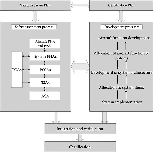
Figure 3.1 Overview of the system and safety assessment processes.
3.1.1 Safety Program Plan
The Safety Program Plan development is typically the first task performed in the overall assessment of the aircraft safety. The plan identifies how the aircraft safety will be ensured, how safety-related requirements will be identified, what safety standards will be applied, what data will be produced, what methods will be employed, who will perform the tasks, key milestones, and how the various tasks will be coordinated in order to ensure correctness, completeness, and consistency. ARP4574A appendix B provides a sample Safety Program Plan, which may be used as a template to start an aircraftspecific safety plan. If used, the ARP4754A appendix B example will need to be tailored to fit the specific needs and organizational structure of the stakeholders involved in the specific project [1]. ARP4761 provides specific techniques for performing analyses identified in the Safety Program Plan, along with examples and sample checklists. In addition to the aircraft-level Safety Program Plan, many systems will also have a system-level safety plan for their individual system or product. These lower level safety plans may be referenced from the aircraft-level Safety Program Plan. Either the Safety Program Plan or the aircraft-level Certification Plan typically shows the relationship between the various aircraft-level and system-level plans and data.
3.1.2 Functional Hazard Assessment
The functional hazard assessment (FHA) is developed once the basic aircraft functionality and conceptual design are documented. The FHA identifies and classifies failure conditions associated with aircraft functions and combinations of functions. The effects of the failure conditions on the aircraft are assessed against the regulations and supporting guidance that establish the safety requirements and objectives for the aircraft. In the aviation world, the required safety objectives vary by aircraft type (e.g., transport category airplanes [Part 25], small airplanes [Part 23], small rotorcraft [Part 27], transport category rotorcraft [Part 29], engines [Part 33], or propellers [Part 35]).* The large transport category aircraft tend to have the most rigid requirements due to the overall risk to human life. Small aircraft have some alleviation, depending on the aircraft size and its area of operation. Table 3.1 shows the severity classifications along with the failure condition effects and required probabilities for a large transport category aircraft† (assurance levels are also shown and will be discussed in Section 3.2). Other aircraft types, engines, and propellers have similar classification; however, the probability levels for Part 23 aircraft may be lower, depending on the aircraft class. The FHA is a living document that is updated as additional aircraft functionality and failure conditions are identified during aircraft development. The final FHA identifies the functions, failure conditions, phases of operation for each function, effects of the function failure, classification of the failure, and verification methods.
Developing an FHA is an intense process. It includes the following efforts for the entire aircraft: (1) analyzing possible scenarios in which a failure could occur, (2) assessing the results if it did occur, and (3) determining if changes are needed. It uses input from past projects, accidents, and flight experience. It involves experienced engineers, pilots, human factors experts, safety personnel, and regulatory authorities. While people are usually good at understanding the consequences of a single hazard, it is the combinations of multiple realistic failures that make the FHA particularly challenging. Each aircraft has its own peculiarities, but historical evidence (e.g., accidents and incidents) of similar platforms plays a role.
Table 3.1 Failure Condition Severity, Probabilities, and Levels
| Severity Classification | Potential Failure Condition Effect | Likelihood of Occurrence | Exposure Per Flight Hour (Part 25) | Assurance Level |
| Catastrophic | Failure conditions, which would result in multiple fatalities, usually with the loss of the airplane | Extremely improbable | 1E−9 | A |
| Hazardous/ Severe major | Failure conditions, which would reduce the capability of the airplane or the ability of the flight crew to cope with adverse operating conditions to the extent that there would be
|
Extremely remote | 1E−7 | B |
| Major | Failure conditions, which would reduce the capability of the airplane or the ability of the crew to cope with adverse operating conditions to the extent that there would be a significant reduction in safety margins or functional capabilities, a significant increase in crew workload or in conditions impairing crew efficiency, discomfort to the flight crew, or physical distress to passengers or cabin crew, possibly including injuries | Remote | 1E−5 | C |
| Minor | Failure conditions, which would not significantly reduce airplane safety and which involve crew actions that are well within their capabilities. Minor failure conditions may include a slight reduction in safety margins or functional capabilities; a slight increase in crew workload, such as routine flight plan changes; or some physical discomfort to passengers or cabin crew | Reasonably probable | 1E−3 | D |
| No safety effect | Failure conditions that would have no effect on safety; e.g., failure conditions that would not affect the operational capability of the airplane or increase crew workload | Probable | 1.0 | E |
3.1.3 System Functional Hazard Assessment
The system functional hazard assessment (SFHA) is similar to the FHA, except it goes into more detail for each of the systems on the aircraft.* It analyzes system architecture to identify and classify failure conditions and combinations of failure conditions. This may lead to an update of the FHA and the overall aircraft or system design.
3.1.4 Preliminary Aircraft Safety Assessment
The preliminary aircraft safety assessment (PASA) “is a systematic examination of a proposed architecture(s) to determine how failures could cause the Failure Conditions identified by the FHA” [1]. The PASA is the highest level preliminary safety analysis and is developed from the aircraft FHA. The PASA is typically performed by the aircraft manufacturer and considers combinations of systems and interfaces between them. The PASA inputs include the aircraft-level and system-level FHAs, preliminary common cause analyses (CCAs), and proposed system architectures and interfaces. The PASA may identify updates to the FHA and SFHA and will typically generate lower level safety requirements.
3.1.5 Preliminary System Safety Assessment
Like the PASA, the preliminary system safety assessment (PSSA) is a topdown examination of how failures can lead to functional hazards identified in the FHA and SFHAs. While the PASA focuses on the aircraft architecture and integration of systems, the PSSA focuses on the proposed architecture of a specific system, subsystem, or product. Each major aircraft system will have a PSSA. There may be multiple hierarchical levels of PSSAs for systems that have multiple subsystems.
The PSSAs are typically performed by the system developers and go into detail for each system on the aircraft. As the aircraft systems mature, the PSSAs provide feedback to the PASA.
The PASA and PSSA processes may lead to additional protection or architectural mitigation (e.g., monitoring, partitioning, redundancy, or built-intest). The PASA and PSSA outputs serve as feedback or input to the FHA and SFHAs, system architecture, and system requirements. The PASA and PSSA also impact software and hardware requirements.
Overall, the PASA and PSSAs are intended to show that the proposed design will meet the safety requirements of the regulations and the FHA and SFHAs. The PASA and PSSA serve as inputs to the as-built final aircraft safety assessment (ASA) and system safety assessments (SSAs). The PASA and PSSA are the assessments that typically provide the development assurance levels for the system (functional development assurance levels— FDALs) and the software and electronic hardware (item development assurance levels—IDALs).
3.1.6 Common Cause Analysis
The CCA evaluates system architecture and aircraft design to deter mine sensitivity to any common cause events. This helps to ensure that (1) independence is achieved where needed and (2) any dependencies are acceptable to support the required safety level. The CCA verifies that the independence needed for safety and regulatory compliance exists, or that the lack of independence is acceptable. ARP4754A explains that the CCA “establishes and verifies physical and functional separation, isolation and independence requirements between systems and items and verifies that these requirements have been met” [1]. The output of the CCA is input to the PASA and/or PSSA and the ASA and/or SSA. Three separate analyses are typically performed to evaluate common cause; each is explained in the following [2]:
A particular risk analysis (PRA) evaluates “events or influences which are outside the system(s) and items(s) concerned, but which may violate failure independence claims” [2]. ARP4761 provides several examples of events or influences external to the aircraft or external to the system or item being evaluated. An example of something external to the aircraft is bird strike. Some business jets install their avionics in the aircraft nose bay, which is susceptible to bird strikes at lower altitudes. Therefore, redundant systems (such as navigation and communication) are physically located on opposite sides of the nose bay, preventing the common cause. Other examples of risks external to the aircraft include ice, high intensity radiated fields (HIRF), or lightning [2]. An example of something external to the system is an engine rotor burst that might occur, cutting through the hull of the aircraft. In order to reduce the susceptibility to such an event, physical separation of electrical power, flight controls, hydraulic systems, etc. is typically required. Other risks external to the system include fire, bulkhead rupture, leaking fluids, security tampering, and tire tread separation [2].
A zonal safety analysis (ZSA) is performed for each zone on the aircraft. Example zones include nose bay, cockpit, cabin, left wing, right wing, tail cone, fuel tanks, cargo bay, and avionics bay. A ZSA ensures that the installation “meets the safety requirements with respect to basic installation, interference between systems, or maintenance errors” [1]. The ZSA is carried out for each identified zone of the aircraft and includes design/installation guidelines, examination to ensure conformance to the guidelines, and inspection to identify any interference (based on the failure modes and effects analysis and summary).
The common mode analysis (CMA) considers any kind of common effect during development, implementation, test, manufacturing, installation, maintenance, or crew operation that may lead to a common mode failure. CMAs are performed at multiple hierarchical levels of the aircraft development—all the way from the top aircraft level down to the individual circuit cards. CMAs verify that events ANDed together in the fault tree analysis, dependence diagrams, and/or Markov analysis are truly independent [2]. This analysis has an impact on software development because it considers common modes such as software development errors, systems requirements errors, functions and their monitors, and interfaces. The CMA helps determine what development assurance levels are assigned for the system, software, and hardware. Development assurance is explained in Section 3.2.
3.1.7 Aircraft and System Safety Assessments
The ASA and SSAs verify that the implemented aircraft and system design meets the safety requirements defined in the FHA, SFHAs, PASA, and PSSAs. The ASA and SSAs are performed on the as-built, implemented design, whereas the PASA and PSSAs are based on the proposed design. The ASA and SSAs are the final evidence that the aircraft meets the regulatory safety requirements.
As with the PASA and PSSAs, the ASA is usually performed by the aircraft manufacturer, and the SSAs are performed by the systems developers. The ASA considers combinations and integration of systems and is closely coordinated with the multiple SSAs.
3.2 Development Assurance
In complex and highly integrated electronic systems with software and/ or programmable hardware, it is not feasible to test all combinations of inputs and outputs to assign a probability of failure. This limitation, combined with the fact that computer programs do not deteriorate or fail over time like physical components, leads to the need for a concept called development assurance. Development assurance is used to ensure confidence in the process used to develop the system and its items. Development assurance is “all of those planned and systematic actions used to substantiate, at an adequate level of confidence, that errors in requirements, design and implementation have been identified and corrected such that the system satisfies the applicable certification basis” [1]. Development assurance assumes that a more rigorous process is more likely to identify and remove errors before the product is delivered than a less rigorous process. The concept of development assurance was initially introduced to address software; however, it also applies to other domains where exhaustive testing is infeasible. Table 3.2 identifies domains where development assurance is applied in civil aviation, along with the industry documents that provide the guidance for each domain.*
Development assurance levels are established by the safety assessment process, based on the potential safety impact of the system. ARP4754A defines development assurance level as “the measure of rigor applied to the development process to limit, to a level acceptable for safety, the likelihood of errors occurring during the development process of aircraft/ system functions and items that have an adverse safety effect if they are exposed in service” [1]. For most aircraft and engines, the assurance levels shown in Table 3.1 apply.* The probabilities for each category shown in Table 3.1 are used for hardware items where reliability is applicable.
Table 3.2 Development Assurance Documents for Civil Aviation

3.2.1 Development Assurance Levels
ARP4754A identifies two phases of system development: function development phase and item development phase. The function development phase includes the development, validation, verification, configuration management, process assurance, and certification coordination for the system. At the lowest level, system requirements are allocated to software or hardware, referred to as items. The software or hardware items have their own development phases. ARP4754A guidance applies to the system development phase; DO-178B/C applies to the software development phase; and DO-254 applies to the electronic hardware development phase.
The traditional V-model illustrated in Figure 3.2 shows the function and item development phases. At the function level, an FDAL is assigned based on the system’s potential impact on safety. The software and electronic hardware are assigned IDALs.
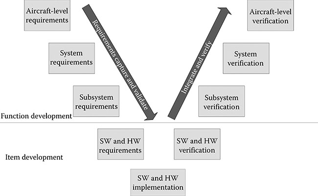
Figure 3.2 The V-model for system development.
The FDAL determines the amount of rigor required at the system level (e.g., the amount of requirements reviews, testing, and independence). The IDAL determines the amount of rigor required for the specific item’s development (software or electronic hardware development). Depending on the architecture, the IDAL may be lower than the FDAL. ARP4754A explains the FDAL and IDAL assignment approach. The FDAL determines what objectives of ARP4754A apply at the system level. Likewise, the IDALs determine what DO-178C (or its supplements) objectives apply for software or DO-254 objectives for electronic hardware.
It is important to note that FDAL and IDAL are assigned at the system level and as a result of the safety assessment process. The initial IDAL assignment should be completed before the DO-178C or DO-254 planning activities conclude. The IDAL is called a software level in DO-178C (and its supplements) and throughout the remainder of this book. We will examine the DO-178C objectives in Part III (Chapters 4 through 12).
3.3 How Does Software Fit into the Safety Process?
The role of software has increased over the last 20 years. As software has become more pervasive, the system and safety processes have also evolved. The traditional analog and mechanical system failure analysis and reliability techniques do not work on software because of its complexity and uniqueness. This section examines (1) software’s uniqueness that drives the need for the development assurance process and (2) how software fits into the system and safety process.
3.3.1 Software’s Uniqueness
Software, unlike hardware, does not follow the laws of physics—it does not wear out, break under known conditions, or fail in predictable ways. Some other unique characteristics are as follows [3]:
Programs can be complex and difficult to understand, even if they are short.
Software tends to improve with time because latent errors are discovered and corrected.
Correcting an error in one area can introduce another error, which can be in a seemingly unrelated area.
Software can interface with dozens or even hundreds of other software modules.
Unlike hardware, software does not provide forewarning when it fails. Latent software errors can remain invisible for years and then suddenly appear.
Software can be easily changed (which is why it’s called soft-ware).
Finding an error in software can be long and laborious, especially if not handled proactively.
At this point in time, it is not possible to prove if the software is perfect or judge how close to perfect it is. In fact, one might go as far as to say that all software has some errors in it because it is developed by imperfect humans. The reliability techniques applied to hardware simply do not apply to software. If we relied on traditional hardware reliability approaches, only very simple software would be allowed on the aircraft.
3.3.2 Software Development Assurance
Because of the inability to accurately apply reliability models to software, the concept of development assurance is applied by most safety-focused industries, including the aviation industry. Development assurance is defined in Section 3.2. The goal of development assurance is to apply rigorous processes to the development process in order to prevent, identify, and remove errors. The more critical the functionality, the more development and verification activities are applied. For the aviation industry, DO-178B, and now DO-178C, identify five software levels based on the safety process (DO-178 and DO-178A had three levels). Table 3.1 shows the relationship between the software levels and the failure condition categories. Level A software is the most rigorous and applies to software functionality that could cause or contribute to a catastrophic aircraft-level event. For level A, all of the objectives of DO-178C apply.* Level E software has no safety implications; therefore, none of the DO-178C objectives are required.
Table 3.3 demonstrates how the development and verification rigor and the number of objectives increase as the software level goes up. As the level increases, more activities and more independence are required. Each of the objectives summarized in Table 3.3 are explored in Part III. For now, it’s important to understand that the higher the software level, the more verification is performed, the more independence is required, and the more errors are identified and removed.
3.3.3 Other Views
It is virtually impossible to scientifically prove the claims of the development assurance approach. Also, a good process does not necessarily mean a robust, safe product. As I often say in jest: “Not all level A software is created equally.” One can have a great process and still produce buggy software; often due to use of inexperienced personnel or bad systems requirements. Likewise, a team can have a substandard process and produce robust and dependable software; primarily because of the use of highly skilled and experienced engineers. DO-178C assumes the use of qualified and welltrained people; however, it is difficult to measure the adequacy of people. Some authorities examine resumés and training history to ensure that qualified and properly trained personnel are used.
For companies without a strong safety foundation, it can be tempting to choose a software level without understanding why the level was needed. Divorcing the software development process from the system requirements and safety drivers can lead to major safety issues. Because of this, DO-178C, ARP4754A, and ARP4761 have attempted to improve the guidance to addressing implementation of software in the system. However, the temptation still exists and must be monitored.
Because development assurance can’t be scientifically supported, there are some who question and even denounce the use of development assurance. Most of these critics promote the use of safety and reliability models at the software level. They extend the SSA process to include the software and minimize the reliance on development assurance. Such efforts employ safety use cases and models to demonstrate that the system is reliable under a given set of conditions expected to be encountered. Extensive effort and skill are required to develop the scenarios and exercise the system under those scenarios. The safety focus is beneficial to ensure that the software design supports the system safety. However, to date, software reliability modeling techniques are still limited and controversial.
Table 3.3 Summary of DO-178C Objectives
| Level | Obj Count | Obj w/ Ind | Summary of Objectives |
| E | 0 | 0 | No activities required |
| D | 26 | 2 | Plans (five plans) High-level requirements developed Architecture developed Executable object code developed Parameter data item files developed (if needed) and verified for correctness and completeness Some review and analysis of high-level requirements Only review or analyze architecture if using partitioning Normal and robustness testing of high-level requirements Requirements coverage of high-level requirements Testing to verify target compatibility Configuration management Quality assurance (compliance to plans and conformity review) Accomplishment summary and configuration index |
| C | 62 | 5 | Level D activities Development standards (three standards) Low-level requirements developed Trace data developed Source code developed Additional review and analysis of high-level requirements Some review and analysis of low-level requirements Some review and analysis of architecture Review and analysis of some source code Verification of parameter data item files Normal and robustness testing of low-level requirements Requirements coverage of low-level requirements Review test procedures Review test results Statement coverage analysis Data and control coupling analysis Additional quality assurance (review plans and standards, compliance to standards, and transition criteria) |
| B | 69 | 18 | Level C and D activities Additional review and analysis of high-level requirements (target compatibility) Additional review and analysis of low-level requirements (target compatibility and verifiability) Additional review and analysis of architecture (target compatibility and verifiability) Additional review and analysis of source code (verifiability) Decision coverage |
| A | 71 | 30 | Level B, C, and D activities Modified condition/decision coverage analysis Source to object code traceability verification |
Obj, objectives; Ind, independence.
3.3.4 Some Suggestions for Addressing Software in the System Safety Process
As was previously noted, safety is a system attribute—not a software attribute. Sound systems, safety, hardware, and software engineering are necessary for safe system implementation. Here are some suggestions for improving the tie between the disciplines:
Assign safety attributes to the software requirements that specifically support safety protections, in order to identify which software requirements are most crucial to safety. This also helps to ensure that the safety implications of changes are fully considered.
Involve the system and safety engineers in the review of software requirements and architectures.
Coordinate derived software requirements with the safety team as soon as they are identified to ensure that there are no safety impacts. Include rationale in derived requirements, so that they can be understood, evaluated for safety, and maintained.
Colocate system, safety, hardware, and software teams.
Perform PSSA early in order to identify software levels and clearly identify what system functions have safety impact; that is, make it clear what drives the software level assignment or what mitigations (protections) are needed in the software.
Provide a summary of the PSSA to the entire software team to ensure that they understand the rationale for the software level and the impacts of their work on safety.
Consider carrying the safety assessment down into the software to support the overall safety assessment process. This is particularly beneficial when protection (e.g., partitioning or monitoring) is implemented in the software.
Train the software team in the basics of system development, the SSA process, development assurance level assignment, common techniques used for developing safety-critical systems, and what they should be aware of for their system.
Use experienced teams. If junior engineers are used (we all have to start somewhere), pair them with experienced engineers.
Develop a safety-focused culture. If top-level management supports safety and walks the talk, it makes an incredible difference in how it is viewed and implemented down in the trenches.
References
1. SAE ARP4754A, Guidelines for Development of Civil Aircraft and Systems (Warrendale, PA: SAE Aerospace, December 2010).
2. SAE ARP4761, Guidelines and Methods for Conducting the Safety Assessment Process on Civil Airborne Systems and Equipment (Warrendale, PA: SAE Aerospace, December 1996).
3. J. P. Bowen and M. G. Hinchey, Ten commandments of formal methods… Ten years later, IEEE Computer, January 2006, 40–48.
*At this time ARP4761 is being updated. Once it is available, ARP4761A should be used instead of ARP4761.
*Each Part is from Title 14 of the U.S. Code of Federal Regulations.
†Covered by Part 25 of Title 14 of the U.S. Code of Federal Regulations.
*There is typically an SFHA for each system on the aircraft.
*The equivalent EUROCAE document numbers are also included.
*For some small aircraft (Part 23), the levels are lower. See Federal Aviation Administration Advisory Circular 23. 1309-1[ ] (where “[ ]” represents the latest revision).