14 DO-331 and Model-Based Development and Verification
Acronym
| EASA | European Aviation Safety Agency |
| EUROCAE | European Organization for Civil Aviation Equipment |
| FAA | Federal Aviation Administration |
| HLR | high-level requirement |
| LLR | low-level requirement |
| SC-205 | Special Committee #205 |
| SCADE | standard for the development of critical embedded display software |
| WG-71 | Working Group #71 |
14.1 Introduction
The DO-331 glossary defines a model as follows:
An abstract representation of a given set of aspects of a system that is used for analysis, verification, simulation, code generation, or any combination thereof. A model should be unambiguous, regardless of its level of abstraction.
Note 1: If the representation is a diagram that is ambiguous in its interpretation, this is not considered to be a model.
Note 2: The ‘given set of aspects of a system’ may contain all aspects of the system or only a subset [1].
Models may enter the requirements hierarchy as system requirements, software requirements, and/or software design. Systems and software engineers have used models for years to graphically represent controls. However, the use of qualified modeling tools that automatically generate code, and in some cases even automatically generate test vectors, is a relatively recent paradigm shift for the aviation software community. The Airbus A380 used model-based development extensively for the following systems: flight controls, autopilot, flight warning, cockpit display, fuel management, landing gear, braking, steering, anti-ice, and electrical load management [2]. Other aircraft manufacturers are also modeling requirements for control systems. Figures 14.1 and 14.2 provide an example of a simple model. The same model is shown in Simulink® (Figure 14.1) and SCADE (standard for the development of critical embedded display software) (Figure 14.2).
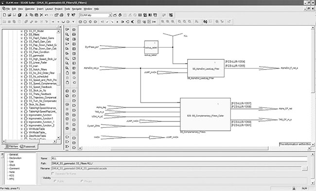
Figure 14.1 Example of model in Simulink®. (Courtesy of Embraer, São Paulo, Brazil.)

Figure 14.2 Example of model in SCADE. (Courtesy of Embraer, São Paulo, Brazil.)
With such a shift there is potential for incredible benefits, but the benefits are not without some risks and growing pains. This chapter examines both the advantages and the disadvantages of model-based development from a certification and safety perspective. Additionally, a brief overview of DO-331, Model-Based Development and Verification Supplement to DO-178C and DO-278A, is provided.
14.2 Potential Benefits of Model-Based Development and Verification
There are a number of potential benefits to model-based development and verification. The ability to reap these benefits depends on the implementation details and may not all be realized.
Potential Benefit 1: V life cycle to Y life cycle. One of the main motivators of model-based development is the ability to go from the traditional V life cycle to a Y life cycle, with the potential to reduce development time, cost, and possibly even human error. By putting focus on the system requirements and utilizing automation, the life cycle may shorten. Some estimates show a 20% reduction when using an unqualified code generator and up to 50% when using a qualified code generator [3]. Figures 14.3 and 14.4 illustrate the progression from V to Y life cycle.
There are a number of ways to introduce the models into the product life cycle. They may be generated at the system level, the software requirements level, and/or the software design level. Most companies attempt to have a platform independent level model that abstracts the model from the platform, making it more portable. The platform-specific details may be represented in a lower level model.
Potential Benefit 2: More focus on requirements. As Chapter 6 noted, requirements errors are often the root cause of software-related in-service problems. Additionally, the later a requirement error is found, the more expensive it is to fix. When a model represents the requirements, it has the potential to present a clearer view of the system or software functionality during requirements capture than textual requirements. When automation is used to implement the model (such as qualified autocode generators), it allows development teams to concentrate on the graphical representation of the requirements, rather than focusing on implementation details. If properly executed, this can promote higher quality requirements and earlier detection of requirements errors.
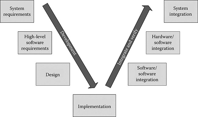
Figure 14.3 Traditional V life cycle.

Figure 14.4 Y Life cycle using model-based development and verification.
Potential Benefit 3: Earlier verification. When qualified model-to-code tools are used, the focus shifts from the code to the model (i.e., less time is spent on code implementation details and more on the model itself). Use of model simulation and/or automatic test case generators promotes early verification, enabling earlier maturity of requirements and detection of errors. Figures 14.3 and 14.4 illustrate the differences between traditional and model-based development. Since verification often consumes about 50%–70% of the software resources, detecting errors earlier and reducing the manual verification effort can be a benefit to the project budget and schedule [4].
Potential Benefit 4: Reduction of unnecessary redundancy and inconsistencies. Traditional software development uses three levels of requirements: (1) system requirements allocated to software, (2) software high-level requirements (HLRs), and (3) software low-level requirements (LLRs). Depending on the requirements capture approach, there can be significant redundancy between these levels, which may lead to inconsistencies when changes are made. The use of qualified modeling tools has the potential to reduce these redundancies and inconsistencies. However, when there are multiple levels of models, there can also be a fair amount of redundancy and potential inconsistencies. Hence, like the other benefits noted, it really depends on the approach taken.
Potential Benefit 5: Improved requirements understandability. Some tools produce models that are easier to understand than textual requirements. Therefore, they may promote greater accuracy, consistency, and completeness. Models can be more intuitive than textual requirements, allowing easier detection of errors and gaps in planned behavior [2]. However, not all modeling tools generate easy-to-understand models and some of the models generated are quite confusing. Modeling tools should be selected with care. A good modeling standard is also essential to ensure that all developers are using the model notations, symbols, and tools properly.
Potential Benefit 6: Improved interaction with customers. As discussed in Chapter 6, customer input is crucial to capturing the right requirements. Due to the more intuitive nature of models, they can be useful to gain input from customers and systems engineers. This can increase early coordination between customers, systems, and software teams, which improves the overall quality and accuracy of the requirements.
Potential Benefit 7: Growing tool support. The capability and quality of modelbased development and verification tools is growing. There are still not many qualified code generators available, but there are some. There are also tools available to verify the output of the code generators. When confidence in one tool cannot fully be realized, it might be possible to use two different tool paths to boost the confidence. For some of the more critical systems (e.g., flight controls), this might be a recommended approach even if you do have confidence in the tools, as it helps to reduce the concern of a common design error.
Potential Benefit 8: Evolving formal methods support. Interestingly, there appears to be a convergence of modeling technology, tool support, and formal methods which can significantly increase the benefits of model-based development and verification. When a modeling tool suite, including the code generator, is formally verified for correctness, the tool can be relied upon to perform its intended functionality. Without formal verification, there is always the uneasy feeling that the modeling tool or underlying code generator might insert an error given some corner-case scenario. However, formal methods can provide confidence in the model-to-code tool suite by verifying the entire input and output space. See Chapter 16 for more information on formal methods.
14.3 Potential Risks of Model-Based Development and Verification
As with any technology, there are a number of potential challenges when using model-based development and verification. Several of them are noted here.
Potential Risk 1: Loss of multiple requirements reviews. When models are implemented using automatic code generation, some of the traditional scrutiny of the requirements may be lost, particularly if the model is introduced at the systems level. In the traditional software development, there are reviews of the systems requirements, software requirements, design, and code. Additionally, as each level of requirements is analyzed to generate the lower level, issues are identified and resolved. For example, someone implementing the code might find an inconsistency with the requirements. Mats Heimdahl refers to this as collateral validation. He notes: “Experienced professionals designing, developing code, or defining test-cases provide informal validation of the software system” [4]. As these engineers examine the data, they notice errors and can ensure appropriate corrective action is taken. However, when the model is pushed to a higher level and implementation is handled by tools, this collateral validation is reduced or lost altogether [4].
Potential Risk 2: Expansion of systems engineering role. In the aviation world, at least at this point in history, software engineers have been more committed to process than systems engineers. DO-178B, and now DO-178C, has enforced this. Systems engineers, however, are really just now beginning to implement development assurance practices. Therefore, if the model is controlled by systems engineering, there is concern about the quality of the model to meet the DO-178C and DO-330 expectations. For example, it may not be common for systems engineers to ensure compliance to standards, perform documented reviews of their artifacts, or test all requirements. Systems engineers may also be unfamiliar with the concepts of requirements coverage, robustness testing, model coverage analysis, etc. To overcome this issue, it is advisable to supplement the systems engineer ing team with experienced software engineers. Both systems and software engineers benefit from such an arrangement.
Potential Risk 3: Traceability difficulties. Even when requirements are graphically presented as models, they still need to trace up to the higher level requirements and down to the lower level requirements or code. The traces to the higher level and to the lower level must be bidirectional. Some modeling tools do not support traceability well. The trace between textual requirements and model-based requirements can be particularly challenging.
Potential Risk 4: Difficulties with test completeness. Depending on the modeling approach and the test team’s experience, it may be difficult to ensure that the requirements presented in the form of a model are fully verified. Complex models can be particularly challenging to completely verify. Detailed testing guidelines are needed to ensure that the requirements-based tests fully verify the model. Additionally, model complexity also needs to be controlled in order to ensure the testability of the models.
Potential Risk 5: Simulation credit controversy. One of the drivers for modelbased development and verification is the desire to utilize simulation tools to identify errors as early as possible. However, when companies try to take formal verification credit for the simulation (which is not executed on the target computer), it can become controversial. DO-331 attempts to clarify what is expected and allowed for simulation, but prior to DO-331, it has been a case-by-case debate with the certification authorities. Even with DO-331, the credit requested for simulation will require close coordination with the certification authorities.*
Potential Risk 6: Models often mix what and how. Because models frequently include details about the implementation, it can become difficult to discern what the model does. Basically, the design and requirements get mixed. As noted in Chapter 6, this is often a problem in traditional development as well; however, models particularly lend themselves to this dilemma. To prevent this situation, DO-331 requires a level of requirements above the model. Hopefully, such guidance will encourage developers to identify what the model is supposed to do. Unfortunately, I’ve seen some rather weak requirements above the model. For example, I once saw a 98-page model that had one requirement above it. The requirement essentially said: “You shall have a model.” It’s rather difficult to test that!
Potential Risk 7: Separating specification models from design models challenges. As will be discussed shortly, DO-331 provides guidance for specification models and design models. The guidance states that the models cannot be combined.
In reality, it may prove challenging to distinguish between specification and design models, particularly for already existing models. Most existing models combine what (requirements) and how (design) to some degree. Additionally, most modeling techniques encourage the inclusion of design detail (e.g., equations and algorithms). Separating specification models and design models will require a significant paradigm shift for most organizations.
Potential Risk 8: Model validation challenges. Specification models, particularly at the system level, need to be validated for correctness and completeness. Without this, the implementation of the model is of little value. Oftentimes, processes for model validation are limited. DO-331 attempts to address this by requiring model coverage analysis (which is discussed later in this chapter) in addition to traceability to the requirements above the model.
Potential Risk 9: Blurring the systems and software roles. Depending on where the model is introduced, the systems team may be more involved in lower level details than they are accustomed, and the software team may be more involved in higher level details than is traditional. If handled correctly, the closer connection between systems engineers and software engineers can be beneficial. However, without proper consideration there may be unnecessary overlap or large gaps in the process.
Potential Risk 10: Challenges combining traditional and model-based development. Most model-based development projects have some traditional (nonmodel) requirements and design in addition to the models. Likewise, there is typically some manual code required, even when a code generator is used. The combination of traditional and model-based development must be carefully defined to ensure consistency and completeness. Likewise, both DO-178C and DO-331 will need to be used (DO-178C for traditional and DO-331 for models); this requires some extra thought, coordination, and planning. The plans should clearly define the development, verification, and integration of both traditional and model-based techniques.
Potential Risk 11: Inconsistent model interpretation. If the modeling notation is not well defined and carefully implemented, it can lead to inconsistent interpretations of the model. Thorough modeling standards and adherence to them should address this issue.
Potential Risk 12: Model maintenance. Without adequate documentation, the models may not be maintainable. Not too long ago, I was involved in a flight control project. The engineer who created the model left the company. Other key engineers also left the company. The team left to finish the certification effort had no idea what the model did or why it did it. All that existed was the model itself; there were no higher level requirements, assumptions, justification, or rationale. It was unclear why certain decisions were made and why some model elements were included. It was a nightmare to validate the correctness and completeness of the model and to verify its implementation.
The moral of the story is: maintainable models require thorough documentation. Just as it’s important to put comments in the code (see Chapter 8), it is crucial to explain and justify modeling decisions. Section 14.4 (Difference #3) explains this concept further.
Potential Risk 13: Automatic test generation controversy. Some modeling tools not only automatically generate code, but also automatically generate tests against the model. This is beneficial to informally verify and build confidence in the model. However, when a project attempts to use the automatically generated tests for certification credit, it causes several concerns. If the model is wrong, the error may not be caught. In traditional software testing, the human test authors often find issues with the requirements and weaknesses in the system (see Chapter 9). Machine generated tests may not be as effective. Model coverage analysis may help alleviate some of this concern, if implemented properly. However, in addition to model coverage analysis, manually generated tests to consider integration, safety requirements, key functionality, challenging functions, and robustness may be needed to supplement the automatically generated tests. When using automatically generated tests one must also ensure adequate independence; for higher software levels, the test generator and the code generator must be independently developed.
Potential Risk 14: Tool instability. Because of the reliance of model-based development and verification on tools, any instability in the tools can be problematic. Immature tools may change frequently, which can lead to the need to regenerate and/or re-verify models. I recently heard of an issue found in a modeling tool that has been used by multiple aircraft manufacturers and their suppliers. Each tool user had to evaluate the impact of the newly discovered issue on their product. The ripple effect of a tool problem can be quite significant in the safetycritical domain. It is recommended that if you are using qualified tools to support model-based development and verification, you ensure that they are mature and rigorous enough for the task at hand. An independent assessment of the tool and its supporting data may be beneficial to ferret out its suitability and maturity.
Potential Risk 15: Modeling limitations. Not every system is suitable to modeling. Model-based development and verification will not be the right approach for every project or organization. Despite some claims, it is not a silver bullet.
14.4 Overview of DO-331
DO-331, entitled Model-Based Development and Verification Supplement to DO-178C and DO-278A, was the most challenging supplement developed by RTCA Special Committee #205 (SC-205) and European Organization for Civil Aviation Equipment (EUROCAE) Working Group #71 (WG-71). It was also the last document approved by the committee and may be the least mature. There are a variety of approaches to modeling and opinions on how to best implement models in a safety-critical domain. The DO-331 guidance attempts to provide flexibility for model implementation, while at the same time ensuring that the software generated using the model performs its intended function and only its intended function. If used properly, the supplement helps to address several of the concerns mentioned earlier in this chapter.
Like the other supplements, DO-331 uses the DO-178C outline and modifies, replaces, or adds objectives, activities, and guidance to DO-178C, as needed.
The DO-331 definition of model is included earlier in Section 14.1. DO-331 recognizes that a model may come into the software life cycle as system requirements, software requirements, and/or software design and that there may be multiple levels of model abstraction. Regardless of the level that a model enters the software life cycle, there must be requirements above and external to the model to explain details and constraints to enable the modelbased development and verification activities.
DO-331 section MB.1.6.2 defines two types of models: (1) specification model and (2) design model. The description of each is provided in the following [1]:*
A Specification Model represents high-level requirements that provide an abstract representation of functional, performance, interface, or safety characteristics of software components. The Specification Model should express these characteristics unambiguously to support an understanding of the software functionality. It should only contain detail that contributes to this understanding and does not prescribe a specific software implementation or architecture except for exceptional cases of justified design constraints. Specification Models do not define software design details such as internal data structures, internal data flow, or internal control flow. Therefore, a Specification Model may express high-level requirements but neither low-level requirements nor software architecture.
A Design Model prescribes software component internal data structures, data flow, and/or control flow. A Design Model includes low-level requirements and/or architecture. In particular, when a model expresses software design data, regardless of other content, it should be classified as a Design Model. This includes models used to produce code.
There are two important things to note about these model types. First, a model cannot be classified as both specification model and design model. Second, since DO-330 requires that there must be requirements above the model, there will always be at least two levels of requirements when using models [1].
DO-331 retains most of the guidance of DO-178C, but adds some modelspecific information. In general, most of the guidance in DO-178C related to HLRs applies to specification models and the guidance for software design applies to design models. The most significant differences between DO-330 and DO-178C are summarized in the following. These are the areas where DO-331 modifies or clarifies (i.e., supplements) DO-178C for application to model-based development and verification.
Difference 1: Model planning. During the planning phase, the plans should explain the use of modeling and how it fits into the software life cycle. Plans should explain what software life cycle data are represented by each model, what model standards will be used, and the intended verification approach. If simulation will be used for credit, the plans should explicitly detail the approach and what credit is sought. The planning phase should also define the model simulation environment, including methods, tools, procedures, and operating environment if simulation is used to formally support verification. Depending how the simulator is used, it may need to be qualified; the rationale for why qualification is or is not needed should be included in the plans. Chapter 13 explains the tool qualification criteria and approach.
If there are both traditional textual requirements and design elements used in addition to the models, it should be explained in the plans. In this situation, the plans need to explain how both the DO-178C and DO-331 objectives will be satisfied. There are various ways to accomplish this. One way is to include both DO-178C and DO-331 objectives in the PSAC (perhaps as an appendix) to show how both sets of objectives will be satisfied.
Difference 2: Model standards. Each type of model used must have standards to explain the modeling techniques, constraints, instructions, etc. DO-331 section MB.11.23 explains that there should be a model standard for each type of model and each standard includes the following kinds of information, as a minimum [1]:
Explanation and justification for the methods and tools to be used.
Identification of the modeling language to be utilized and any language syntax, semantics, features, and limitations.
Style guidelines and complexity restrictions that allow the modeling approach and its implementation to be unambiguous, deterministic, and compliant with DO-331 objectives. Complexity restrictions are particularly important. Typically, the depth of the model (nesting levels), number of architectural layers, and number of elements per diagram need to be restricted.
Constraints to ensure proper use of the modeling tools and supporting libraries.
Methods to identify requirements, establish bidirectional traceability between requirements layers, identify derived requirements, document justification for all derived requirements, and identify any model element that is not a software requirement or design (such as comments).
The model standards are the guide for the developers to enable them to produce high quality and compliant models. Clear guidelines and realistic examples are beneficial.
Difference 3: Supporting model elements. DO-331 explains that model elements that do not contribute to or realize the requirements or design implementation must be clearly identified. DO-331 adds three objectives to address this. All three objectives are in DO-331 Annex MB.A Table MB.A-2 and are listed in the following [1]:
Objective MB8: “Specification Model elements that do not contribute to implementation or realization of any high-level requirement are identified.”
Objective MB9: “Design Model elements that do not contribute to implementation or realization of any software architecture are identified.”
Objective MB10:”Design Model elements that do not contribute to implementation or realization of any low-level requirement are identified.”
Difference 4: Model element libraries. Libraries are used extensively in most modeling tools. For example, the symbols used to graphically illustrate a model come from a symbol library. Each library element that can be used in a model must be assured to the proper software level per DO-178C. Basically, the library elements need plans, development standards, requirements, design, code, verification cases and procedures, etc., just like any other safety-critical software. If there are elements in the library that do not have the appropriate level of assurance, they should not be used. It is preferable to remove them from the library altogether to avoid inadvertent use. However, if that is not feasible, there should be explicit standards to prohibit unassured element use and reviews to ensure the standards are followed. Additionally, the modeling standards need to provide guidelines to properly use the library elements.
Difference 5: Model coverage analysis for design models. The DO-331 glossary defines model coverage analysis as:
An analysis that determines which requirements expressed by the Design Model were not exercised by verification based on the requirements from which the Design Model was developed. The purpose of this analysis is to support the detection of unintended function in the Design Model, where coverage of the requirements from which the model was developed has been achieved by the verification cases [1].
Model coverage analysis is not the same as structural coverage analysis. DO-331 section MB.6.7 explains the recommended model coverage analysis activities and criteria, as well as resolution activities if any coverage issues are noted. Interestingly, DO-331 section MB.6.7 is referenced as an activity and not an objective in the DO-331 Annex MB.A Table MB.A-4 (i.e., the MB.6.7 reference is in the Activity column—not the Objective column). Objective 4 states: “Test coverage of low-level requirements is achieved.” Model coverage analysis is only needed for design models. Its inclusion in DO-331 was somewhat controversial, which is why it was included as an activity and not an objective. Even though it is only listed as an activity in DO-331 Table MB.A-4 and not an objective, most certification authorities will expect it to be performed. They will likely allow alternate approaches to be used but will still need evidence that the design model has been fully verified to the same level of rigor that model coverage analysis provides.
Difference 6: Model simulation. The DO-331 glossary defines model simulation and model simulator as follows [1]:
Model simulation: The activity of exercising the behavior of a model using a model simulator.
Model simulator: A device, computer program or system that enables the execution of a model to demonstrate its behavior in support of verification and/or validation.
Note: The model simulator may or may not be executing code that is representative of the target code.
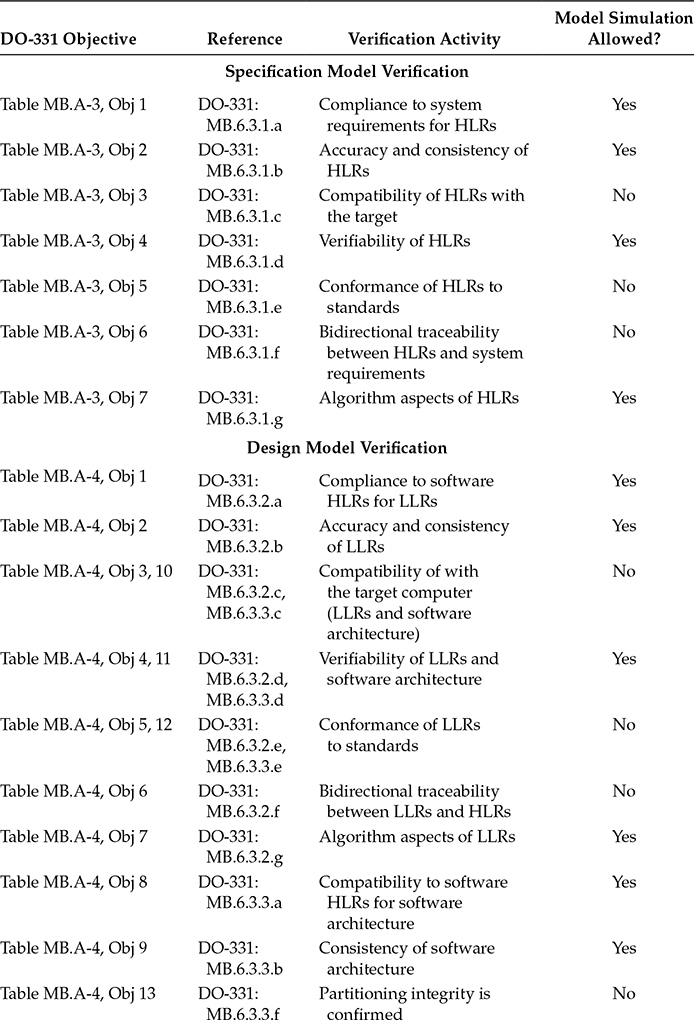
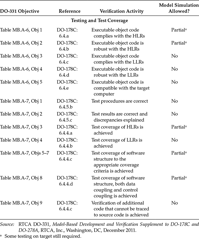
DO-331 section MB.6.8 provides specific guidance on model simulation. Model simulation may be used to satisfy some of the DO-331 verification objectives. Table 14.1 summarizes DO-331 objectives that may or may not be satisfied using model simulation. As a model may represent HLRs, LLRs, or software architecture, the objectives in Table 14.1 apply to the applicable representation of the model.
If simulation cases and procedures are used for formal verification credit, the simulation cases and procedures need to be verified for correctness and the simulation results need to be reviewed and any results discrepancies explained. DO-331 adds new objectives to Annex MB.A Tables MB.A-3 (objectives MB8–MB10), MB.A-4 (objectives MB14–MB16), and MB.A-7 (objectives MB10–MB12) to address the verification of the simulations cases, procedures, and results. The three objectives are the same but are repeated in the three Annex tables since they apply to different phases of the software life cycle [1]:
“Simulation cases are correct.” (Table MB.A-3 objective MB8, Table MB.A-4 objective MB14, and Table MB.A-7 objective MB10)
“Simulation procedures are correct.” (Table MB.A-3 objective MB9, Table MB.A-4 objective MB15, and Table MB.A-7 objective MB11)
“Simulation results are correct and discrepancies explained.” (Table MB.A-3 objective MB10, Table MB.A-4 objective MB16, and Table MB.A-7 objective MB12)
Table 14.1 Summary of Objectives Related to Model Simulation
14.5 Certification Authorities Recognition of DO-331
Prior to the publication of DO-331, the international certification authorities have used project-specific issue papers (or equivalent) to identify model-based development and verification issues that need to be addressed.* It is anticipated that these issue papers (or equivalent) will no longer be needed when DO-331 is used as the means of compliance. As experience with DO-331 is gained, there may be some additional certification authority guidelines in the future to clarify model-based development and verification issues.
Of all the DO-178C supplements, DO-331 will likely be the most difficult to apply, especially when trying to apply the guidance to existing models. Some specific challenges are as follows:
Developing a complete set of requirements above the model, particularly when the model is outside the software life cycle.
Clarifying the scope of DO-331 in the systems domain.
Separating specification model and design model.
Performing model coverage analysis.
Performing bidirectional tracing between the model elements and the higher and lower levels.
Integrating the new guidance into existing processes.
Using model simulation for certification credit.
Automatically generating tests against the models.
References
1. RTCA DO-331, Model-Based Development and Verification Supplement to DO-178C and DO-278A (Washington, DC: RTCA, Inc., December 2011).
2. S. P. Miller, Proving the shalls: Requirements, proofs, and model-based development, Federal Aviation Administration 2005 Software & Complex Electronic Hardware Conference (Norfolk, VA, 2005).
3. B. Dion, Efficient development of airborne software using model-based development, 2004 FAA Software Tools Forum (Daytona, FL, May 2004).
4. M. Heimdahl, Safety and software intensive systems: Challenges old and new, Future of Software Engineering Conference (Minneapolis, MN, 2007).
*As experience with DO-330 is gained, this is an area where additional guidance will likely be developed by the certification authorities.
*Italics added for clarification.
*For example, the European Aviation Safety Agency’s (EASA) certification memo CM-SWCEH-002 (“Software Aspects of Certification”) dated August 11, 2011, includes a section on model-based development (section 23). This certification memo is called out in EASA certification review items which are the EASA equivalent of Federal Aviation Administration (FAA) issue papers.