
Chapter 11. Programming the 3270 Presentation Logic Component
In this chapter:
There are three steps that are necessary to build up this component:
Part way through the chapter, we’ll have a digression and introduce a little background about symbolic description maps.
First, a recap about the purpose of the component that we are going to write. This program is the first one executed when the NACT transaction is entered on a 3270 terminal. Apart from local printing, all of the code in the presentation logic has been placed in a single program. This is because the application is not big enough to justify multiple programs. NACT01, the name of our program, displays the menu screen, which prompts the user for request input, and ends when it returns control to CICS. In returning, it specifies that the same transaction (NACT) is to be executed when the next input is received from this terminal. NACT01 will be invoked repeatedly to process the input from the menu. A typical piece of code that does this is:
X-RETURN-COM-AREA SECTION.
*
* This routine saves data and ends the task
*
* This section is performed from the following sections -
* B-GET-MENU-DATA
* DB-SEND-DETAIL-WITH MESSAGE
* DE-SEND-MENU-WITH-MESSAGE
* U-SEND-EMPTY-MENU
* W-LINK-FOR-BROWSE
*
 X-010.
   EXEC CICS RETURN TRANSID(EIBTRNID)
             COMMAREA(DFHCOMMAREA)
   END-EXEC

 END-X-RETURN-COM-AREA.
  EXIT.
Once input is received from the user, the program performs the necessary validation, invokes the appropriate back-end process (in this case NACT02), or schedules a print action, depending on the user request. It displays the data required, accepts and validates account data, and displays appropriate messages to keep the user informed of the results of their actions.
There are some important points to note about the implementation of this logic, which are considerations when using 3270 terminals:
If a message is returned as the result some part of your program’s logic, the whole screen is refreshed and the message is displayed.
The Browse request logic must be adapted to the fact that there may be more matches found on file than can be displayed at one time. This actually leads to a change in the specification of the browse back-end (NACT05) program to limit the output and to accept a resume browse request.
The NACT transaction expects the program to supply the data in a form suitable for printing, when it performs the print scheduling function.
The program implements the standard error handling approach designed for the application. It uses CICS facilities to identify the error handling program (NACT04) as the one to be invoked in the event of an abend occurring as well as using it to process any unexpected errors that may arise.
Defining Screens with Basic Mapping Support (BMS)
At the beginning of the first program (NACT01), one of the first things you need to do is to write a formatted screen to the input terminal. This requires the use of CICS terminal input/output services and the most common tool that is used is Basic Mapping Support (BMS). This is probably the easiest way to set up the 3270 interface. That said, let’s now plunge in and try to code our sample application. If you are new to BMS, you may find some of this a little tedious, but once you have coded a few maps, the coding discipline becomes quite understandable.
First, some background information. CICS supports a wide variety of terminals, from ATMs to retail store systems. In this book, however, we cover only the most common CICS terminals—those of the IBM 3270 system. The sample in this book is relatively simple, so there are only features that do not depend on a particular terminal access method, and we only cover formatted output. For detailed information, see the CICS Application Programming Guide on the CD-ROM.
What Is BMS and What Does It Do?
BMS simplifies your programming job, keeping your code largely independent of any changes in your network of terminals and of any changes in the terminal types. It’s probably easiest to define what BMS does by examining the menu screen that is part of our initial program; see Figure 11-1. It all looks quite straightforward, even if there is a lot of detail.
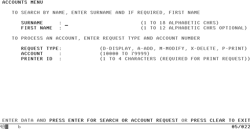
You define this screen with BMS macros, which are a form of System/390 Assembler language. When you’ve defined the whole map, put some job control language (JCL) around it and assemble it. You assemble it twice, in fact. One of the assemblies produces the physical map. This gets stored in one of the execution-time libraries, just like a program, and CICS uses it when it executes a program using this particular screen. However, this physical map does not contain any executable code—the physical map is stored in a program library to enable it to be loaded and unloaded like code.
The physical map contains the information BMS needs to:
Build the screen, with all the titles and labels in their proper places and all the proper attributes for the various fields.
Merge the variable data from your program in the proper places on the screen when the screen is sent to the terminal.
Extract the variable data for your program when the screen is received.
The information is in an encoded form comprehensible only to BMS; fortunately we never need to examine this ourselves.
The other assembly produces a structure which we call the symbolic description map. This structure defines all of the variable fields (the ones you might read or write in your program), so that you can refer to them by name. The data structure gets placed in a library along with similar copy/include structures like file record layouts, and you simply introduce it into your program in the normal way.
Tip
If your company uses a software tool to create maps, like Screen Definition Facility II (SDF II), you can go directly to Copying the Map Structure into a Program.
Defining a Menu Map Using BMS Macros
To show you how this works, let’s go ahead and define the menu map. There are three map-definition macros that you need: DFHMDF to generate a map definition for a field, DFHMDI to generate a map definition, and DFHMSD to generate a map set definition. Don’t be put off by the syntax; it’s really quite simple when you get used to it. We’ll go from the inside out, starting with the individual fields, but be aware that the program object used by BMS is called a MAPSET, which contains one or more maps which, in turn, contain one or more fields.
The DFHMDF macro: generate a map definition for a field
For each field in a map, you need one DFHMDF macro, which looks like this:
fldname DFHMDF POS=(line,column),LENGTH=number,
               INITIAL='text',OCCURS=number,
               ATTRB=(attr1,attr2,....)
The items in this macro are:
- fldname
This is the name of the field, as it is used in the program. Name every field that you intend to read or write in your program, but don’t name any field that’s constant, other labels, or the stopper fields that define the end of the input field in this screen. For example, see the DFHMDF macro with LENGTH=1 after the FNAMED definition in Example 11-1. The name must begin with a letter, contain only letters and numbers, and can be up to 30 characters long.
- DFHMDF
The DFHMDF macro defines a field within a map defined by the DFHMDI macro. A map contains one or more fields.
- POS=(line, column)
This is the position on the screen where the field should appear. (In fact, it’s the position relative to the beginning of the map. For the purposes of this book, however, screen and map position are the same.) Remember that a field starts with its attribute byte, so if you code POS=(1,1), the attribute byte for that field is on line 1 in column 1 (the top left corner), and the actual data starts in column 2. For the type of maps in this book, you need this parameter for every field.
- LENGTH=number
This specifies the length (1–256 bytes) of the field or group of fields. This length should be the maximum length required for application program data to be entered into the field; it should not include the one-byte attribute indicator appended to the field by CICS for use in subsequent processing. The length of each individual subfield within a group must not exceed 256 bytes.
If the LENGTH specification in a DFHMDF macro causes the map-defined boundary on the same line to be exceeded, the field on the output screen is continued by wrapping.
- INITIAL=‘text’
This specifies constant or default data for an output field. INITIAL is used to specify data in character form; XINIT is used to specify data in hexadecimal form. For fields with the detectable (DET) attribute, initial data that begins with one of the following characters: ? > & blank that should be supplied.
- GRPNAME=‘name’
This is the name used to generate symbolic storage defintions and to combine specific fields under one group name. For example, a group of fields such as a continuous string of characters, (04 11 2000) can be displayed on the screen as 04:11:2000 where the additional characters can be inserted from the map.
- OCCURS=‘number’
This specifies that the indicated number of entries for the field are to be generated in a map, and that the map definition is to be generated in such a way that the fields are addressable as entries in a matrix or an array. This permits several data fields to be addressed by the same name (subscripted) without generating a unique name for each field.
OCCURS and GRPNAME are mutually exclusive; OCCURS cannot be used when fields have been defined under a group name. If this operand is omitted, a value of OCCURS=1 is assumed.
- ATTRB=(attr1,attr2,…)
These are the attributes of the field, and there are a number of different characteristics you can specify. The first is the display intensity of the field, and your choices are:
- NORM, BRT, DRK
NORM normal display intensity.
BRT specifies that a high-intensity display of the field is required. Because of the 3270 attribute character bit assignments, a field specified as BRT is also potentially detectable. However, for the field to be recognized as detectable by BMS, DET must also be specified.
DRK specifies that the field is nonprint/nondisplay. DRK cannot be specified if DET is specified.
- ASKIP, PROT, UNPROT, NUM
ASKIP (autoskip) is the default and specifies that data cannot be keyed into the field and causes the cursor to skip over the field.
PROT specifies that data cannot be keyed into the field. If data is to be copied from one device to another attached to the same 3270 control unit, the first position (address 0) in the buffer of the device to be copied from must not contain an attribute byte for a protected field. Therefore, when preparing maps for 3270s, ensure that the first map of any page does not contain a protected field starting at position 0.
UNPROT specifies that data can be keyed into the field.
NUM ensures that the data entry keyboard is set to numeric shift for this field unless the operator presses the alpha-shift key, and prevents entry of nonnumeric data if the Keyboard Numeric Lock feature is installed.
- FSET, IC, DET
FSET specifies that the modified data tag (MDT) for this field should be set when the field is sent to a terminal. Specification of FSET causes the 3270 to treat the field as though it has been modified. On a subsequent read from the terminal, this field is read back, whether or not it has been modified. The MDT remains set until the field is rewritten without ATTRB=FSET, or until an output mapping request causes the MDT to be reset.
Insert Cursor IC specifies that the cursor is to be placed in the first position of the field. The IC attribute for the last field for which it is specified in a map is the one that takes effect. If not specified for any fields in a map, the default location is zero. Specifying IC with ASKIP or PROT causes the cursor to be placed in an unkeyable field.
DET specifies that the field is potentially detectable. The first character of a 3270 detectable field must be one of the following: ? > & blank. If ? or > the field is a selection field; if
&orblank, the field is an attention field. A field for which BRT is specified is potentially detectable to the 3270, because of the 3270 attribute character bit assignments, but is not recognized as such by BMS unless DET is also specified.- DET and DRK are mutually exclusive
You don’t need the ATTRB parameter. If you omit it, the field will be ASKIP and NORM, with no FSET and no IC specified. If you specify either the protection or the intensity characteristics, however, it will be clearer if you specify both, because the specification of one can change the default for the other.
The DFHMDI macro: generate BMS map definition
At the beginning of each map there is a macro, DFHMDI, which provides the control information:
mapname DFHMDI SIZE=(line,column),
               CTRL=(ctrl1,ctrl2,...)
The items in this macro are:
- mapname
This is the name (1–7 characters) of the map.
- DFHMDI
This is the macro identifier, also required. It shows that you’re starting a new map.
- SIZE=(line, column)
This parameter gives the size of the map. You need it for the type of maps we’re using. BMS allows you to build a screen using several maps, and this parameter becomes important when you are doing that. In this book, however, we’ll keep to the simpler situation where there’s only one map per screen. In this case, there’s no point in using a size other than the screen capacity.
- CTRL=(ctrl1,ctrl2,…)
This defines characteristics of IBM 3270 terminals. This parameter shows the screen and keyboard control information that you want sent along with a map. Use of any of the control options in the SEND MAP command overrides all control options in the DFHMDI macro, which in turn overrides all control options in the DFHMSD macro.
This must be specified if the printer is to be started; if omitted, the data is sent to the printer buffer but is not printed. This operand is ignored if the mapset is used with 3270 displays without the Printer Adapter feature.
- LENGTH
This indicates the line length on the printer; length can be specified as L40, L64, L80, or HONEOM. L40, L64, and L80 force a new line after 40, 64, or 80 characters, respectively. HONEOM causes the default printer line length to be used. If this option is omitted, BMS sets the line length from the terminal definition.
- FREEKB
This causes the keyboard to be unlocked after the map is written. If FREEKB is not specified, the keyboard remains locked; data entry from the keyboard is inhibited until this status is changed.
- ALARM
This activates the 3270 audible alarm. For non-3270 VTAM terminals, it sets the alarm flag in the command section of the data stream (FMH) passed to the device.
- FRSET
This specifies that the modified data tags (MDTs) of all fields currently in the 3270 buffer are to be reset to a not-modified condition (that is, field reset) before map data is written to the buffer. This allows the DFHMDF macro with the ATTRB operand to control the final status of any fields written or rewritten in response to a BMS command.
The DFHMSD macro: generate BMS map set definition
You can put several maps together into a map set. In fact, all maps (even a single map) must form a map set. For efficiency reasons, it’s a good idea to put related maps that are generally used in the same transactions in the same map set. All the maps in a map set get assembled together, and they’re loaded together at execution time as well. So far you have defined only one map but our sample uses more than one map; see Map Definitions for the Sample Application.
When you’ve defined all the maps for a set, you put another macro in front of all the others to define the map set. This is the DFHMSD macro:
mapset DFHMSD TYPE=type,MODE=mode,LANG=COBOL,
              STORAGE=AUTO,TIOAPFX=YES,
              CTRL=(ctrl1,ctrl2,...)
The items in this macro are:
- mapset
This is the name of the map set. You use it when you issue a CICS command to read or write one of the maps in the set; it’s required. Like a field name, it must start with a letter, consist of only letters and numbers, and be no more than seven characters long.
Because this name goes into the list of installed program definitions, make sure your system programmer (or whoever maintains these lists) knows what the name is, and that neither of you changes it without telling the other. It is the load module name.
- DFHMSD
This is the macro identifier, also required. It shows that you’re starting a map set.
- TYPE=type
This specifies the type of map to be generated using the definition. Both types of map must be generated before the mapset can be used by an application program. If aligned symbolic description maps are required, you should ensure that you specify SYSPARM=ADSECT and SYSPARM=AMAP when you assemble the symbolic and physical maps respectively:
- DSECT
This specifies that a symbolic description map is to be generated. Symbolic description maps must be copied or included into the source program before it is compiled.
- MAP
This specifies that a physical map is to be generated. Physical maps must be assembled or compiled, link-edited, and cataloged in the CICS program library before an application program can use them. TYPE governs whether the assembly produces the physical map or the symbolic description (DSECT).
As we pointed out in What Is BMS and What Does It Do?, you do your assembly twice, once with TYPE=MAP specified and once with TYPE=DSECT specified. The TYPE parameter is required; see Symbolic Description Maps.
- MODE=mode
This shows whether the maps are used only for input, MODE=IN; only for output,MODE=OUT; or for both, MODE=INOUT.
- LANG=COBOL
This specifies the source language of the application programs into which the symbolic description maps in the mapset are copied. This option need only be coded for DFHMSD TYPE=DSECT. If a mapset is to be used by more than one program, and the programs are not all written in the same source language, a separate version of the mapset must be defined for each programming language. This decides the language of the DSECT structure for copying into the application program. For the examples in this book, the language is COBOL. However, you can program in Assembler, PL/I, C, or C++ (in which case you would code an appropriate LANG= statement).
- STORAGE=AUTO
The meaning of this operand depends upon the language in which application programs are written. For a COBOL program, STORAGE=AUTO specifies that the symbolic description maps in the mapset are to occupy separate (that is, not redefined) areas of storage. This operand is used when the symbolic description maps are copied into the working-storage section and the storage for the separate maps in the mapset is to be used concurrently. For other languages, see the CICS Application Programming Reference.
- TIOAPFX=YES
This specifies whether BMS should include a filler in the symbolic description maps to allow for the unused TIOA prefix. The alternatives are YES or NO.
- CTRL=(ctrl1,ctrl2,…)
This parameter has the same meaning as in the DFHMDI macro. Control specifications in the DFHMSD macro apply to all the maps in the set; those on the DFHMDI macro apply only to that particular map, so you can use the DFHMDI options to override those of the DFHMSD macro.
Since all the maps in the sample application are used together, we’ll put them all into a single map set and call it NACTSET. The DFHMSD macro we need, then, is:
NACTSET DFHMSD TYPE=MAP,MODE=INOUT,LANG=COBOL,TIOAPFX=YES,STORAGE=AUTO
The only thing now missing from our map definition is the control information to show where the mapset ends. This is very simple: It’s another macro, DFHMSD TYPE=FINAL, followed by the Assembler END statement:
DFHMSD TYPE=FINAL
END
Rules on macro formats
When you write assembler language (which is what you are doing when using these macros), you have to observe some syntax rules. Here’s a simple set of format rules that works. This is by no means the only acceptable format:
Start the mapset, map, or field name (if any) in column 1.
Put the macro name (DFHMDF, DFHMDI, or DFHMSD) in columns 9 through 14 (END goes in 9 through 11).
Start your parameters in column 16. You can put them in any order you like.
Separate the parameters by one comma (no spaces), but do not put a comma after the last one.
If you cannot get everything into 71 columns, stop after the comma that follows the last parameter that fits on the line, and resume in column 16 of the next line.
The INITIAL parameter is an exception to the rule just stated, because the text portion may be very long. Be sure you can get the word INITIAL, the equal sign, the first quote mark, and at least one character of text in by column 71. If you can’t, start a new line in column 16, as you would with any other parameter. Once you’ve started the INITIAL parameter, continue across as many lines as you need, using all the columns from 16 to 71. After the last character of your text, put a final quote mark.
Where you have more than one line for a single macro (because of initial values or any other parameters), put an “X” (or any character except a space) in column 72 of all lines except the last. This continuation character is very important. It’s easy to forget, but this upsets the Assembler.
Always surround initial values by single quote marks. If you need a single quote within your text, use two successive single quotes, and the Assembler will know you want just one; similarly with a single “&” character. For example:
INITIAL='MRS. O''LEARY''S COW && BULL'
If you want to put a comment into your map, use a separate line. Put an asterisk (*) in column 1, and use any part of columns 2 through 71 for your text. Do not go beyond column 71.
Map Definitions for the Sample Application
Now that you have all the information you need for building maps, you’ve done the menu map, we’ll look at the next map in a lot more detail.
Defining the account detail map
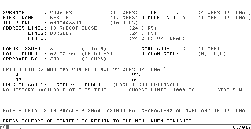
Figure 11-2 shows the map in an account record screen. It’s used for displaying and printing the record, and for additions, modifications, and deletions.
Example 11-1 shows the map definition for this screen; after the code there are notes on some of the macros.
Notes on the Account Detail map
The highlighted numbers(1–6) are not part of the code:
There is a suffix on each of the labels to tell which map the field is from; in this map the suffix is “D”, for detail. This is the same in the menu (M) and is repeated in subsequent maps. Thus, the account number is ACCTM in the menu map and ACCTD in the detail map. This is simply for clarity and to avoid having to use COBOL qualifiers to distinguish between fields with the same name. You could just as easily have used a prefix instead of a suffix; neither is a BMS requirement.
Example 11-1. The Account Detail Screen BMS Macro DefinitionsACCTDTL DFHMDI SIZE=(24,80),CTRL=(FREEKB,PRINT) DFHMDF POS=(01,01),ATTRB=(ASKIP,BRT),LENGTH=8, X INITIAL='ACCOUNTS TITLED DFHMDF POS=(01,19),ATTRB=(ASKIP,NORM),LENGTH=10, X1INITIAL='DETAILS OF'2DFHMDF POS=(01,30),ATTRB=(ASKIP,NORM),LENGTH=14, X INITIAL='ACCOUNT NUMBER' ACCTD DFHMDF POS=(01,45),ATTRB=(ASKIP,BRT),LENGTH=5 DFHMDF POS=(01,51),ATTRB=(ASKIP,NORM),LENGTH=1 DFHMDF POS=(03,01),ATTRB=(ASKIP,BRT),LENGTH=7,INITIAL='SURNAME' DFHMDF POS=(03,14),ATTRB=(ASKIP,BRT),LENGTH=1,INITIAL=':' LNAMED DFHMDF POS=(03,16),ATTRB=(UNPROT,NORM,IC),LENGTH=183DFHMDF POS=(03,35),ATTRB=(ASKIP,NORM),LENGTH=9, X INITIAL='(18 CHRS)' DFHMDF POS=(03,45),ATTRB=(ASKIP,BRT),LENGTH=5,INITIAL='TITLE' DFHMDF POS=(03,56),ATTRB=(ASKIP,BRT),LENGTH=1,INITIAL=':' TTLD DFHMDF POS=(03,58),ATTRB=(UNPROT,NORM),LENGTH=4 DFHMDF POS=(03,63),ATTRB=(ASKIP,NORM),LENGTH=17, X INITIAL='(4 CHRS OPTIONAL)' DFHMDF POS=(04,01),ATTRB=(ASKIP,BRT),LENGTH=10, X INITIAL='FIRST NAME' DFHMDF POS=(04,14),ATTRB=(ASKIP,BRT),LENGTH=1,INITIAL=':' FNAMED DFHMDF POS=(04,16),ATTRB=(UNPROT,NORM),LENGTH=12 DFHMDF POS=(04,29),ATTRB=(ASKIP,NORM),LENGTH=1 DFHMDF POS=(04,35),ATTRB=(ASKIP,NORM),LENGTH=9, X INITIAL='(12 CHRS)' DFHMDF POS=(04,45),ATTRB=(ASKIP,BRT),LENGTH=12, X INITIAL='MIDDLE INIT:' MID DFHMDF POS=(04,58),ATTRB=(UNPROT,NORM),LENGTH=1 DFHMDF POS=(04,60),ATTRB=(ASKIP,NORM),LENGTH=1 DFHMDF POS=(04,63),ATTRB=(ASKIP,NORM),LENGTH=17, X INITIAL='(1 CHR OPTIONAL)' DFHMDF POS=(05,01),ATTRB=(ASKIP,BRT),LENGTH=9, X INITIAL='TELEPHONE' DFHMDF POS=(05,14),ATTRB=(ASKIP,BRT),LENGTH=1,INITIAL=':' TELD DFHMDF POS=(05,16),ATTRB=(NUM,NORM),LENGTH=10 DFHMDF POS=(05,27),ATTRB=(ASKIP,NORM),LENGTH=1 DFHMDF POS=(05,35),ATTRB=(ASKIP,NORM),LENGTH=9, X INITIAL='(10 DIGS)' DFHMDF POS=(06,01),ATTRB=(ASKIP,BRT),LENGTH=14, X INITIAL='ADDRESS LINE1:' ADDR1D DFHMDF POS=(06,16),ATTRB=(UNPROT,NORM),LENGTH=24 DFHMDF POS=(06,41),ATTRB=(ASKIP,NORM),LENGTH=9, X INITIAL='(24 CHRS)' DFHMDF POS=(07,09),ATTRB=(ASKIP,BRT),LENGTH=6,INITIAL='LINE2:' ADDR2D DFHMDF POS=(07,16),ATTRB=(UNPROT,NORM),LENGTH=24 DFHMDF POS=(07,41),ATTRB=(ASKIP,NORM),LENGTH=9, X INITIAL='(24 CHRS)' DFHMDF POS=(08,09),ATTRB=(ASKIP,BRT),LENGTH=6,INITIAL='LINE3:' ADDR3D DFHMDF POS=(08,16),ATTRB=(UNPROT,NORM),LENGTH=24 DFHMDF POS=(08,41),ATTRB=(ASKIP,NORM),LENGTH=18, X INITIAL='(24 CHRS OPTIONAL)' DFHMDF POS=(10,01),ATTRB=(ASKIP,BRT),LENGTH=14, X INITIAL='CARDS ISSUED :' CARDSD DFHMDF POS=(10,16),ATTRB=(NUM,NORM),LENGTH=1 DFHMDF POS=(10,18),ATTRB=(ASKIP,NORM),LENGTH=1 DFHMDF POS=(10,26),ATTRB=(ASKIP,NORM),LENGTH=8, X INITIAL='(1 TO 9)' DFHMDF POS=(10,45),ATTRB=(ASKIP,BRT),LENGTH=12, X INITIAL='CARD CODE :' CCODED DFHMDF POS=(10,58),ATTRB=(UNPROT,NORM),LENGTH=1 DFHMDF POS=(10,60),ATTRB=(ASKIP,NORM),LENGTH=1 DFHMDF POS=(10,63),ATTRB=(ASKIP,NORM),LENGTH=7, X INITIAL='(1 CHR)' DFHMDF POS=(11,01),ATTRB=(ASKIP,BRT),LENGTH=14, X INITIAL='DATE ISSUED :' IMOD DFHMDF POS=(11,16),ATTRB=(NUM,NORM),LENGTH=24IDAYD DFHMDF POS=(11,19),ATTRB=(NUM,NORM),LENGTH=2 IYRD DFHMDF POS=(11,22),ATTRB=(NUM,NORM),LENGTH=2 DFHMDF POS=(11,25),ATTRB=(ASKIP,NORM),LENGTH=11, X INITIAL=' (MM DD YY)' DFHMDF POS=(11,45),ATTRB=(ASKIP,BRT),LENGTH=12, X INITIAL='REASON CODE:' RSND DFHMDF POS=(11,58),ATTRB=(UNPROT,NORM),LENGTH=1 DFHMDF POS=(11,60),ATTRB=(ASKIP,NORM),LENGTH=1 DFHMDF POS=(11,63),ATTRB=(ASKIP,NORM),LENGTH=9, X INITIAL='(N,L,S,R)' DFHMDF POS=(12,01),ATTRB=(ASKIP,BRT),LENGTH=14, X INITIAL='APPROVED BY :' APPRD DFHMDF POS=(12,16),ATTRB=(UNPROT,NORM),LENGTH=3 DFHMDF POS=(12,20),ATTRB=(ASKIP,NORM),LENGTH=1 DFHMDF POS=(12,26),ATTRB=(ASKIP,NORM),LENGTH=8, INITIAL='(3 CHRS)' DFHMDF POS=(14,01),ATTRB=(ASKIP,NORM),LENGTH=52,INITIAL='UPTO OTHERS WHO MAY CHARGE (EACH 32 CHRS OPTIONAL)' DFHMDF POS=(15,05),ATTRB=(ASKIP,BRT),LENGTH=3,INITIAL='O1:' AUTH1D DFHMDF POS=(15,09),ATTRB=(UNPROT,NORM),LENGTH=32 DFHMDF POS=(15,42),ATTRB=(ASKIP,BRT),LENGTH=3,INITIAL='O2:' AUTH2D DFHMDF POS=(15,46),ATTRB=(UNPROT,NORM),LENGTH=32 DFHMDF POS=(15,79),ATTRB=(ASKIP,NORM),LENGTH=1 DFHMDF POS=(16,05),ATTRB=(ASKIP,BRT),LENGTH=3,INITIAL='O3:' AUTH3D DFHMDF POS=(16,09),ATTRB=(UNPROT,NORM),LENGTH=32 DFHMDF POS=(16,42),ATTRB=(ASKIP,BRT),LENGTH=3,INITIAL='O4:' AUTH4D DFHMDF POS=(16,46),ATTRB=(UNPROT,NORM),LENGTH=32 DFHMDF POS=(16,79),ATTRB=(ASKIP,NORM),LENGTH=1 DFHMDF POS=(17,01),ATTRB=(ASKIP,BRT),LENGTH=14, INITIAL='SPECIAL CODE1:' SCODE1D DFHMDF POS=(17,16),ATTRB=(UNPROT,NORM),LENGTH=1 DFHMDF POS=(17,18),ATTRB=(ASKIP,BRT),LENGTH=6,INITIAL='CODE2:' SCODE2D DFHMDF POS=(17,25),ATTRB=(UNPROT,NORM),LENGTH=1 DFHMDF POS=(17,27),ATTRB=(ASKIP,BRT),LENGTH=6,INITIAL='CODE3:' SCODE3D DFHMDF POS=(17,34),ATTRB=(UNPROT,NORM),LENGTH=1 DFHMDF POS=(17,36),ATTRB=(ASKIP,NORM),LENGTH=21, INITIAL='(EACH 1 CHR OPTIONAL)' HISTTLD DFHMDF POS=(18,01),ATTRB=(ASKIP,NORM),LENGTH=33, X5INITIAL='NO HISTORY AVAILABLE AT THIS TIME' DFHMDF POS=(18,35),ATTRB=(ASKIP,NORM),LENGTH=1 LIMTTLD DFHMDF POS=(18,41),ATTRB=(ASKIP,NORM),LENGTH=12, X INITIAL='CHARGE LIMIT' LIMITD DFHMDF POS=(18,54),ATTRB=(ASKIP,NORM),LENGTH=8 DFHMDF POS=(18,63),ATTRB=(ASKIP,NORM),LENGTH=1 STATTLD DFHMDF POS=(18,69),ATTRB=(ASKIP,NORM),LENGTH=6, X INITIAL='STATUS' STATD DFHMDF POS=(18,76),ATTRB=(ASKIP,NORM),LENGTH=2 DFHMDF POS=(18,79),ATTRB=(ASKIP,NORM),LENGTH=1 VFYTLD DFHMDF POS=(20,01),ATTRB=(ASKIP,BRT),LENGTH=26 VFYD DFHMDF POS=(20,28),ATTRB=(ASKIP,NORM),LENGTH=16DFHMDF POS=(20,30),ATTRB=(ASKIP,NORM),LENGTH=1 DFHMDF POS=(22,01),ATTRB=(ASKIP,NORM),LENGTH=78, X INITIAL='NOTE:- DETAILS IN BRACKETS SHOW MAXIMUM NO. CHAX RACTERS ALLOWED AND IF OPTIONAL' MSGD DFHMDF POS=(24,01),ATTRB=(ASKIP,BRT),LENGTH=60 DFHMDF POS=(24,62),ATTRB=(ASKIP,NORM),LENGTH=1In this field, this value applies to the most common situation: display record details. This initial value is not a constant, as it is in the fields without labels, but a default. The field is set to a different value by the program for adds, modifies, and other uses of the screen. Notice that it has a label, so that the program has access to it.
This is normally the first field into which the user is to enter data, and therefore is a good place to put the cursor. This is a default specification; the program can and often overrides it.
You don’t need a stopper field for an input field if another input field follows immediately.
These title fields should appear on all the displays except the skeleton screen for adding new records. It’s easiest to put them in the map, therefore, and simply remove for an add operation. All you have to do is to set the attribute byte to nondisplay in that one case. To enable the program to access the attribute bytes, you need to add labels on the fields.
This field is used only for deletions, so the default value for the attribute byte will be autoskip (ASKIP). That way the user won’t even be aware of the field when using the map for other transactions. For deletions, the program changes the attribute byte to be unprotected.
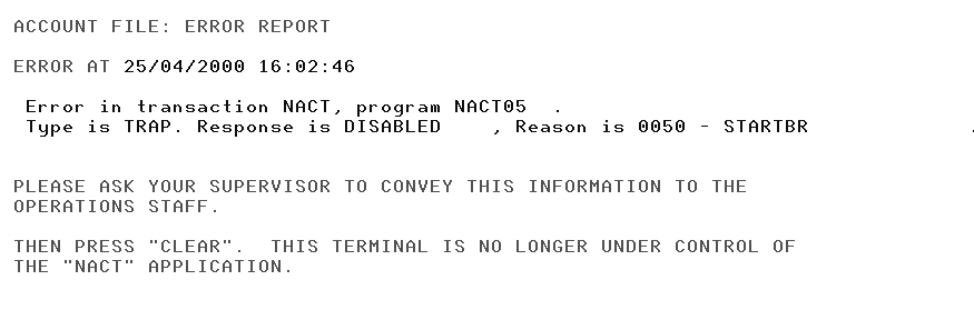
Defining the error map
When CICS abends our transaction, it is stopped in its tracks; detected errors are also processed by the same logic (NACT04). This screen (shown in Figure 11-3) is used to display error information if the transaction abended and was run at a 3270 terminal.
The Mapset
If we put together the three maps that we’ve now defined (the menu map, detail map, and error map), the results are shown in Example 11-2.
ACCTSET DFHMSD TYPE=MAP,MODE=INOUT,LANG=COBOL,
                STORAGE=AUTO,TIOAPFX=YES
 *       MENU MAP.
 ACCTMNU DFHMDI SIZE=(24,80),CTRL=(PRINT,FREEKB)
         DFHMDF ... (all macros for the menu map)
 *
 *       DETAIL MAP.
 ACCTDTL DFHMDI SIZE=(24,80),CTRL=(PRINT,FREEKB)
         DFHMDF ... (all macros for the detail map)
 *
 *    ERROR MAP.
 ACCTERR DFHMDI SIZE=(24,80),CTRL=FREEKB
         DFHMDF ... (all macros for the error map)
         DFHMSD TYPE=FINAL
         END
Symbolic Description Maps
Assembling the macros with TYPE=MAP specified in the DFHMSD macro produces the physical map that CICS uses at execution time. After you’ve done this assembly, you do it all over again, this time specifying TYPE=DSECT. This second assembly produces the symbolic description map, a structure that you copy or include into your program. It’s stored in the copybook or include library specified in the JCL, and its name in that library is the map set name specified in the DFHMSD macro.
This structure is a set of data definitions for all the display fields on the screen, plus information about those fields. It allows your program to refer to these display data fields by name and to manipulate the way in which they are displayed, without worrying about their size or position on the screen.
Copying the Map Structure into a Program
To copy the structures for the maps in a mapset into a program in COBOL, you write a COPY statement like this:
COPY mapset (name).For other languages you use the appropriate include syntax, for example use the import statement in Java or the include statement in C or C++.
Here, mapset (name) is the name of the mapset. This COPY statement usually appears in WORKING-STORAGE, although later you may find reasons to put it in the LINKAGE SECTION. We’ll cover only the WORKING-STORAGE situation. To get the symbolic descriptions for our maps in a program, write:
COPY NACTSET.
Example 11-3 shows you the first few lines of what is copied into your program as a result of this COPY statement. The part shown is generated by the first map in the set, the menu map. It’s followed by similar structures for the other maps. They are very long and very similar in form. They’re all on the accompanying CD-ROM; see “Configuring Your CICS for OS/390 Environment” in Appendix A for details.
01  ACCTMNUI.
     02  FILLER PIC X(12).
     02  SNAMEML    COMP  PIC  S9(4).
     02  SNAMEMF    PICTURE X.
     02  FILLER REDEFINES SNAMEMF.
       03 SNAMEMA    PICTURE X.
     02  SNAMEMI  PIC X(12).
     02  FNAMEML    COMP  PIC  S9(4).
     02  FNAMEMF    PICTURE X.
     02  FILLER REDEFINES FNAMEMF.
       03 FNAMEMA    PICTURE X.
In Example 11-2, you defined the map set to be used for both input and output (by coding MODE=INOUT in the DFHMSD macro); the resulting structure has two parts. The first part corresponds to the input screen, and is always labeled (at the 01 level) with the map name, suffixed by the letter I (for input). The second part corresponds to the output screen, and is labeled with the map name followed by the letter O. The output map always redefines the input map. If you’d specified MODE=IN, only the input part would have been generated, and similarly, MODE=OUT would have produced only the output part. Notice that for each of these map fields, five data subfields are generated.
Notes on DSECTs
Here are some things to keep in mind about DSECTs:
Because of the way the input and output parts of the map structure overlay each other, the -I and the -O subfields for a given map field always redefine each other. That is, SNAMEMI and SNAMEMO occupy the same storage that FNAMEMI and FNAMEMO do, and so on. This turns out to be convenient in coding.
The flag and attribute subfields occupy the same space (REQMF overlays REQMA, ACCTMF overlays ACCTMA, and so on). You don’t have to worry about removing these flags when you’re sending output. Because the four input flag values (X’82’, X’80’, X’02’ and X’00’) don’t represent acceptable output attribute byte values, BMS can distinguish on output between a leftover flag and a new attribute.
When you send a map, you don’t have to put anything in the length field. BMS knows how long the field is from the information in the physical map. The only time you use the length field for an output field is to set the cursor position; this will be explained shortly.
Sending a Map to a Terminal
Now that you’ve defined your maps, you can think about writing them to a terminal. The terminal to which you write, of course, is the one that sent the input and thereby invoked the transaction. This is the only terminal to which a transaction can write directly.
The SEND MAP Command
The EXEC CICS SEND MAP command writes formatted data to a terminal. It looks like this:
EXEC CICS SEND MAP(name) MAPSET(name)
          options
           ...
END-EXEC
The items in this macro are:
- MAP (name)
This specifies the name of the map you want to send. It is limited to 1–7 characters and it’s required. Put it in quotes if it’s a literal.
- MAPSET (name)
This specifies the unsuffixed name (1–7 characters) of the mapset that you want to send. The mapset must reside in the CICS program library. The mapset can be defined either by using RDO or by the autoinstall program when the mapset is first used. If this option is not specified, the name given in the MAP option is assumed to be that of the mapset.
The number of maps per mapset is limited to a maximum of 9998. Put the name in quotes if it’s a literal.
- options
There are a number of options that you can specify; they affect what’s sent and how it is sent. Except where noted, you can use any combination of them. The possibilities are:
- ALARM
This means the same thing in the SEND command as it does in the DFHMSD and DFHMDI macros for the map: it causes the audible alarm to be sounded. The alarm sounds if you specify ALARM in either the map definition or the SEND command.
- CURSOR(data-value)
This can be used in two ways to position the cursor. If you specify a value after CURSOR, it’s the relative position on the screen where the cursor is to be put. Use a single number, such as CURSOR(81) for line 2, column 2 (counting starts at zero and goes across the lines, which on an IBM 3270-system display Model 2 are 80 characters wide). Why column 2? Because the attribute byte goes in column 1, and we want the cursor to appear under the first character of data.
Alternatively, you can specify CURSOR without a value, and use the length subfields in the output map to show which field is to get the cursor; see Positioning the Cursor. In general, we recommend you to position the cursor in this second manner, rather than the first, so that changes in the map layout don’t lead to changes in the program. Both kinds of CURSOR specification override the cursor placement specified in the map.
- DATAONLY
This is the logical opposite of MAPONLY. You use it to modify the variable data in a display that’s already been created. Only the data from your program is sent to the screen. The constants in the map aren’t sent; so you can use this option only after you’ve sent the same map without using the DATAONLY option. We’ll see an example when we send the results of a name search to the terminal in program NACT01.
- ERASE
This causes the entire screen to be erased before what you’re sending is shown.
- ERASEUP (erase all unprotected fields)
This in contrast to ERASE, causes just the unprotected fields on the screen (those with either the UNPROT or NUM attribute) to be erased before your output is placed on the screen. It’s most often used in preparing to read new data from a map that’s already on the screen. Don’t use it at the same time as ERASE; ERASE makes ERASEAUP meaningless.
- FRSET (flag reset)
This turns off the modified data tag in the attribute bytes for all the fields on the screen before what you’re sending is placed there. Once set on, whether by the user or the program, a modified data tag stays on until turned off explicitly, even over several transmissions of the screen. It can be turned off by the program sending a new attribute byte, an FRSET option, or an ERASE, or an ERASEAUP, or by the user pressing the CLEAR key. Like ERASEAUP, the FRSET option is most often used in preparing to read new data from a map already on the screen. It can also reduce the amount of data resent on an error cycle, as we’ll explain in coding our example.
- FREEKB
This means the same thing as it does in the map definition: the keyboard is unlocked if you specify FREEKB in either the map or the SEND command.
- MAPONLY
This specifies that only default data from the map is to be written. In our example application, this option is used when we send the menu map the first time, because there is no information to put into it.
This allows the output of a SEND command to be printed on a printer, just as it does in the map definition. It is in force if specified in either the map or the command.
- FORMFEED
This causes the printer to restore the paper to the top of the next page before the output is printed. This specification has no effect on maps sent to a display, to printers without the features which allow sensing the top of the form, or to printers for which the formfeed feature is not specified in the CICS Terminal Control Table.
Using SEND MAP in the sample application
The first time a map is sent to a terminal occurs in program NACT01, the menu screen is displayed. The command we need is:
EXEC CICS SEND MAP('ACCTMNU') MAPSET(WS-LITS-MAPSET)
          CURSOR(EIBCPOSN) MAPONLY FRSET FREEKB
          RESP(RESPONSE) RESP2(REASON-CODE)
END-EXEC
The option MAPONLY states that only the constants within your map are to be sent, so initializing the screen. NACT01 uses the DATAONLY option when the screen has the constants displayed and only the data fields are to be sent. If either of these options is not set then both the constants and the data are sent. CICS would expect the data to be used for filling in the map to be in a structure whose name is the name (as specified in the MAP option) suffixed with the letter O. So, when we issue the command:
EXEC CICS SEND MAP('ACCTDTL') MAPSET(WS-LITS-MAPSET)
          ERASE FREEKB CURSOR
          RESP(RESPONSE) RESP2(REASON-CODE)
END-EXEC
CICS expects the data for the map to be in a structure within the program (of exactly the sort generated by the map structure generation) named ACCTDTLO. This structure is usually in your WORKING-STORAGE section, but it might be in a LINKAGE area instead.
Tip
There’s an option on the SEND MAP command that lets you specify a data structure other than the one assumed by CICS. We won’t cover it here, but you can find guidance on using it in the CICS Application Programming Guide.
Let’s look at the more common situation in which we’re merging program data into the map. In program NACT01, we’re supposed to build a detail display map for one record and send it to the screen. Since the contents of the screen vary somewhat with the type of request, and we’re using the same screen for all types, this entails the following:
Putting the appropriate title on the map (add, modify, or whatever it happens to be).
Moving the data from the file record to the symbolic map (except for adds).
Adjusting the attribute bytes. The input fields must be protected in a display or delete operation; the verify field must be unprotected for deletes, and the titles at the bottom of the screen must be made nondisplay for adds.
Putting the appropriate user instructions (about what to do next) into the message area.
Putting the cursor in the right place.
Examples Example 11-4 through Example 11-7 show how the necessary code might look for the display of a record.
PERFORM BBAB-MOVE-TO-DETAIL-MAP
MOVE -1 TO SNAMEDL
MOVE 'PRESS "CLEAR" OR "ENTER" TO RETURN TO THE MENU WHEN FINISHED'
 TO  MSGDO
PERFORM BBAC-PROTECT-DETAILS
SET CA-DISPLAYING TO TRUE
The need to move the details read from the file to the map area occurs in several places, so it has been placed in a common routine (BBAB-MOVE-TO-DETAIL-MAP). In order to ensure that the cursor is placed at the beginning of the surname field, its Length field is set to the special value of -1. (More about this later.) An explanatory/operational message is also placed in the map for transmission to the user. Finally the details on display are not modifiable, so we need to protect them by setting their attributes to autoskip (ASKIP). This requirement also occurs in several places so it has been placed in a common routine (BBAC-PROTECT-DETAILS).
 BBAB-MOVE-TO-DETAIL-MAP SECTION.
*
* This routine populates the detail map from the data obtained.
*
 BBAB-010.
     MOVE ACCTDO   IN NACTREC-DATA TO ACCTDO   IN ACCTDTLO
     MOVE SNAMEDO  IN NACTREC-DATA TO SNAMEDO  IN ACCTDTLO
     MOVE FNAMEDO  IN NACTREC-DATA TO FNAMEDO  IN ACCTDTLO
     MOVE MIDO     IN NACTREC-DATA TO MIDO     IN ACCTDTLO
     MOVE TTLDO    IN NACTREC-DATA TO TTLDO    IN ACCTDTLO
     MOVE TELDO    IN NACTREC-DATA TO TELDO    IN ACCTDTLO
     MOVE ADDR1DO  IN NACTREC-DATA TO ADDR1DO  IN ACCTDTLO
     MOVE ADDR2DO  IN NACTREC-DATA TO ADDR2DO  IN ACCTDTLO
     MOVE ADDR3DO  IN NACTREC-DATA TO ADDR3DO  IN ACCTDTLO
     MOVE AUTH1DO  IN NACTREC-DATA TO AUTH1DO  IN ACCTDTLO
     MOVE AUTH2DO  IN NACTREC-DATA TO AUTH2DO  IN ACCTDTLO
     MOVE AUTH3DO  IN NACTREC-DATA TO AUTH3DO  IN ACCTDTLO
     MOVE AUTH4DO  IN NACTREC-DATA TO AUTH4DO  IN ACCTDTLO
     MOVE CARDSDO  IN NACTREC-DATA TO CARDSDO  IN ACCTDTLO
     MOVE IMODO    IN NACTREC-DATA TO IMODO    IN ACCTDTLO
     MOVE IDAYDO   IN NACTREC-DATA TO IDAYDO   IN ACCTDTLO
     MOVE IYRDO    IN NACTREC-DATA TO IYRDO    IN ACCTDTLO
     MOVE RSNDO    IN NACTREC-DATA TO RSNDO    IN ACCTDTLO
     MOVE CCODEDO  IN NACTREC-DATA TO CCODEDO  IN ACCTDTLO
     MOVE APPRDO   IN NACTREC-DATA TO APPRDO   IN ACCTDTLO
     MOVE SCODE1DO IN NACTREC-DATA TO SCODE1DO IN ACCTDTLO
     MOVE SCODE2DO IN NACTREC-DATA TO SCODE2DO IN ACCTDTLO
     MOVE SCODE3DO IN NACTREC-DATA TO SCODE3DO IN ACCTDTLO
     MOVE STATDO   IN NACTREC-DATA TO STATDO   IN ACCTDTLO
     MOVE LIMITDO  IN NACTREC-DATA TO LIMITDO  IN ACCTDTLO
*
 END-BBAB-MOVE-TO-DETAIL-MAP.
     EXIT.
Each field is moved individually to the map area. This looks a bit tedious when coding, but is something which must be done. With a good block editor, this can be done in just a few minutes.
BBAC-PROTECT-DETAILS SECTION.
*
* This routine protects the detail data fields from modification.
*
 BBAC-010.
     MOVE DFHBMASK TO SNAMEDA
                      FNAMEDA
                      MIDA
                      TTLDA
                      TELDA
                      ADDR1DA
                      ADDR2DA
                      ADDR3DA
                      AUTH1DA
                      AUTH2DA
                      AUTH3DA
                      AUTH4DA
                      CARDSDA
                      IMODA
                      IDAYDA
                      IYRDA
                      RSNDA
                      CCODEDA
                      APPRDA
                      SCODE1DA
                      SCODE2DA
                      SCODE3DA
*
 END-BBAC-PROTECT-DETAILS.
     EXIT.
All of the data fields on the screen need to be protected from modification, so the same attribute (DFHBMASK, AUTOSKIP) is set for all of them.
Finally, the SEND MAP command instructs BMS to create and send a data stream to the device by identifying which MAP to use (ACCTDTL) in which MAPSET. Note this latter option references a data name which is included in source code which is copied into the program. The reason for this is to allow flexibility in naming of the objects referenced by the application. The ERASE option is included to ensure residual data on the screen is removed. The FREEKB option ensures that the user is able to continue work without needing to reset the device. The CURSOR option is explained in the following section. The RESP option is used in order to allow the program to deal with an abnormal return in a standard way.
Positioning the Cursor
We said earlier how vital it is to put the cursor where the user wants to start entering data on the screen. One small piece of source code from you can save hundreds of users a couple of seconds each and every time they use your application.
In the first SEND MAP, we relied on the cursor position specified in the map definition. This puts the cursor under the first data position of the surname field, which is where we want it. In subsequent uses, however, we don’t necessarily want the cursor where the map definition puts it. Where we’re using the detail map, we want to use the map default (the LNAMED field) for adds and modifies. For display operations, it doesn’t matter much, there are no fields into which the user may key. For deletes, however, the cursor should be under the verify (VFY) field. In the case of user input errors, we want the cursor under the first field where the user entered incorrect information.
As we said, there are two ways to override the position specified by the IC specification in the map definition:
You can specify a screen position, relative to line 1, column 1 (that is, position 0) in the CURSOR option on the SEND MAP command. (This can be used to ensure that the cursor remains in the same position that the user left it by using the EIBCPOSN field as the argument. This field is described along with the others in the special CICS control area called the EXEC Interface Block (EIB) later.)
You can show that you want the cursor placed under a particular field by setting the associated length subfield to minus one (–1) and specifying CURSOR without a value in your SEND MAP command. This causes BMS to place the cursor under the first data position of the field with this length value. If several fields are flagged by this special length subfield value, the cursor is placed under the first one (as opposed to the last one with ATTRB=IC).
The second procedure is called symbolic cursor positioning, and is a very handy method of positioning the cursor for, say, correcting errors. As the program checks the input, it sets the length subfield to –1 for every field found to be in error. Then, when the map is redisplayed for corrections, BMS automatically puts the cursor under the first field that the user has to correct.
To place the cursor under the verify field on a delete, therefore, all we have to do is:
MOVE -1 TO VFYDL
and specify CURSOR in our SEND MAP command.
Sending Control Information Without Data
In addition to the EXEC CICS SEND MAP command, there is another terminal output command called SEND CONTROL. It allows you to send control information to the terminal without sending any data. That is, you can free/unlock the keyboard, erase all the unprotected fields, and so on, without sending a map.
The SEND CONTROL command looks like this:
EXEC CICS SEND CONTROL
          options
           ...
          RESP(RESPONSE) RESP2(REASON-CODE)
END-EXEC
The options you can use are the same as on a SEND MAP command: ERASE, ERASEUP, FRSET, ALARM, FREEKB, CURSOR, PRINT, and FORMFEED.
There’s an example of this command in program NACT01. The terminal user has just cleared the screen (of the menu map) to indicate that they want to exit from the control of the online account application. The program is supposed to free/unlock the keyboard before returning control to CICS.
Normally, you would do this when writing a message to the terminal. But since we’re not doing that at this point, we must free/unlock the keyboard by an explicit command, instead. Within the sample application the command is:
 BA-SEND-CONTROL SECTION.
*
* End the pseudo-conversational series of tasks.
* Free the user's keyboard and end without saving
* any data.
*
 BA-010.
     EXEC CICS SEND CONTROL
               FREEKB ERASE
               RESP(RESPONSE) RESP2(REASON-CODE)
     END-EXEC
We’ve added the ERASE option to the previous command, so that the user would be ready to start a new transaction. This isn’t strictly necessary if the user has just cleared the screen, but no harm is done to include it.
Receiving Input from a Terminal
There are two ways to receive input from a terminal, either from the RECEIVE MAP command or from input from the keyboard.
The RECEIVE MAP command
When you want to receive input from a terminal, you use the RECEIVE MAP command, which looks like this:
EXEC CICS RECEIVE MAP(MAPNAME) MAPSET(MAPSETNAME)
                  RESP(RESPONSE) RESP2(REASON-CODE)
END-EXEC.
The MAP and MAPSET parameters have exactly the same meaning as for the SEND MAP command. MAP is required and so is MAPSET, unless it is the same as the map name. Again, it does no harm to include it for documentation purposes.
The form of the RECEIVE MAP command below does not specify where the input data is to be placed. This causes CICS to bring the data into a structure whose name is the map name suffixed with the letter I, which is assumed to be in either your WORKING-STORAGE or LINKAGE area.
For example, program NACT01 requires that we receive the filled-in account detail map. The command to do this is:
*
 DA-RECEIVE-DETAIL SECTION.
*
* This routine get the detail input from the user.
*
 DA-010.
     MOVE LOW-VALUES TO ACCTDTLI
*
     EXEC CICS RECEIVE MAP('ACCTDTL') MAPSET(WS-LITS-MAPSET)
                       RESP(RESPONSE) RESP2(REASON-CODE)
     END-EXEC
It brings the input data into a data area named ACCTDTLI, which is expected to have exactly the format produced by the map generation structure ACCTDTL.
As soon as the map is read in, we have access to all the data subfields associated with the map fields. For example, we can test whether the user made any entry in the request field of:
IF REQML = 0
Or we could discover if the user erased the field:
IF REQMF = DFHBMEOF ...
Or we could examine the input in that field:
IF REQMI = 'A'
This last case is discouraged. Generally we need to retain the data the user has input in a separate area that we will keep across the pseudo-conversational series of transactions used to perform the business function. We will therefore need to merge the current user input with whatever had been entered (if relevant) in any previous CICS task relevant to this business operation. Thus any validation or logic determination will be performed from this special area rather than the input directly. One of the main reasons for this relates to the fact that the Input and Output map areas are really descriptions of the same storage as mentioned earlier.
Tip
Although it generally does not affect your program logic, you should be aware that the first time in a transaction that you use the RECEIVE MAP command, it has a slightly different effect from subsequent times. Since it is input from the terminal that causes a transaction to get started in the first place, CICS has always read the first input by the time the transaction starts to execute. Therefore, on this first RECEIVE MAP command, CICS simply arranges the input it already has into the format dictated by your map, and puts the results in a place accessible to your program.
On subsequent RECEIVE MAP commands in the same task, CICS actually waits for and reads input from the terminal. These subsequent RECEIVE MAP s are what make a task conversational. By contrast, a pseudo-conversational task executes at most one RECEIVE MAP command. This is the technique we use in the sample application.
Finding Out What Key the Operator Pressed
There is another technique you may wish to use for processing input from a terminal. The 3270 input stream contains an indication of which attention key caused the input to be transmitted (Enter, Clear, or one of the PA or PF keys).
You can use the EXEC Interface Block Attention Identifier (EIBAID) field to change the flow of control in your program based on which of these attention keys was used.
The EXEC Interface Block (EIB)
Before we explain how to find out what key was used to send the input, we need to introduce one CICS control block. This is the EXEC Interface Block (EIB), and it is the only one that you need to know anything about for the type of applications described in this book.
You can write programs without using even this one, but it contains information that is very useful and is sometimes really essential.
There is one EIB for each task, and it exists for the duration of the task. Every program that executes as part of the task has access to the same EIB. You can address the fields in it directly in your COBOL program without any preliminaries. You should only read these fields, however, not try to modify them. All of the EIB fields are discussed in detail in the CICS Application Programming Reference, but the ones that are of general use follow.
- EIBAID
Contains the attention identifier (AID) associated with the last terminal control (for example, which keyboard key was last pressed) or basic mapping support (BMS) input operation from a display device such as the 3270. It is coded as shown in later AID byte definitions.
- EIBCALEN
Contains the length of the communication area that has been passed to the application program from the last program, using the COMMAREA and LENGTH options. If no communication area is passed, this field contains zeros.
- EIBCPOSN
Contains the position of the cursor (the cursor address) at the time of the last input command for 3270-like devices only. This position is expressed as a single number relative to position zero on the screen (row 1, column 1), in the same way that you specify the CURSOR parameter on a SEND MAP command. This field was mentioned earlier (in the section Positioning the Cursor) when indicating that there is a technique for retaining the current position of the cursor on the screen.
- EIBDATE
Contains the date the task is started; this field is updated by the ASKTIME command. The date is in packed decimal form (0CYYDDD+) where C shows the century with values 0 for the 1900s and 1 for the 2000s. For example, the dates 31 December 1999 and 1 January 2000 have EIBDATE values of 0099365 and 0100001, respectively.
- EIBDS
Contains the symbolic identifier of the last data set (file) referred to in a file control request (command), for example, read a record, write a record.
- EIBFN
Contains a code that identifies the last CICS command issued by the task in “PIC X(2)” format. The first byte of this two-byte field indicates the type of command. File commands have a code of X’06’, BMS commands are X’18’, and so on. The second byte tells which particular command: X’0602’ means READ, X’0604’ means WRITE, and so on. A list of the codes for the API appears in the CICS Application Programming Reference; a list of the codes for the SPI appears in the CICS System Programming Reference. These books are included on the CD-ROM that comes with this book.
- EIBRESP
Contains a number corresponding to the RESP condition that has been raised. There is a complete list of symbolic names for these numbers in the CICS Application Programming Reference.
- EIBRESP2
Contains more detailed information that may help explain why the RESP condition has been raised. This field contains meaningful values for specific commands.
Tip
The values in the EIBRESP and EIBRESP2 fields of the EIB can also be interrogated using the RESP and RESP2 values on an EXEC CICS command; see Example 11-9.
- EIBRSRCE
Contains the symbolic identifier (name) of the resource being accessed by the latest executed command. For file commands, this value is the FILE parameter, so that EIBRSRCE has the same value as EIBDS after such a command. For BMS commands it is the name of the terminal (the four-character name of the input terminal, or EIBTRMID in the context of this book).
- EIBTASKN
Contains the task number assigned to the task by CICS. This number appears in trace table entries generated while the task is in control. CICS assigns a sequential number to each task it executes, and this number is used to identify entries for the task in the Trace Table (if you want to know more about trace and dump refer to the CICS Problem Determination Guide).
- EIBTIME
Contains the time at which the current task started, also in “PIC S9(7) COMP-3” form, with one leading zero: “0HHMMSS+”. Note that for simpler date processing, we recommend the use of the ASKTIME and FORMATTIME commands.
- EIBTRMID
Contains the name of the terminal (terminal or logical unit) associated with the task.
- EIBTRNID
Contains the symbolic transaction identifier of the task.
AID byte definitions
Getting back to the attention identifier, we can also tell what key was used to send the input by looking at the EIBAID field, as noted above.
When a transaction is started,EIBAID is set according to the key used to send the input that caused the transaction to get started. It retains this value through the first RECEIVE command, which only formats the input already read, until after a subsequent RECEIVE, at which time it is set to the value used to send that input from the terminal.
EIBAID is one byte long and holds the actual attention identifier value used in the 3270 input stream. As it is hard to remember these values and hard to understand code containing them, it is a good idea to use symbolic rather than absolute values when testing EIBAID. CICS provides you with a precoded set which you simply copy into your COBOL program by writing:
COPY DFHAID.
in your WORKING-STORAGE SECTION. For other languages the data structure gets placed in a library along with similar copy or include statements to add it into your program in the normal way. Example 11-8 shows some of the definitions this brings into your program.
01  DFHAID.
     02  DFHNULL       PIC X VALUE IS ' '.
     02  DFHENTER      PIC X VALUE IS ''''.
     02  DFHCLEAR      PIC X VALUE IS '_'.
     02  DFHCLRP       PIC X VALUE IS ' '.
     02  DFHPEN        PIC X VALUE IS '='.
     02  DFHOPID       PIC X VALUE IS 'W'.
     02  DFHMSRE       PIC X VALUE IS 'X'.
     02  DFHSTRF       PIC X VALUE IS ' '.
     02  DFHTRIG       PIC X VALUE IS '"'.
     02  DFHPA1        PIC X VALUE IS '%'.
     02  DFHPA2        PIC X VALUE IS '>'.
     02  DFHPA3        PIC X VALUE IS ','.
     02  DFHPF1        PIC X VALUE IS '1'.
     02  DFHPF2        PIC X VALUE IS '2'.
         . . .
         . . .
     02  DFHPF23       PIC X VALUE IS '.'.
     02  DFHPF24       PIC X VALUE IS '<'.
DFHENTER is the Enter key, DFHPA1 is Program Attention (PA) Key 1, DFHPF1 is Program Function (PF) Key 1, and so on. As in the case of the DFHBMSCA macro, any values above that appear to be spaces are not; they correspond to bit patterns for which there is no printable character.
Errors on BMS Commands
As we cover each group of commands in this book, we’ll discuss what can go wrong. We’ll classify errors according to the categories and suggest how you might want to handle them in your coding.
There is really only one type of error that we can expect to occur in the subset of BMS commands and map options that we’ve covered here. This is known as MAPFAIL. There are other types of failure and they are listed in the CICS Application Programming Reference.
MAPFAIL errors
MAPFAIL occurs on a RECEIVE MAP command when there are no fields at all on the screen for BMS to map for you. This happens if you issue a RECEIVE MAP after the user has pressed a Clear or a Program Attention key. These are known as “short-read” keys because the only data that flows from the termial is the keycode, no data from the terminal is passed. It can also occur even if the user does not use a short-read key. If, for example, you send a screen to be filled in (without any fields in which the map or the program turns on the modified-data tag), and the user presses the Enter key or one of the program function keys without keying any data into the screen, you’ll get MAPFAIL.
The reason for the failure is essentially the same in both cases. With the short read, the terminal does not send any screen data; hence no fields. In the other case, there are no fields to send; no modified-data tags have been turned on.
MAPFAIL is almost invariably a user error (and, hence, an expected program condition). It may occur on almost any RECEIVE MAP, and therefore you should handle it explicitly in the program. For instance, Example 11-9 shows the code that the example application contains to deal with a MAPFAIL that occurs when the menu map is received.
 BB-MENU-DATA-ENTERED SECTION.
*
* Obtain the input (if any) from the user.
*
 BB-010.
     MOVE LOW-VALUES TO ACCTMNUI
*
     EXEC CICS RECEIVE MAP('ACCTMNU') MAPSET(WS-LITS-MAPSET)
               RESP(RESPONSE) RESP2(REASON-CODE)
     END-EXEC
*
     IF  (RESPONSE NOT = DFHRESP(NORMAL))
     AND (RESPONSE NOT = DFHRESP(MAPFAIL))
          PERFORM Y-UNEXPECTED-ERROR
     END-IF
This code is designed to make the occurrence of MAPFAIL somewhat transparent to the program. It is important to realize the difference in what BMS does when there is and there is not data to map. If BMS finds data to map, it clears the target map area to nulls (LOW-VALUES) before setting up the appropriate Length, Flag and Input fields. If BMS finds no data to map, it immediately raises the MAPFAIL condition and leaves the target map area exactly as it was.
In order to ensure the basic logic of the program can proceed regardless of the input, it primes the target map area with LOW-VALUES (nulls) before requesting BMS services. We then detect that the response from BMS is acceptable by the test of the EIBRESP value. Note that the key causing the initiation of the transaction was tested before we reached this part of the program, so we know it isn’t the CLEAR key.
Starting Another Task, and Other Time Services
CICS allows one transaction (task) to start another one, as we noted in our discussion about printed output. The usual reason for doing this is the one that arose in our example: the originating task needs access to some facility it does not own, usually a terminal other than the input terminal. In our case, we needed a printer to print the log of account file changes. There are sometimes other reasons as well. You might want a task to be executed at a particular time, or you might want it to run at a different priority from the original task, for instance.
Starting Another Task
The command to start another task is:
EXEC CICS START TRANSID(name) TERMID(termid)
                FROM(data-area)  LENGTH(data-value)
                options
END-EXEC
The options for this command are:
- TRANSID(name)
Specifies the identifier (1–4 characters) of the transaction that is to be started. This parameter is required. If the identifier is a literal, enclose it in quotes.
- TERMID(name)
Specifies the symbolic identifier (1–4 alphanumeric characters) of the principal facility associated with a transaction to be started as a result of a START command. When this parameter is omitted the started task runs without a principal facility.
- FROM(data-area)
Specifies the name of the data area that contains data to be passed to the transaction being started. This parameter is optional.
- LENGTH(data-value)
Specifies the length of the data to be passed for the new task.
- options (can be either INTERVAL or TIME)
- INTERVAL(hhmmss)
Specifies the expiration time as an interval of time that is to elapse from the time at which the START command is issued. The mm and ss are each in the range 0–59. The time specified is added to the current clock time by CICS when the command is executed to calculate the expiration time.
- TIME(hhmmss)
Specifies the time when a new task should be started. When using the C language, you are recommended to use the AFTER/AT HOURS, MINUTES, and SECONDS options, as C does not provide a packed decimal data type. You may use TIME, but if the value specified is not an integer constant, the application is responsible for ensuring that the value passed to CICS is in packed decimal format.
If you don’t specify either INTERVAL or TIME, CICS assumes that you would like INTERVAL(0), which means right away.
Retrieving data passed to the START command
If data is passed in the START command, the transaction that gets started uses the EXEC CICS RETRIEVE command to get access to this data. The syntax of the RETRIEVE command looks like this:
EXEC CICS RETRIEVE
          INTO(data-area)LENGTH(length)
END-EXEC
Notice the difference between this RETRIEVE command and the RECEIVE command described in The RECEIVE MAP command. Both commands may be used to get the initial input to a transaction, but they aren’t interchangeable: RECEIVE must be used in transactions that are initiated by input from a terminal, and RETRIEVE must be used in transactions that were started by another transaction. The options for this command are:
- INTO(data-area)
Specifies the user data area into which retrieved data is to be written.
- LENGTH(data-value)
Specifies the length of the data area the retrieved data is written into.
Using the START and RETRIEVE commands in the sample application
In our sample application, program NACT01 uses the START command when a user asks for a record to be printed:
EXEC CICS START TRANSID(PRINT-TRANSID) TERMID(CA-PRINTER)
                FROM(ACCTDTLO)
                RESP(RESPONSE) RESP2(REASON-CODE)
ENDEXEC
This START command tells CICS to start transaction PRINT-TRANSID as soon as possible after the printer whose name is in data area CA-PRINTER is available to be its terminal.
Program NACT03, running on behalf of this transaction, in turn issues the following RETRIEVE command to retrieve the data passed from program NACT01:
EXEC CICS RETRIEVE
          INTO(ACCTDTLI)
          RESP(RESPONSE) RESP2(REASON-CODE)
END-EXEC
ACCTDTLO and ACCTDTLI refer to the symbolic map structure, located in WORKING-STORAGE in both programs. The map, of course, contains the data read by transaction NACT. This data is to be printed by transaction NACP.
Errors on the START and RETRIEVE commands
A number of different problems may arise in connection with the START and RETRIEVE commands that we’ve described. Possible errors are:
- INVTSREQ
Means that the CICS system support for temporary storage, which is required for START commands that specify the FROM option, was not present when a RETRIEVE command was issued. This error is an example of the system/application mismatch (category 4) described in Handling Errors in Chapter 4.
- IOERR
Means an input/output error on the temporary storage data set where the data to be passed is stored on a RETRIEVE or START command.
- LENGERR
Occurs when the length of the data retrieved by a RETRIEVE command exceeds the value specified in the LENGTH parameter for the command. LENGERR usually means an error in the program logic.
- NOTFND
Means that the requested data could not be found in temporary storage on a RETRIEVE command. If a task issuing a RETRIEVE command was not started by a START command, or if it was started by a START command with no FROM parameter (in other words, no data), this condition will occur. Again, it usually means a programming error.
- TERMIDERR
Occurs when the terminal specified in the TERMID parameter in a START command cannot be found in the Terminal Control Table. During the test phase it usually indicates a problem in the program logic; on a production system, it usually means that something has happened to the terminal.
- TRANSIDERR
Means that the transaction identifier specified in a START command cannot be found in the list of installed transaction definitions. Like TERMIDERR, it usually means a programming error during the development of an application, or table damage if it occurs on a production system.
Local Printing (NACT03): Requests for Printing
This program is invoked asynchronously in order to print on a CICS-attached printer. It prints the data passed to it in the same form as it appears on a display screen as generated by NACT01.
Essentially this program implements the local print processing. There are some important points to note about the implementation of this logic:
The input data is expected to be in a form already suitable for printing.
The Return to caller implies ending the CICS task.
The program implements the standard error handling approach designed for the application. It uses CICS facilities to identify program NACT04 as the one to be invoked in the event of an abend occurring as well as using it to process any unexpected errors that may arise.
NACT03 does several jobs, all related to printed output (as opposed to display output). When it is invoked by transaction NACP, it completes the request for printed output of a record in the account file.
Warning
NACP should not be confused with network abend control program DFHNACP. In this book it is used to refer to the print transaction.
Transaction NACT processed the initial stages of the print request, checking the input, reading the record to be printed, and building the detailed screen from the information in the file record. It then requested that transaction NACP be started with the required printer as its terminal. The processing in NACP is outlined here:
Retrieve the screen image prepared and saved for this purpose in program NACT01:
EXEC CICS RETRIEVE
          INTO(ACCTDTLO)
          RESP(RESPONSE) RESP2(REASON-CODE)
END-EXEC
Send this screen to the terminal, in this case the printer, named by the user in the print request.
EXEC CICS SEND MAP('ACCTDTL') MAPSET(WS-LITS-MAPSET)
               PRINT ERASE
               RESP(RESPONSE) RESP2(REASON-CODE)
END-EXEC
Transfer control to the error handling program in one of the following two ways:
EXEC CICS XCTL PROGRAM(ABEND-PROGRAM)
          COMMAREA(WS-ERRH-ERROR-COMMAREA)
          RESP(RESPONSE) RESP2(REASON-CODE)
END-EXEC
or:
EXEC CICS ABEND ABCODE(WS-LITS-ABEND-ERROR-ABEND)
END-EXEC
Return control to CICS. Don’t set any next transid because there’s no need to do so for terminals that never send unsolicited input. Also, we don’t know what transaction should be executed next at this printer.
EXEC CICS RETURN
END-EXEC
What’s Next…
That’s all about the 3270 interface. Chapter 12, describes how to create a similar interface, but this time designing the screen using Visual Basic and then linking that to the business logic by a CICS client.