Chapter 12. Designing the Visual Basic Component
In this chapter:
In Part I of the book, we looked at the various departments in the KanDoIT company, and their requirements for the new business application. Now let’s look in a little more detail at the customer services department.
The customer services department is, as its name implies, driven by KanDoIT’s customers. Typically, much of its work is following up customer account enquiries, most of which are received over the telephone. Sometimes customers will know their account number; often they won’t. Finding the correct information quickly is always going to be a critical need.
The purpose of the Visual Basic component is to provide the customer services department with an easy-to-use graphical user interface (GUI), for their work with customer account records. Of course it’s important that representatives of the customer services department work closely with the Visual Basic programmers to ensure that the design of the GUI really meets the department’s requirements.
Understanding What the Component Needs to Do
In Chapter 4, we decided which services that the COBOL business logic component would provide within the sample application.
It would:
Return the contents of a customer account record, given an account number.
Add a new customer account record, given an account number and customer data.
Modify an existing account record, given an account number and modified data.
Delete an account record, given an account number.
Access customer account records by name; that is, given a name or part of a name, return a list of matching names with corresponding account numbers and addresses.
The Visual Basic GUI supplies the interfaces to the services provided by the COBOL component. The first four services are supplied by the program NACT02 (the business logic); the last is supplied by NACT05 (the browse component).
Security is handled by means of a Log In panel when the Visual Basic component is started. The user must supply a valid user ID and password where this is required by the CICS server.
Most Visual Basic applications would typically include:
A print option to print a displayed form.
Online help facilities to guide the user through the application. These should include details of how to contact the helpdesk.
Data validation, for checking data in the application.
We will build these options into our application.
Designing the Graphical User Interface
To the user (in this case, staff in the customer services department), the user interface is the application; first impressions are critical in determining whether or not the application will be a success. Therefore it is vital that its design is carefully thought out. The user interface designer needs to consider such things as whether to use a single document interface (SDI) or multiple document interface (MDI), how many forms will be required, the level of help needed by the user, and so on. The Programmer’s Guide provided with Visual Basic documents the different options available in detail.
There may also be company standards that you have to follow. For example there may be rules relating to the naming of windows, so that your helpdesk is able to identify a user’s problem more easily.
The design used for the GUI in this application is simply an example of what can be done. It is not meant to be a definitive guide, and it could no doubt benefit from further modifications. Design should be an ongoing, iterative process based on the needs, observations, and new demands of users.
Three forms are required for the KanDoIT application: a Log In panel, a Main Menu, and an Accounts Details form. Since only one form needs to be displayed at a time, the Visual Basic GUI makes use of an SDI design.
Where there are a limited set of options that the user can choose from it is useful to use either a list box (also known as a Selection menu) or combo box (also known as textarea menu) to make these available to the user. A list box provides the user with a series of options from which to select. A combo box allows the user to either type in a value or select from a list.
So having decided that you need three panels, what do you need to include in each panel and what design considerations should you take into account?
Designing the Log In panel
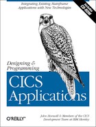
The Log In panel (see Figure 12-1) appears when the application is first started. The User Name and Password required are those defined to the CICS Server for security purposes for the particular user. In our case simple Visual Basic routines have been used to convert the input to uppercase.
Information typed in the Log In panel is passed to CICS, where the user is authenticated.
Designing the Main Menu
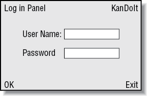
Once the user has logged in, Figure 12-2 appears on the screen. It comprises two main parts:
- Search by Name
Makes use of the Browse application, NACT05. On a screen, most users read from left to right and top to bottom, so the input fields for User Name (rurname) and Password have been placed in the top left-hand corner as this is the point at which their eyes will look first.
- Account Request
Makes use of the CRUD application (NACT02) and requires the Account Number.
To ensure that only valid requests are made a list box is used to show the available request types. The user needs only to click on the required entry shown in the list. A list box is also used to show the hits made for a search. The account number of the selected customer is automatically placed in the Account Number field. A vertical scroll bar allows the user to find the required entry where the length of the list exceeds the display space.
In addition to list boxes, other GUI components used in the Main Menu include:
- Tab Indexes
These are used for the various data input fields and ensure that the cursor is positioned correctly. Initially the cursor is placed in the first field we would normally expect the user to complete. Pressing the Tab key then takes the user through the various data input fields on the menu page in the order we would expect them to be completed.
- Shortcuts or Fast Paths
These have been set up for the command buttons and menu bar choices. A shortcut is set up by prefacing one of the letters in the caption with the ampersand symbol (&). For example, &Submit Search appears on the corresponding command button as Submit Search, and can be activated by the shortcut <Alt> S.
Experienced users may choose to use the tabs and shortcuts provided rather than using the mouse pointer (assuming a mouse is available), to select fields and click on the command buttons.
In many cases a user would search for a particular customer name, and then do an account request based on an entry from the list displayed. Selecting an entry from the resulting list box causes the selected account number to be entered in the Account Number box for the Account Request part of the form.
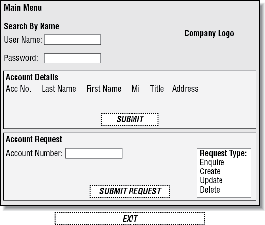
The Account Details form is based on the input form on which details are supplied to the operator. Because the details required for the various request options are generally the same, it makes sense to use the same basic form with minor alterations to tailor it for the individual options.
Two command buttons for particular request types have been added to the Account Details form: Confirm Delete and Create Account. Depending on the request made, these are displayed or hidden as appropriate. The window shown in Figure 12-3 is an enquiry screen, so the command button doesn’t appear. Similarly, when creating a new account the user has no requirement for the history section at the bottom of the form, so this is hidden.
As with the Main Menu, the Tab Index property of the various input objects has been set to provide the user with a logical progression through the data entry fields on the form.
A combo box has been used for the Reason Code to allow users to either type in the appropriate letter directly, or display a list of the available codes from which they can select. The Reason Code is a one-character code used to identify the reason for a charge card being issued. Valid codes are:
N for New
L for Lost
S for Stolen
R for Replacement
An experienced user may well prefer to type in the value directly rather than displaying the list and then selecting a value.
Designing the Print Function
The simplest way of printing a form on a local printer is to use the PrintForm method. This prints all visible objects and bitmaps from the form that the user has opened.
The printer to use is determined by the Control Panel settings for a Windows NT workstation.
When you are coding this there are various options you can choose, including:
Designing the Online Help
The purpose of the online help is to provide information at the point when the user needs it. There are various types of help information that are available using Visual Basic:
- Tooltip text
Information is displayed to the user when the mouse pointer passes over a given GUI object such as an input field or command button. This provides a simple contextual help aid.
- WhatsThisHelp facility
This can be invoked by the user in different ways, but like tooltip text, it is always context-sensitive. One of the most common techniques is to set up a WhatsThisHelp button on the title bar. The user then clicks the button, drags the WhatsThisHelp icon to a control, then clicks again to see the associated help. WhatsThisHelp can be used where a more detailed explanation than that which would normally be given in a tool tip is required.
- Help options
The menu bar for Visual Basic applications normally includes a Help option. The sub-menu from this normally includes an About item giving details of the release of the Visual Basic application and any copyright information. This model has been implemented in our application.
Additional help items give the user more details about each of the main options called from the Main Menu, namely Search by Name and Account Request. As the Account Request item is more complex than the Search by Name item the help has been further broken down to include not only a brief description of the application but further details on each of the request types that can be used as separate items.
A similar setup is used on the Account Details form. Help relative to the chosen action, such as create account or delete account, will appear in the option list depending on the choice made on the menu form. Only those topics relevant to the chosen action are made available when the menu is displayed.
- Helpdesk
Instructions need to be provided telling the user how to contact the helpdesk.
Designing the Data Validation
To reduce the overhead in CICS client to server calls, it is best to validate the data being sent within the Visual Basic application itself. This means that our component should never receive server-based application error messages. So we need to add data validation routines to the Visual Basic application.
It is important to have a clear understanding of what checks are performed in the existing BMS map-based application and, where appropriate, mirror these in the new Visual Basic application. Here are some of the things we need to consider:
Which fields need to contain just numeric values?
Are supplied numeric values within the value range for that field?
Which fields must contain only alphabetic characters?
Is the length of supplied field valid?
Do date fields contain a properly formatted date value (for example, dd/mm/yyyy format) acceptable to the CICS application? Also, is the date valid (for example, not 31 February 2000)?
Which fields can be assumed to contain default values when left empty?
Have all required fields been completed?
Which fields need to be converted to uppercase for key matching in the CICS application?
Designing Access to and Control of the CICS Application
To communicate with our CICS business logic application on the OS/390 server, the Visual Basic component uses the CICS External Call Interface (ECI) API. This is explained later in Understanding the CICS External Call Interface (ECI). The ECI enables a non-CICS client application to call a CICS program synchronously or asynchronously, as a subroutine. The client program communicates with the server CICS program, using a data area called a COMMAREA. Check back with Saving Data: Using a Scratchpad Facility in Chapter 5 if you have forgotten what a COMMAREA means in CICS.
In making use of the CICS ECI, we have chosen to implement two different access methods, so that you can compare and contrast the approaches:
The first of these uses the native CICS API. This requires the Visual Basic application programmer to have a reasonable understanding of what CICS requires in terms of the COMMAREA field definitions used by the CICS applications, as well as the ability to set up various buffers that are needed in the sending and receiving of the data. The bulk of the code for this method is contained in the Visual Basic module comsubs.bas.
The second method makes use of the VisualAge Interspace product. This product enables the Visual Basic application programmer to make use of CICS applications easily, without the need to understand exactly what CICS is doing. Within Interspace, the programmer can create the module that is required to communicate with a given CICS application, and then include it in any Visual Basic application that needs to use that CICS application.
Both of these methods are discussed in greater detail later in this chapter. Whichever of these two methods is used, the underlying form of communication is the same; this is illustrated in Figure 12-4.
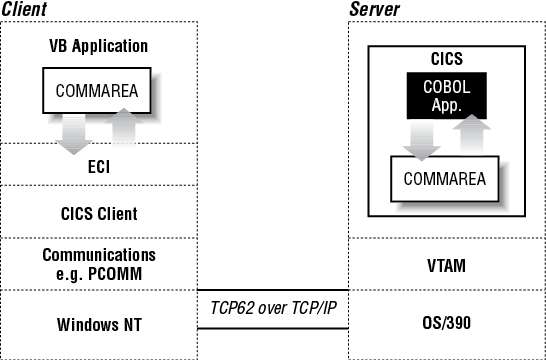
The COMMAREA is passed to the CICS server on the call, and the CICS program typically populates it with data accessed from files or databases. The data is then returned to the client for manipulation or display.
In line with good coding practice, the two programs in the business logic component (NACT02 and NACT05) that are used for our example only make use of field definitions of data type CHAR for the COMMAREA. This greatly simplifies the conversion of data flowing between the Windows NT workstation and the OS/390 server.
The use of the CICS ECI requires us to think about the number of communication flows that need to be transmitted between the CICS client and the CICS server.
Taking the NACT02 application as an example, we are provided with a choice of the following commands. In each case, the actual value entered in the COMMAREA is the initial letter:
| Enquiry (Read without Lock) |
| Create |
| Delete |
| Update |
| Read with Lock |
| Lock |
| Free |
For a simple Enquiry, only one communication with the server is required.
For an Update of an existing record, the following commands need to be issued using the CICS ECI to the NACT02 application:
- Read with Lock
Displays the existing record data for subsequent modification and prevents other users from updating the record. The response code for Read with Lock needs to be checked to verify that the record is not locked by another user.
- Update
Sends the modified record details when completed and releases the record.
For new record creation, the following commands are required:
- Enquiry
Checks whether a record already exists. A non-zero response code indicates that no record exists for the specified account number or that the database is off-line.
- Lock
Locks the account number that is intended for use in the new record.
- Create
Creates the new record with details entered by the user.
The options available to the user have been limited to the following:
| Enquiry |
| Create |
| Delete |
| Update |
This ensures that unnecessary locks are not performed. Based on the type of command entered, the Visual Basic application determines when to issue a Read with Lock in line with the logic used for this purpose in NACT02. NACT02 uses the checks carried out by NACT01 (which handles the presentation logic for BMS screens) if any additional functions should be issued for the selected option.
Understanding the CICS External Call Interface (ECI)
The CICS External Call Interface (ECI) is an integral component in the communication between the Visual Basic component and the business application logic. Before going on to look at the two access methods, using the native CICS API and VisualAge Interspace, you may find it helpful to understand more about the ECI. Figure 12-4 shows a high-level overview of the process. The ECI enables a non-CICS application to call a CICS program in a CICS server. Any program that can be called as a subroutine using EXEC CICS LINK, and which does not require a CICS terminal, may be accessed by this means. Data is exchanged between the two applications by means of a COMMAREA. The non-CICS application does not issue any CICS calls itself; the CICS commands are only issued by the called program running in the server.
The non-CICS application builds two data areas, then issues the ECI call. The CICS client then sends the request to the CICS server.
The server receives the request, performs any required data translation, and starts a transaction for the ECI request. Any translation of data required is performed in the server. Once the transaction is complete, the CICS server returns the updated COMMAREA to the CICS client. Provided the return code supplied indicates that the call was successful, the updated COMMAREA can then be used.
In the simplest case in our example, the ECI is used to call a single CICS program with simple synchronous calls. Additional options include the use of asynchronous calls and multiple calls within a single unit of work, however, these options are outside the scope of this book.
The ECI is the recommended interface for the development of new client/server applications. Its call structure easily divides the presentation logic (usually in the client) from the business logic in the CICS application (usually in the server), offering application designers maximum flexibility.
Using the ECI
The first of the data areas used by the non-CICS application is used to hold the COMMAREA. The COMMAREA contains all of the data to be passed to the CICS application that is to be called. On completion, the CICS application will return the updated COMMAREA. The maximum size of COMMAREA that can be used is 32,500 bytes; data areas larger than this must be segmented.
The second data area used by the non-CICS application is the ECI parameter block. Parameters passed in this block include items such as:
The type of ECI call to be made
The name of the CICS program to be called
The user ID and password to be used
The address and length of the COMMAREA
The return code
It is important that the ECI parameter block is initialized with nulls (binary zeros).
Normally the return code from the CICS application will be contained within the COMMAREA. Additional information will be passed back within the ECI parameter block for system errors and CICS abend codes when the transaction that started the CICS program has ended abnormally.
Initiating the CICS client
For Windows NT, Start Client and Stop Client options are provided under the CICS Client for Windows NT entry in the Programs List. The CICS client also starts automatically when an application issues the first client call.
Data Conversion Between the CICS Universal Client and CICS Transaction Server
CICS Transaction Server for OS/390 uses an EBCDIC codepage for character data, whereas the CICS Universal Client for Windows NT uses an ASCII codepage. Therefore, the COMMAREAs within an ECI request require data conversion.
The rule for data conversion within CICS is that the conversion occurs on the system that owns the resource. Our sample CICS applications reside on CICS Transaction Server for OS/390, therefore it is CICS Transaction Server for OS/390 that performs the data conversion.
For inbound ECI requests, CICS Transaction Server for OS/390 uses the DFHCNV data conversion macro to convert the COMMAREA from ASCII to EBCDIC.
Where individual fields within the COMMAREA are not to be interpreted as having a character data type they will need to have entries giving their offset and length, and details of the data type to be used. By making sure the COMMAREA used by the ECI is entirely character-based, the need for involved entries within the DFHCNV macro is removed and the processing overhead significantly reduced.
Accessing Applications on the CICS Server with Standard CICS Object-Oriented Support
The CICS Clients technology provides programming support for procedural or object-oriented programming. This is helpful to the Visual Basic programmer, in that it hides much of the complexity of communication to CICS inside a simple external shell. Extended support is based on the provision of an ECI class library modeling the full function of the ECI in an object-oriented way.
Using the CICS Client Component Object Module (COM) libraries
The COM libraries introduced with IBM CICS Universal Client Version 3.1 greatly simplify linking from Visual Basic applications providing COM classes for the CICS ECI and EPI on Microsoft Windows NT, Windows 95, or Windows 98.
These COM classes can be accessed from Microsoft Visual Basic, from Visual Basic for Applications (which is provided built-in to applications such as Microsoft Excel Version 5.0), and from VBScript.
The sample Visual Basic application makes use of the ECI COM library. Two interfaces are provided for each COM class. The newer of these is the Custom Interface provided for use with Visual Basic, which is much faster than the IDispatch provided to support older Visual Basic applications and VBScript. The sample makes use of the Custom Interface.
The interfaces, their methods, and their parameters can be viewed using the Microsoft Object Viewer, or the Object Browser provided within Visual Basic Version 5.
The COM objects supplied for use with the CICS ECI in the CclECILib library are listed in Table 12-1.
In addition, the COM classes in Table 12-2 are also supplied for use with the objects listed in Table 12-1.
In addition, the COM classes in Table 12-2 are also supplied for use with the objects listed in Table 12-1.
COM Class | Description |
CclConnectStatusCodes | Set of codes to indicate server connection availability. |
CclECIExceptionCodes | Set of exception codes for connection failure. |
CclFlowCallTypes | Set of call types associated with CclFlow. |
CclFlowSyncTypes | Set of CICS interaction types, either synchronous or deferred synchronous. These are the only two types of calls supported with Visual Basic. |
Accessing Applications on the CICS Server Using the VisualAge Interspace API
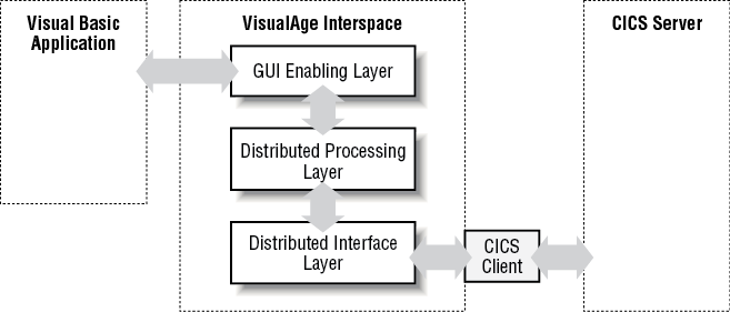
The VisualAge Interspace product minimizes, as far as possible, what the user has to code in order to communicate with a CICS Server application. It provides a simple API that can be used from within a number of different front ends, such as Visual Basic, PowerBuilder, and VisualAge for Java, to link through to CICS and various other middleware services. This API is divided into three layers to provide maximum functionality and flexibility in any distributed environment:
- GUI-Enabling Layer (GEL)
The top layer; provides the Visual Basic developer with a way of invoking middleware services.
- Distributed Processing Layer (DPL)
The middle layer; provides a common API that is not dependent on the underlying middleware.
- Distributed Interface Layer (DIL)
The bottom layer; translates DPL-layer functions into the appropriate middleware API functions.
Each layer is constructed using the layer below it to ensure a consistent programming interface regardless of the underlying implementation. Figure 12-5 illustrates these principles. The online help file provided with VisualAge Interspace is a reference guide to the functions in the top layer.
Warning
The Visual Basic programmer needs to include the VisualAge Interspace modules dcidpl.bas and dcigel.bas in any Visual Basic Project that needs to link to a CICS server application.
Communications with CICS applications are handled by means of services. VisualAge Interspace also includes a tool, the Service Interface Painter, which simplifies the process of developing and testing these services for specific CICS server applications. The Service Interface Painter is used to define an application’s services, generate code for the application, and test its services. The Interspace functions that invoke services move data back and forth between Visual Basic structures and middleware communication buffers; as a result, a Visual Basic programmer can quickly write Interspace-enabled applications without learning anything about CICS.
Creating the link to the CICS ECI
Provided that the CICS client has been correctly set up, the link to CICS can be established from within the Visual Basic application by means of the Interspace API call:
dcifx_init(DEnameAs String,AppNameAs String,UserNameAs String,PasswordAs String)
The options for this command are:
- DEname
The distributed environment being used (in our case CICS).
- AppName
The name of the CICS application being used (if several applications are to be linked to then a generic name can be specified and details of the services to be used included in a catalog file of the same name).
- UserName
The name of the user who connects to the application.
- Password
The user password.
The call initializes the Interspace internal memory structure with service/field information. Based on the specified middleware product, it establishes a connection and allocates a message buffer.
On exiting the Visual Basic application, the link to CICS is dropped using the Interspace API call:
dcifx_exit(DEname As String)The call frees any Interspace-allocated message buffers, disconnects from the middleware, and performs Interspace housekeeping.
Communicating with the CICS application
The Interspace call used to send the request COMMAREA to the CICS server application and receive the reply COMMAREA is:
receive_<service>_sync(ByRef Request As<service>_request_msg, ByRef Reply As<service>_reply_msg)
Where <service> is the name of the Interspace service created to pass information to and from the CICS server application of the same name.
The call invokes a synchronous service, loading the request buffer from the <service>_request_msg structure and populating the <service>_reply_msg with the received data.
Additional API functions are available but do not fall within the scope of what is required for this sample. For a detailed description of the API calls available, refer to the VisualAge Interspace online help.
The setting up of buffers and the necessary structures required for the CICS ECI is all handled by Interspace and requires no further action on the part of the Visual Basic programmer.
Designing Error Handling
There are standard response codes provided by the NACT02 and NACT05 programs that need to be analyzed so that appropriate messages to the user are issued. Distinction needs to be made between what can be regarded as recoverable situations—such as when a record is locked by another user—and non-recoverable situations, where, for example, the CICS system has abended for some reason. Care needs to be taken about the instructions issued to the user so that they know who to contact when there is a serious problem and what information to provide.
However good the error handling is, there is always the possibility that an unforeseen error of some type may occur. For this reason it is advisable to have a panel identification field clearly visible which includes an identification of the particular panel and the version of the application being used. The user can then be asked for this information by the helpdesk, if needed. We have left this as an exercise for the reader to add to the sample code.