
This chapter introduces the diode. We have used light-emitting diodes (LEDs) in previous chapters, but have not really discussed their function except for emitting light. In this chapter, we are going to look at regular diodes, light-emitting diodes, and Zener diodes, to get a feel for what these devices are and how they might be used in circuits for more than just light.
8.1 Basic Diode Behavior
Unlike resistors, diodes have both a positive and negative side. For any component with both positive and negative legs, the positive leg of the component is termed the anode and the negative leg is termed the cathode . On LEDs, the anode is longer than the cathode. However, for other types of diodes, the cathode is marked with a line. You can remember this because in the schematic of a diode, the cathode has the blocking line.
The diode performs two fundamental “actions” with electric current. The first action of a diode is to drop voltage by an essentially fixed amount without affecting or limiting current. This amount of voltage is called the forward voltage drop and it is usually around 0.6 V for most non-LED diodes. Forward voltage is often abbreviated as VF . For most LEDs, the forward voltage drop depends on the color of the LED, with a red LED dropping about 1.8 V and a blue LED dropping about 3.3 V. The forward voltage drop can vary among the other colors as well.
To remind you, when we say “voltage drop,” we are referring to the difference in voltage between the positive and negative legs of the diode. Therefore, no matter what the voltage is coming into the diode, the voltage coming out of the diode will be that voltage minus the voltage drop.
The second action of a diode is to limit the direction of current to a single direction. With some exception, the diode only allows current to flow one way in the circuit. The “normal flow” of a current through the diode is to flow from the anode to the cathode. Looking at the schematic symbol, current flows in the direction that the arrow is pointing, and current is blocked from flowing the other way (you can think of the line as a “block” preventing reverse flow).
However, diodes are limited in the amount of reverse flow they can block. At a certain point, diodes reach their breakdown voltage. The breakdown voltage is the voltage at which they will stop blocking voltage. In regular diodes, this is a failure mode, and the precise value shouldn’t be relied upon (we will see an exception to this with Zener diodes). Usually, though, this value is high enough not to worry about (i.e., around 100 volts).
8.2 Circuit Calculations with Diodes in Series
Now let’s talk about how to properly calculate the behavior of circuits with diodes. Remember, the key to a diode is that if current is flowing through the diode, the voltage drop across the diode will be essentially constant. For a normal non-LED diode, this voltage drop is almost always 0.6 V. This is so common it is usually assumed, and never listed in the circuit itself.

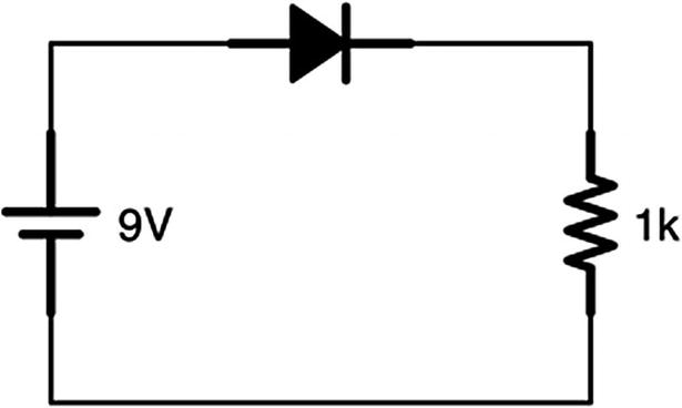
A Diode and Single Resistor Circuit
Therefore, our circuit will use 8.4 mA of current. So, as you can see, when doing calculations, the diodes simply provide a drop in voltage, they do not limit (or even affect) current.
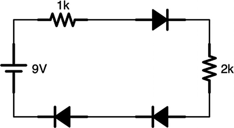
A Circuit with Multiple Diodes and Resistors
Therefore, we will have 1.8 V taken up by diodes, which drop voltage without limiting current. Since we have a 9 V source, there will be 9 − 1.8 = 7.2 V that is not eaten by diodes. This voltage will go to our two resistors. These resistors, even though they are separated by diodes, are essentially in series with each other. Therefore, we can treat them as a single resistor in series. So the total resistance on the circuit will be 1k + 2k = 3k Ω.

However, it is possible to put too many diodes in your circuit. Since they each eat 0.6 V in their forward voltage drop, that puts a limit on how many you can string together in series from a given battery. For a 9 V battery, if I try to put 20 diodes together in series, I will have used more than the total 9 volts that I have available. Therefore, current will not flow. With 20 diodes, the voltage drop will be 20 ∗ 0.6 = 12 V. Since this is more voltage than the battery can put out, no current will flow.
So we have seen two conditions for which current will not flow through a diode—the first is that the diode will block current from flowing in the wrong direction, and the second is that the diode will not conduct if the voltage source cannot provide enough voltage to bridge the forward voltage drop of the diode.
8.3 Circuit Calculations with Diodes in Parallel
The real magic of diodes comes when using them in parallel circuits. Remember the rules that we learned in Chapter 7. Kirchhoff’s voltage law says that between any two points, the voltage drop between those two points will be the same no matter what path the current follows. Therefore, since the voltage drop across a diode is fixed, that means that we can guarantee a maximum voltage drop between two points on a circuit by putting diodes between them.
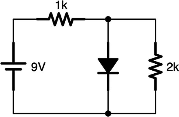
A Single Diode in Parallel with a Resistor
Kirchhoff’s voltage law tells us that no matter what path is traveled, the voltage difference between those two points will be the same. Since the 2k resistor is attached to the same two points that the diodes are attached to, Kirchhoff’s voltage law tells us that the voltage across the resistor must be the same as the voltage across the diode. Thus, the voltage across the resistor must be 0.6 V.

So how much current is flowing through the diode? To find this out, we need to use Kirchhoff’s current law. The amount entering the junction where the diode and the 2k resistor split off is the same as the amount leaving it. We know that 0.3 mA leaves the junction to go to the resistor. Therefore, if we could figure out how much current was coming into the junction, we could figure out how much is going through the diode.
To discover that value, we need to know how much current is going through the 1k resistor. To figure that out, we need to know the voltage drop across the resistor. However, we can figure this out easily. Since the tail end of the diode is connected to ground (the negative terminal), that means that after the diode, we are at 0 V. Therefore, since the diode voltage drop is 0.6 V, then the voltage before the diode must be 0.6 V. That means that the rest of the voltage must have been consumed by the 1k resistor.

In this circuit, there is 8.4 mA going through the first resistor. That means that there is 8.4 mA coming into the junction. We know that 0.3 mA is going out of the junction through the 2k resistor. That means that the rest of the current is going through the diode. Therefore, we can calculate that the current going through the diode is 8.4 − 0.3 = 8.1 mA.
Diodes don’t make the math harder, but they do force you to think a little harder about how you apply the rules.

A Circuit with Multiple Diodes
It is almost always easiest to analyze circuits starting with the diodes because their voltage drops are fixed. If we look at this circuit, the diode at the end gives the circuit a voltage drop of 0.6 V.
Now let’s look at the parallel part of the circuit. Here, we have three pathways—one through two diodes and two other pathways through resistors. However, one of the pathways contains all diodes. We know that diodes give a constant voltage drop, and we know that Kirchhoff’s voltage law says that all pathways between two points have the same voltage drop. Since we have two diodes, the voltage drop of this parallel pathway is 0.6 ∗ 2 = 1.2 V.

However, we technically don’t even need that number, because, since we already know the voltage drop across each resistor (it must be 1.2 V because of Kirchhoff’s voltage law), we can just apply Ohm’s law to each resistor.


The total current going into both resistors is simply the sum of each of the currents, 0.4 + 0.6 = 1.0 mA. So there is 1 mA total flowing through the two resistors. To find out how much current is flowing through the diode, we will need to know how much current is coming into the circuit itself out of the first resistor.

Therefore, we have 7.2 mA flowing through that first resistor. So, if we have 7.2 mA coming into the parallel circuit in the middle and 1 mA flowing to the resistors, the amount of current flowing through the diodes down the middle is 7.2 − 1 = 6.2 mA. The amount of current going through the final diode is the full 7.2 mA of current in the circuit.
Again, there are a lot of steps, but none of the steps are individually very hard. You simply start with the easiest-to-find values (in this case, the voltage drops from the diodes) and work out from there.
8.4 Diode Short Circuits
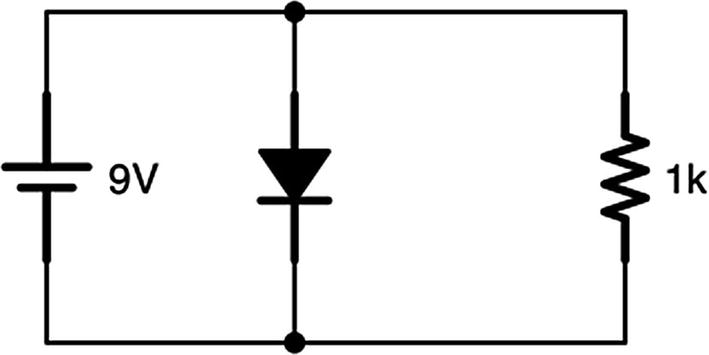
A Bad Diode Circuit

Thus, having a diode going direct from the positive to the negative of your voltage source is essentially the same as a short circuit. That is why the circuit is bad! To use a diode, there must always be resistance somewhere in series with the diode in order to dissipate the current from the excess voltage. The resistor can be before the diode or after it, but it must be there to absorb the extra voltage.
Additionally, it is important to make sure the amount of current flowing through your diode is within the specifications of the diode you are using. Most LEDs, for instance, are only rated for small currents up to about 30 mA.
8.5 Nonconducting Diodes

Nonconducting Diodes
In this figure, the voltage drop across the center diode bridge is 0.6 + 0.6 + 0.6 + 0.6 = 2.4 V. However, the battery source is only 1 V. Since the voltage drop of the diodes is larger than the available voltage, this part of the circuit is basically turned off. In reality, there is a small but ignorable leakage current (about 0.00000022 mA in this case if you were really curious), but we can think of this circuit as effectively switched off.
So keep that in mind—if you ever wind up with more forward voltage drop from a diode than you have available voltage, you may treat the diode as if it were an open (i.e., unconnected) circuit, as if it were not even there.

8.6 Usage of Diodes
Diodes can be thought of as circuit traffic cops—they regulate the flow of electricity. They make sure that everything within a circuit is happening in a controlled manner. They regulate the circuit in two different ways—by limiting the direction of current and, in parallel circuits, by establishing fixed voltages between two points.
The simplest usage of a diode is to use it as a device that makes sure that your battery is plugged in the right orientation. If you have a device that will be damaged if someone puts the battery in backward, a simple diode will make sure that the current can only flow in one direction.

A Simple Diode Protection Circuit
Another problem often solved by diodes is voltage regulation. Because diodes provide a fixed voltage drop between two points, you can use diodes to ensure a fixed voltage for devices that require it.
For instance, when we looked at batteries in Chapter 6, we noted that their voltage actually varied quite a bit. A 9 V battery might give you anywhere from 7 V to 9.7 V. This is true of any battery, not just the 9 V variety. In that chapter, we showed how we could use a voltage regulator to accomplish this, but a similar effect can be accomplished with diodes. If you need a fixed amount of voltage, you can use diodes to provide that at the cost of some extra current.
This isn’t recommended for a whole project (the excess current can generate a lot of heat), but sometimes makes sense in limited circumstances. However, for demonstrating the concept, let’s look at what it would take to provide voltage regulation using diodes.
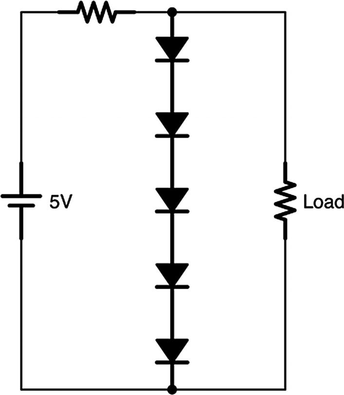
A Simple 3 V Voltage Regulator
Because the diodes provide a fixed voltage drop of 0.6 V each, then that pathway has a total voltage drop for five diodes of 5 ∗ 0.6 = 3.0 V. Kirchhoff’s voltage law says that between two points, every pathway between them will have the same voltage drop. This means that the load, since it is connected to those two points, will have the same voltage drop, thus regulating the amount of voltage used by the load.
But what about that first resistor at the beginning of the circuit? Remember, if we provide a pathway through diodes only, we create a short circuit in the system. There has to be some element (usually a resistor) that eats up whatever voltage is left over. Therefore, putting a small resistor before our diode pathway will give the circuit a place to use the excess voltage and limit the amount of current that flows.
The size of the resistor will depend on how much current the load requires and how much current you are willing to waste. A small resistor wastes more current, but allows for a higher maximum current used by the load. A larger resistor wastes less current, but if the load needs a lot of current, it could interfere with the voltage regulation.


This is much better—we are only using 4 mA in this circuit, so we are only wasting 1 mA. There has to be some amount of waste to do the voltage regulation.

Here, the current is only 2 mA, but we need 3 mA to power the circuit! Thus, if we use a 500 Ω resistor, we can’t handle our power supply dropping down to 4 V.

So, here, the 20 Ω resistor will still provide plenty of excess current to allow our regulator to keep working. However, it is still eating up an extraordinary amount of current compared to our load.


So, at full charge, there is 7 mA going through this resistor, which means we will waste 4 mA. Whether or not that is acceptable to your circuit depends on what you are going to do with it!
Note that there are better means of regulating battery voltage for a whole circuit than using diodes. However, many times you need a regulated voltage somewhere within a more complex circuit. Diodes are great for that, and the same calculations and considerations apply.
One final note: As mentioned earlier, although we think of diodes as providing a fixed voltage, they actually do vary a little bit with the amount of current flowing through them. In any circuit, you should allow for ±10% variance in the voltage drop of a diode.
8.7 Other Types of Diode Protection
Diodes can provide other types of protection for circuits as well. As single-direction control valves, they can be used to prevent a variety of overvoltage conditions. Oftentimes they are wired in such a way that they will not normally conduct, but will conduct under certain conditions to redirect extra voltage in a safe manner.
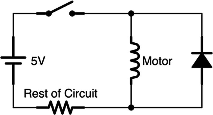
A Diode Protection Circuit
To protect the rest of the circuit from this sudden influx of voltage, the diode provides an alternative path back through the motor. Thus, when the voltage starts to build up after the switch closes, the diode provides a safe pathway back through the motor for it to flow, allowing the voltage buildup to slowly dissipate through the motor, rather than overloading a circuit expecting 5 V with 50 V.
Oftentimes when looking at circuit diagrams, you may find diodes in funny places and oriented in funny ways. These are oftentimes providing some sort of protection to the circuit from potential failure conditions or exceptional circumstances. Many microchips, for instance, use diodes to shunt off excess voltage from static electricity shocks.
8.8 Zener Diodes
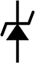
The Zener Diode Schematic Symbol
Remember that most diodes have a breakdown voltage if you try to pass voltage the wrong way. However, in most diodes, this is a failure mode—doing this can, at best, be unpredictable, and, at worst, damage your diode. A Zener diode, however, is built so that it has a very predictable operation at its breakdown voltage. In fact, at its breakdown voltage, it acts like a normal diode with a larger voltage drop.
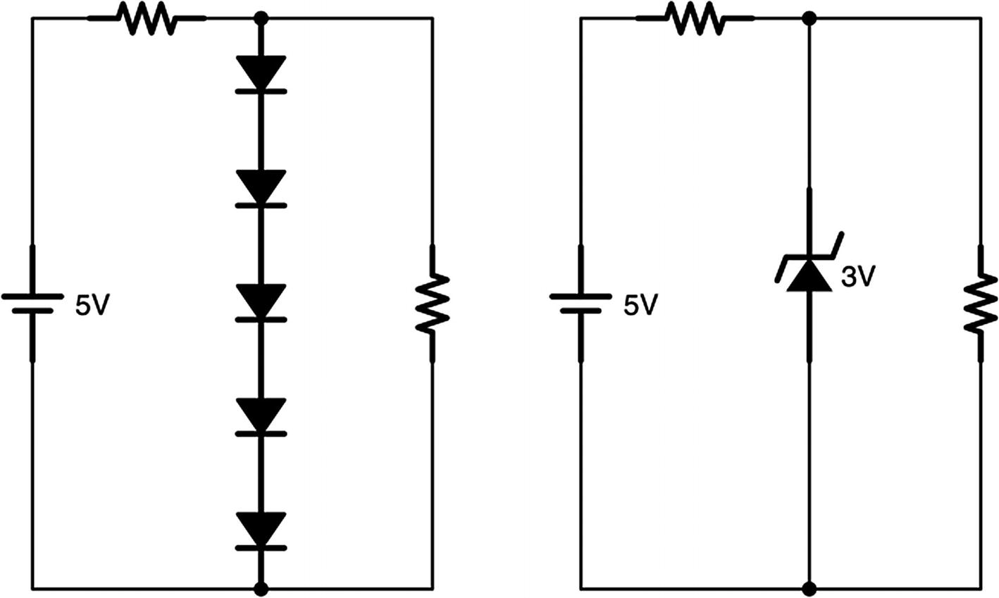
A Circuit Regulated by Regular Diodes and a Zener Diode
Not only that, the breakdown voltage drop for a Zener diode is much more constant over a larger range of current than the forward voltage drop of most regular diodes. Because of this, Zener diodes are used much more often for voltage regulation than a series of regular diodes.
Zener diodes come in a variety of breakdown voltages. In any exercise in this book which involves drawing a circuit with a Zener diode, you may presume that the Zener diode with the voltage drop you are looking for exists. When drawing a circuit, be sure to label the Zener diode with the breakdown voltage you are needing.
8.9 Schottky Diode
A Schottky diode is very similar to a normal diode, but it is made using a different process, meaning that its voltage drop is significantly reduced. While a “normal” diode’s forward voltage drop is about 0.6 V, a Schottky diode’s voltage drop can be as low as 0.15 V. This can be very useful in cases where a diode is needed to regulate the direction of electrical flow, but the voltage requirements are sensitive enough that you can’t afford the 0.6 V of a regular diode.
8.10 Diode-Like Behavior in Other Components
Another important reason for being familiar with diode operation is that other types of components have parts which contain diodes or behave in diode-like ways. When we discuss bipolar junction transistors (BJTs) (see Chapter 24), we will see that these components partially consist of diode-like behavior.
8.11 Review
- 1.
Diodes only allow current to flow in one direction.
- 2.
Diodes have a fixed forward voltage drop across the diode—0.6 V for normal diodes and a range of about 1.8 to −3.3 V for LEDs.
- 3.
Different color LEDs have different voltage drops.
- 4.
Diodes also have a breakdown voltage—the amount of voltage for which, if applied in the reverse direction, the diode will no longer block current.
- 5.
When analyzing circuits with diodes, it is often easier to analyze the diodes first, since the voltage drop is fixed.
- 6.
Because of Kirchhoff’s voltage law, anything wired in parallel with diodes will have the same voltage drop as the diodes (or possibly less).
- 7.
If the forward voltage drop on a diode is greater than the available voltage in the circuit, the diode will not conduct, and it can be treated as an open circuit.
- 8.
If diodes are connected to the positive and negative terminals of a voltage source (such as a battery) with no resistance in series, this will create a short circuit, causing extremely large amounts of current to flow through the diodes.
- 9.
Diodes are often used as control valves to regulate the direction of current flow on a circuit.
- 10.
Diodes are often used to regulate the amount of voltage between two points on a circuit.
- 11.
The series resistor used with voltage-regulating diodes determines both how much current is wasted and how much current the load can draw—lower-value resistors waste more current but allow the load to draw more current, and higher-value resistors waste less current but don’t allow as much potential current to your load.
- 12.
When designing circuits, it is often useful to account for the most extreme variations possible. This will allow your circuit to be more flexible.
- 13.
Diodes can also provide protection to circuits against strange failure conditions, such as voltage spikes and static electricity. Diodes in strange places in circuit diagrams are often there to protect the circuit against certain types of failures or events.
- 14.
Zener diodes are built so that they have very reliable operation on their breakdown voltage.
- 15.
Wiring a Zener diode backward gives you the equivalent of several forward diodes in series and can be used for simple voltage regulation.
- 16.
The breakdown voltage of a Zener diode is much more constant than the forward voltage of a regular diode and therefore works even better for voltage regulation.
- 17.
Zener diodes come in a wide variety of breakdown voltages and are usually labeled on the circuit with the necessary breakdown voltage.
- 18.
Schottky diodes are like ordinary diodes except they have a much smaller forward voltage.
- 19.
Understanding diode behavior is important because a number of components contain diodes or exhibit diode-like behavior.
8.12 Apply What You Have Learned
- 1.
If you have a 9 V voltage source, a blue LED, and a 500 Ω resistor all in series, how much current is running through the LED?
- 2.
If you have a 3 V voltage source and a red LED, what size resistor do you need to put in series with the LED to have it use 3 mA of current?
- 3.
If you have a 10 V voltage source, a blue LED, a red LED, and a 200 Ω resistor all in series, how much current is running through the LEDs?
- 4.
If I have a 12 V voltage source, a blue LED, and a red LED and the LEDs have a maximum current of 30 mA before they break and a minimum current of 1 mA before they turn on, what range of resistors can I put in series with the LEDs to get them to light up without breaking?
- 5.
In the following circuit, calculate how much current is flowing through each component and each component’s voltage drop if R1 is 500 Ω (note that the diode is just a regular diode, not an LED).

- 6.
Let’s say instead of an ordinary diode, the diode is a blue LED. Recalculate the current going through each component and the voltage drops for each component.
- 7.
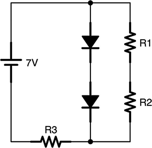
In the following circuit, calculate how much current is flowing through each component and each component’s voltage drop if R1 is 300 Ω, R2 is 400 Ω, and R3 is 500 Ω.
- 8.
Draw a circuit that provides a 6-volt regulated power supply to the circuit load from a 9-volt battery using regular diodes. Choose a resistor that works efficiently for a circuit load of 500 Ω and operates with a battery voltage from 7 V to 9.6 V. What is the current at the lowest and highest ranges of the battery? How much is used by the circuit load, and how much is wasted through the diodes in each configuration?
- 9.
Draw an equivalent circuit to the previous question using a Zener diode instead of normal diodes.