
In Chapter 12, we learned the basics of digital logic. However, I think we can all agree that those chips wound up taking up a lot of space on our breadboards. If we wanted to do a lot of complicated tasks, we would wind up needing a lot of chips, we would need more and more breadboards to put them on, and our project would get unwieldy very quickly. Additionally, as the number of chips increased, it would get very expensive to build such projects.
Additionally, when all of the logic of a circuit is hardwired into the circuit through logic chips, it is very difficult to change. If you need to change the logic (convert an AND gate to an OR gate or do anything else), you wind up needing to wade through masses of circuitry to make the change you want. Then, if you are mass-producing the circuit, you have to set up for mass production all over again.
To solve all of these problems (and more), the microcontroller was introduced. A microcontroller is essentially a low-power, single-chip computer. A “real” computer chip usually relies on a whole slew of other chips (memory chips, input/output chips, etc.) to operate. A microcontroller contains all of these (though usually on a smaller scale) in a single chip that can be added to an electronics project.
Unlike your typical computer, most microcontrollers can’t be connected to a mouse, keyboard, or other typical inputs and can’t be connected to a monitor, disk drive, or other typical outputs. Instead, microcontrollers usually communicate entirely through digital (true/false) electrical signals on their pins.
So, instead of wiring complex logic onto their boards, many people opt to have microcontrollers provide the bulk of their digital logic. One complication that this adds, however, is that since the microcontroller is essentially a computer, then just, like a computer, it has to be programmed. This means that not only must circuit designers be familiar with electronics, they must also be familiar with computer programming.
13.1 The ATmega328/P Chip
The microcontroller we will be focusing on is the ATmega328/P. Actually, we will focus less on this specific chip than the overall environment surrounding it, known as Arduino (we will cover more of what this means in Section 13.2, “The Arduino Environment”).
Even though the Arduino environment tries to minimize how much you have to know about the hardware itself, it is good to have a quick introduction to this chip and how it works.
The ATmega328/P is part of a family of microcontrollers developed by Atmel known as the AVR family. The AVR became popular because it was one of the first chips to use flash memory to store its programs, which allowed the onboard programs to be more easily changed.
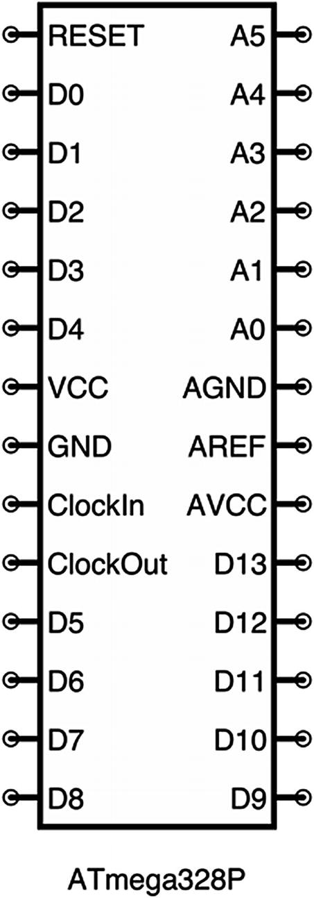
A Simplified Pinout of the ATmega328/P
All of the pins labeled “D” are digital input/output pins. They can be configured as inputs for buttons or other signals or as outputs for driving LEDs or other output devices. The pins labeled “A” are analog input pins (we will cover how to use these in Chapter 15). While the digital input pins can only read that a value is true/false, the analog pins can read voltages and convert them to numbers. AREF is a “reference voltage” used for setting the maximum voltage for analog inputs, but is usually unconnected (it should also not be a higher voltage than AVCC).
Microcontrollers, like most processors, control their operation by using a “clock.” This is not a clock as you normally think of—it doesn’t tell time. Instead of thinking of it as a clock, a better way to think of the “clock” is as a heartbeat. Basically, there is a continuous signal of pulses that are provided through the clock, and the pulses allow the chip to synchronize all of its activities. The ATmega328/P has an internal clock, but it can also be more efficiently operated by connecting an external clock (quartz crystals, for instance, provide a very steady pulse for this purpose).
As we have noted, the chip has a number of input and output pins. You might wonder, what does the chip do with its input and output pins? That is entirely up to you. It does whatever you program it to do. The ATmega328/P has flash memory on the chip which can store a computer program (flash memory means that it will remember the program even after the power turns off). You have to upload your program to the chip, and then after that, it will do whatever you like with its inputs and outputs. The D0 and D1 pins, in addition to providing input and output, can also be used to reprogram the chip. We will learn how to program the chip in Section 13.4, “Programming the Arduino.”
13.2 The Arduino Environment
The chip itself is just one piece of the puzzle. In order to use the chip, you have to be able to program it. Programming requires the use of programming tools on your main computer. In addition, you also need some way to take the program that you built on your computer and load it onto the chip. That takes both software and hardware.
Then, once the program is on the chip, you have to build a circuit to properly power the chip. This requires voltage regulation for the VCC pin and several other recommendations from the manufacturer about how to set up the other pins. To make it run optimally, it would also be good to supply an external clock. All of this can be quite a lot of work, and a lot of pieces that need to be brought together.
Thankfully, most chips have what is called a development board that can be purchased. A development board is a prebuilt circuit that has a microcontroller chip pre-connected in its recommended manner. It is made to simplify the work of developing circuits. Likewise, most chips have a recommended programming environment as well. A programming environment is a set of tools for your computer that allow you to create programs for your microcontroller. Additionally, a device called an in-system programmer (ISP) connects your computer to your chip or development board and will transmit the program from your computer to the chip.
In 2005, a complete, simplified system for doing all of these tasks called Arduino was created, based off of an earlier system called Wiring. Arduino consists of (a) a simplified development environment for your computer to write software for microcontrollers, (b) a simplified development board to make it very easy to build electronics projects, and (c) integrating the in-system programmer into the development board so that all that is required to transfer the program to the microcontroller is a USB cable.
The Arduino environment supports a number of different microcontroller chips. Because it is a simplified environment, many of the special features of individual chips are not directly supported. However, for getting started and doing basic projects, the Arduino environment is excellent.
Even though there is a company behind Arduino, there are many Arduino-compatible boards made by other manufacturers. These boards use the same ATmega328/P microcontroller and often have very similar development boards and functions. Most importantly, they are compatible with the programming tools on the Arduino environment.1
13.3 The Arduino Uno

The Major Components of the Arduino Uno
The Arduino Uno provides chips for power regulation, USB communication, as well as the ATmega328/P microcontroller itself. It also supplies an external clock for the microcontroller. Finally, it provides headers (places on the board to plug in wires) for the major pins on the microcontroller. Thus, everything you need to make use of the chip is provided for you in this development board. You simply connect the input and output pins to your own breadboard, and you can have a working project that you can program.
13.4 Programming the Arduino
Now that we have seen the pieces of the Arduino environment, let’s tackle programming the Arduino. This book is not a book about programming, so we will only cover the absolute basics.
The programming tool for the Arduino is called the Arduino IDE . IDE stands for “Integrated Development Environment”—in other words, the thing that you develop with. The Arduino IDE is available for pretty much any computer—Mac, Windows, or Linux. You can download the IDE from http://arduino.cc/.
Depending on whether you purchased an “official” Arduino or a clone, you may also have to download an additional driver for the USB interface. If you have an Arduino-compatible clone, you can download the driver from http://bplearning.net/drivers. Once you have installed the Arduino IDE and the USB driver, you are ready to start!
We will begin by using an example program (called a “sketch” in Arduino terminology) that ships with the Arduino. First, connect your Arduino to your computer with a USB cable. Open up the Arduino IDE; then click “File,” then “Examples,” and then “01.Basics”; and finally click “Blink.” This loads up a ready-made program for your Arduino. This program simply turns the D13 pin on and off. On an Arduino, the D13 pin already has an LED attached to it, so you don’t even need to add any components!
Now that you have the program loaded up, click the button with the checkmark icon. This verifies that the program is written in a way that the computer can understand. If it has any errors, it will show them in the black panel on the bottom.
Now you need to make sure that the IDE is targetted at your board. Go to “Tools” and then “Board” and make sure that “Arduino/Genuino Uno” is selected. Then, click “Tools” and then “Port” and make sure your Arduino was detected and that it is selected. If you don’t see your Arduino listed here, you may need to check the USB driver installation.2
Once your configuration is verified, click the button with the arrow icon to upload it to the Arduino. It should take about 2–5 seconds, and then the LED on your Arduino should start blinking. If there are any errors, they will display in the black status area below. Note that some Arduinos come with this program preinstalled. If this is the case, your Arduino may not have changed what it is doing much. You can verify that it is all working by changing the program slightly. If you change all of the numbers that say 1000 to 500, it should blink twice as fast. Remember, though, that you must verify it (click the checkmark button) and upload it (click the arrow button) to get your new code onto the board.
Now, let’s take a look at the code and how it functions. The first part of the code should be grayed out. That’s because it is a comment, or a note telling you about the program. This isn’t read by the computer at all. Comments start with the characters /*, and they continue until they reach the characters */ (this can even span multiple lines). Shorter comments are sometimes made with the characters //. Those comments only continue until the end of the line.
After the comments, there are two functions defined—setup() and loop(). A function is simply a piece of code that is named. In the Arduino environment, the setup and loop functions are special. The setup function runs exactly once when the chip first turns on or resets or when a new program is loaded. It is used for things such as telling the chip which pins will be used for input and which ones will be used for output and doing other setup-related tasks. After the setup function completes, the loop function runs continually over and over again for as long as the chip is on.
This tells the microcontroller that digital output 13 (D13) will be used for output. Note that this refers to the D13 pin in Figure 13-1 (usually just labeled 13 on the Arduino Uno), not to pin 13 of the chip itself (which would be D7). With the Arduino Uno, we don’t actually need to worry about the pinout of the ATmega328/P, we just need to read the names of the pins next to the pin headers.
The first line, digitalWrite(13, HIGH);, says to turn D13 to HIGH, which is about 5 V. This provides the power for the LED attached to D13. This pin will remain high until we tell it to do something else.
The next line, delay(1000);, tells the chip to wait for 1,000 milliseconds (which is 1 second). During this time, nothing happens—the chip just waits. Changing this number changes the amount of time that the chip will wait for. Changing it to 500 will cause it to wait for half a second, and increasing it to 2000 (note that there are no commas in the number!) will cause it to wait for 2 seconds.
The next line turns D13 to LOW/false/off/0 V. This turns off the LED, because there is no longer any voltage supplied to it. D13 will stay in this state until told otherwise. The next line then waits for 1 second. Once this function finishes, the chip will simply run the loop function again from the start.
In Chapter 14, we will look at how to build projects with the Arduino that use additional components.
13.5 Review
- 1.
A microcontroller is a small computer in a single microchip that provides customizable logic for handling digital signals.
- 2.
A development board is a circuit board that simplifies the process of building circuits with a microchip by providing most of the standard connections for you, allowing you to focus your efforts on the things that make your project distinctive.
- 3.
In order to use a microcontroller, it has to be programmed from a computer.
- 4.
The Arduino environment is a combination of software and hardware meant to make building microcontroller projects easier.
- 5.
The Arduino Uno is a development board for the Arduino environment that includes a microcontroller, USB connection, power regulation, and headers for connecting the microcontroller’s input/output pins to other circuits.
- 6.
The ATmega328/P is the microcontroller used in the Arduino Uno.
- 7.
An Arduino program (called a sketch) has two standard functions—setup (which is run once when the chip powers on) and loop (which runs over and over again as long as the chip is on).
- 8.
Once a program is uploaded to the Arduino Uno, it will be saved on the device until another program is loaded.
13.6 Apply What You Have Learned
- 1.
Practice modifying and uploading the Blink program to the Arduino Uno. Change the numbers given to delay to different values, and see how that affects the operation of the program.
- 2.
The ATmega328/P is only one of many different microcontrollers available in the AVR family. Research online to find one or two other AVR chips and what different features they have.
- 3.
The AVR family is only one of many microcontroller families. Research one or two other microcontroller families and look at what features are claimed for each. Examples of other microcontroller families include PIC, STM32, MSP432, and the Intel Quark.
- 4.
Go to the arduino.cc website and look at the different types of Arduinos that are available. What makes them different? Why might you choose one for a project over another?