- 1.
Requirements gathering
- 2.
Creating the requirements document
- 3.
Gathering hardware
- 4.
Configuring the hardware
- 5.
Writing the software
- 6.
Debugging the Arduino software
- 7.
Troubleshooting the hardware
- 8.
Finished prototype
As you can imagine, even this summary of the engineering process is very effective when prototyping, which is why we will use it with the Arduino in this book. What is the Arduino? The Arduino is a very customizable microcontroller used by hobbyists and engineers alike. Also, it is open source, which means that the source code is available to you for your programming needs; the integrated development environment (IDE) (where you will be writing your software) is free, and most resources you can find are open source. The only thing you have to buy is the Arduino microcontroller itself. The Arduino is supported very well on the Web and in books, which makes it very easy to research how-to topics; a few sites that will help you get started are www.arduino.cc and http://tronixstuff.wordpress.com/tutorials/. But this book is more than simply a how-to reference; this book is going to teach you the engineering process—a skill that is useful for making projects more readable, efficient, and reliable. This book will also focus on end to end development, another useful skill (or skills as the name implies) that will allow you to create robust prototypes and/or fully developed hardware and software, but first we will take a look at the engineering process.
Gathering Your Hardware
Arduino : Since the first edition of this book, there have been many new developments in the Arduino product line (a lot from other vendors as well); there are many flavors of the “Arduino” out in the wild. For the purposes of this book, the MEGA 2560 Pro will be used. This is because it has a very small form factor, and it has a ton of IO (inputs/outputs). Really though as we are designing through this book, you may want to experiment with other Arduino boards; that is fine and encouraged since most of the code in this book will work with the standard Arduino UNO form factor; that is not to say other form factors will not work as well. See Figure 1-1.

1. Arduino Pro Mini, 2. MEGA 2560 Pro, 3. Bluetooth Arduino, and 4. Arduino UNO
Bluetooth Mate Silver or RN-42: Since this book will focus on end to end development while still keeping in mind the engineering process to prototype your circuit, you may want to purchase a Bluetooth Mate Silver, but when we design actual PCBs (Printed Circuit Boards), we will need to use a module that we can quickly and effectively use just like the Bluetooth Mate Silver, which is the RN-42. This module has a small footprint which will be nice because we want to use as little space on the PCB as possible. See Figure 1-2.

1. RN-42 Bluetooth Module, 2. Bluetooth Mate Silver
Solderless breadboard: Another very important piece of hardware is the solderless breadboard (see Figure 1-3), which is used to implement your circuitry. For this book, you need to have a midsize solderless breadboard. It will be used in both the design and troubleshooting phases of the projects and will allow you to create a proof of concept for when we create the PCB in Eagle.
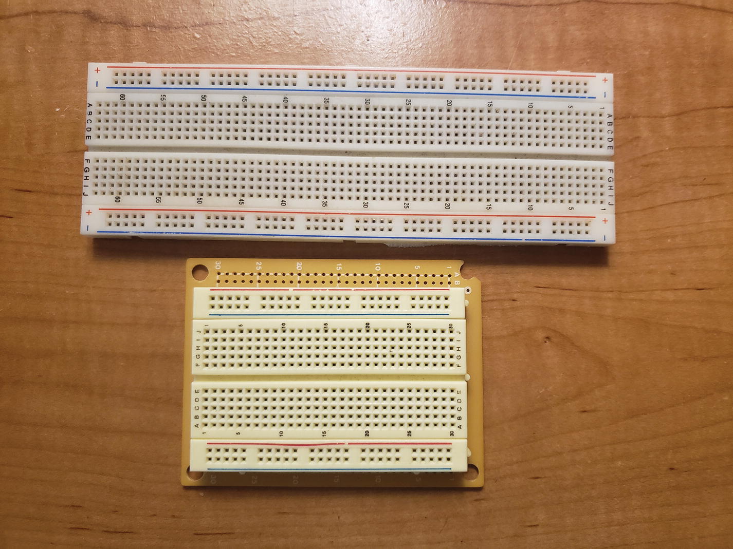
An example of some solderless breadboards
Wire: We will use a large quantity of wire in this book; you can get a wire jumper kit at almost any electronics store.
Arduino shields : Unlike the first edition of this book, we will not focus too much on shields; they are very useful and can make validating firmware a breeze, but this edition will focus on creating a couple of shields for the MEGA 2560 Pro. See Figure 1-4 for a couple of examples of shields, and underneath that picture, you will find a few descriptions of useful shields for this book. Please note that it is not necessary to purchase these shields, but they are still valuable tools.
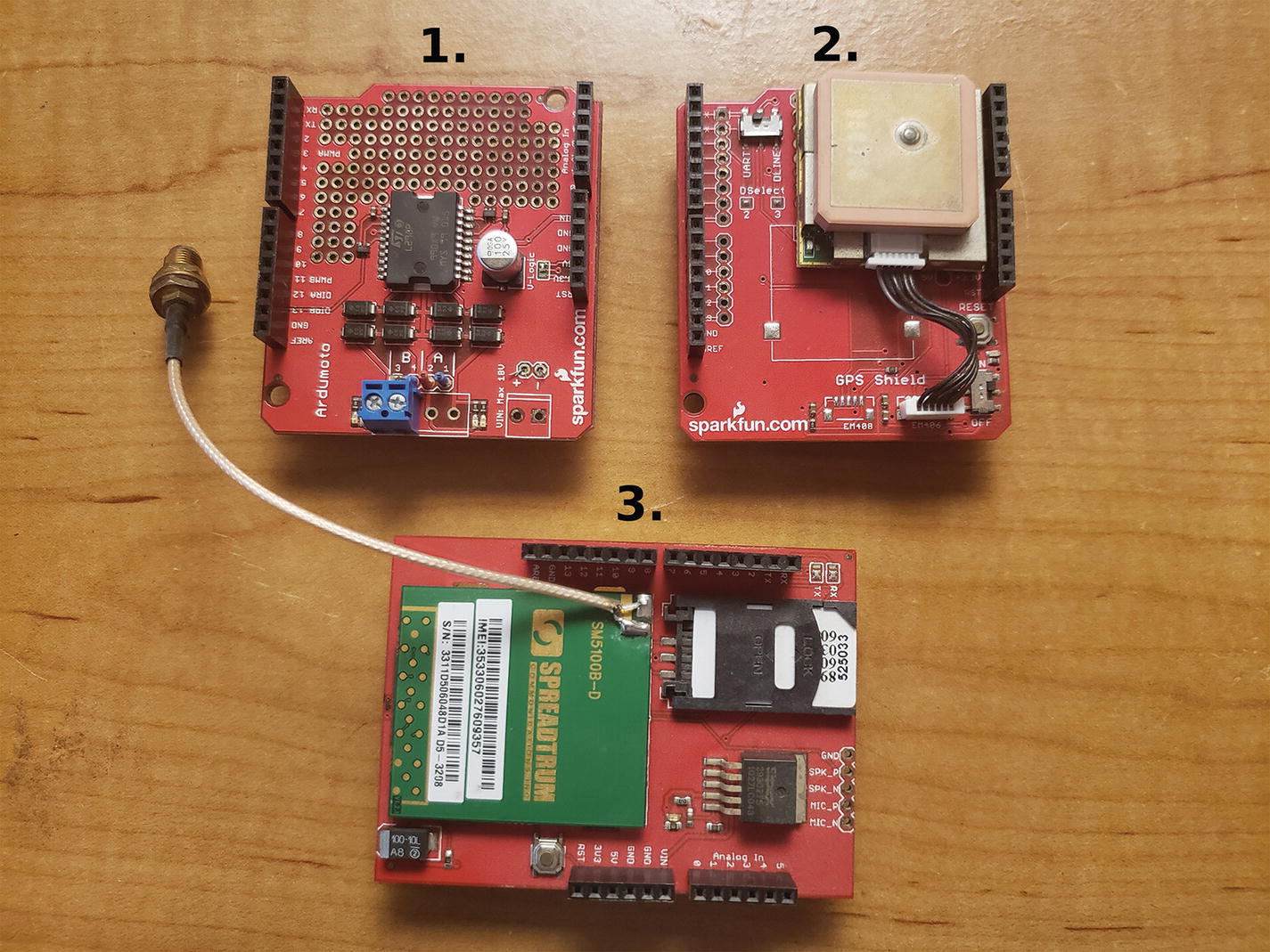
1. Motor shield, 2. GPS shield, 3. GSM shield
Motor shield: This shield is used to control motors up to 18V. It includes a surface mount H-bridge, which allows for a higher power motor to be used as well as for control of two motors.
GPS shield: This shield is used to get positioning information from GPS satellites. It uses the National Marine Electronics Association (NMEA) standard, which can be parsed to tell you any number of things such as longitude and latitude, whether the GPS has a fix, what type of fix, a timestamp, and the signal-to-noise ratio.
Sensors: These are very important because they give your projects life. Some sensor examples are PIR (Passive Infrared), sonar, and temperature (see Figure 1-5).

1. GPS module with breakout board, 2. accelerometer, 3. photoresistor, 4. temperature sensor, 5. flex sensor, 6. PIR sensor, 7. tilt sensor, 8. humidity sensor, 9. FSR (force sensitive resistor)
PIR sensor: This is an outstanding sensor for detecting changes in infrared light and can detect changes in temperature. It is also great at detecting motion, and that’s what we will use it for.
Sonar sensor (not pictured): Sonar sensors are good at detecting objects in their surroundings. The sonar sensor we will use is a Parallax sensor that uses digital pinging to tell how far away an object is.
Temperature sensor: These sensors are used to read temperature. To use them, you first scale the voltage to the temperatures you want to record.
Accelerometer: This sensor can detect acceleration in multiple directions, that is, in the X, Y, and Z directions. There are accelerometers that have more degrees of freedom. These sensors can be used to measure motion, vibration, or shock. For example, accelerometers are used in Fitbits and other exercise tracking hardware to keep track of your step count or even what exercise you are doing. We will be using an accelerometer later in this book on the main shield that we will create.
GPS module: The GPS module that will be used in this book is the EM-506; it has a UART interface which will make it very easy to interface with the Arduino.
Photoresistor: These sensors are used to sense brightness and dimness.
Tilt sensor: This sensor is used to detect if a system has flipped over which can be useful if you don’t have access to an accelerometer.
Flex sensor: As this sensor is flexed, the resistance increases, which can then be read by the Arduino on one of its ADCs (Analog to Digital Converters) to keep track of how much flex a system has.
Humidity sensor: The RHT03 humidity sensor can read both temperature and relative humidity and is accurate (+/–2%RH for humidity and +/–0.5C for temperature) for a low-cost sensor.
FSR (force sensitive resistor): This sensor is great to detect force. A good use for this sensor may be a scale or to detect pressure points.
Servos and motors: We will be using motors and servos to control many aspects of the projects (see Figure 1-6).
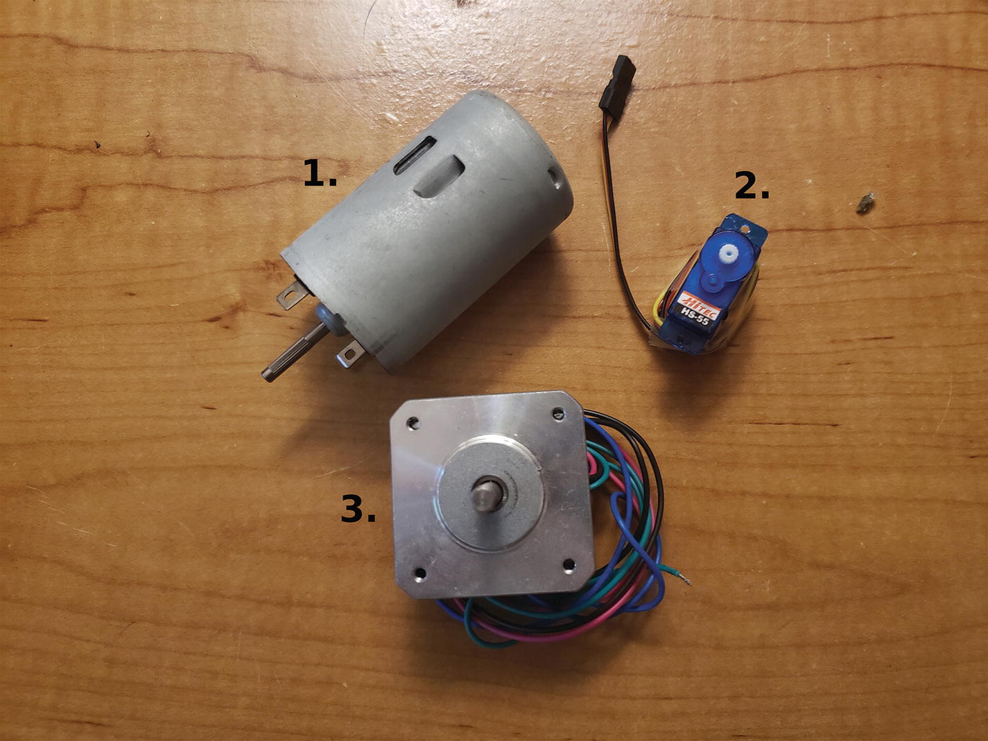
1. 12V DC motor, 2. 9g servo motor, 3. 24V DC pancake stepper motor
Miscellaneous: These are the most common components, such as resistors, capacitors, LEDs, diodes, headers, push buttons, and transistors. You can buy many kits that will supply you for a while on all this hardware at a low cost (see Figure 1-7).

Miscellaneous pieces of hardware (various terminal blocks/connectors, diodes, headers, push buttons)
Gathering Your Tools
You will also use a variety of tools; this section will briefly describe them. An (*) will be placed next to the hardware that is not required, but is a good tool to have.
Soldering iron: This tool is used to connect circuits to each other; we will use it mostly to connect wire to circuits (see Figure 1-8).
Solder: You will use this in conjunction with the soldering iron; it is the metal that connects the circuits together. Solder has a very low melting point.
Needle-nose pliers: These pliers are very important; they are used to hold wire and circuits in place, wrap wire around circuitry, and so on.
*Third hand: This is a very useful tool when you are trying to solder a PCB together (see Figure 1-12 #2).
Cutters : These are used to cut wires (see Figure 1-12 #1).
Wire stripper: This tool is used to take off wire insulation (see Figure 1-12 #3).
Multimeter: Possibly the most important tool you can own; this tool allows you to read voltage (AC (alternate current) and DC (direct current)), amps (ampere), and ohms (see Figure 1-10).
*Scientific calculator: This allows you to do various calculations (Ohm’s law, voltage divider, etc.).
*Adjustable DC power supply: With a power supply, you can give your projects continuous power; this is normally only used for testing circuits (see Figure 1-9).
*Microscope: Can be very useful for checking leads on circuits to make sure they are soldered properly (see Figure 1-11).
*Logic analyzer: Another very useful tool; a logic analyzer will read back data coming off of various IO lines. For example, the one pictured in Figure 1-13 #1 can read eight lines of IO simultaneously; these IO lines could be UART, I2C, SPI, and so on. We will discuss these protocols later in this book.
*AVR programmer (AVRISP mkII): This programmer can be used to upload code into various Atmel uC (microcontrollers). It is also able to upload the Arduino Bootloader onto the ATMEGA2560 or ATMEGA328p.
*FTDI programmer: Another programmer, if the board you are working on does not have an ISP (in-system programmer), it may have a five-pin header that you can connect an FTDI programmer to. Make sure you get the correct voltage level FTDI programmer for your system. Normally, they come in 5V and 3.3V levels (see Figure 1-14).
*Oscilloscope : The multimeter and the oscilloscope are probably the most important tools when debugging electronics. The Oscope, as it is sometimes referred to as, allows you to measure voltage vs. time. This can be useful when reading back digital or analog signals. For example, you may want to read the output of a digital pin to make sure it is triggering at the correct intervals. This is an example where a multimeter would not be as useful as an Oscope because the Oscope will show you voltage over time (such as transitions from high to low states) for a set interval, and the multimeter will just display the latest voltage output.
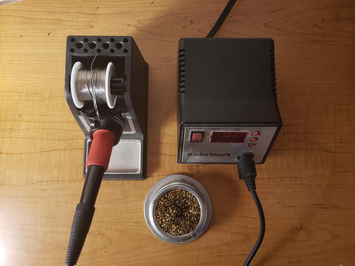
A soldering iron and its stand
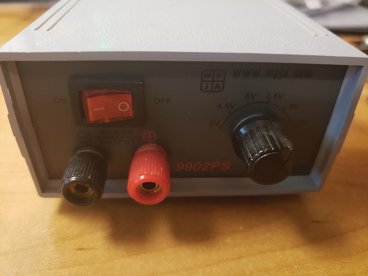
Adjustable DC power supply (3, 4.5, 6, 7.5, 9, and 12V)
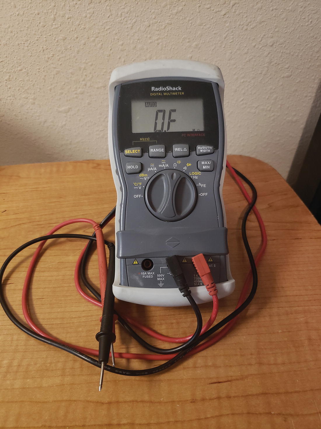
Multimeter
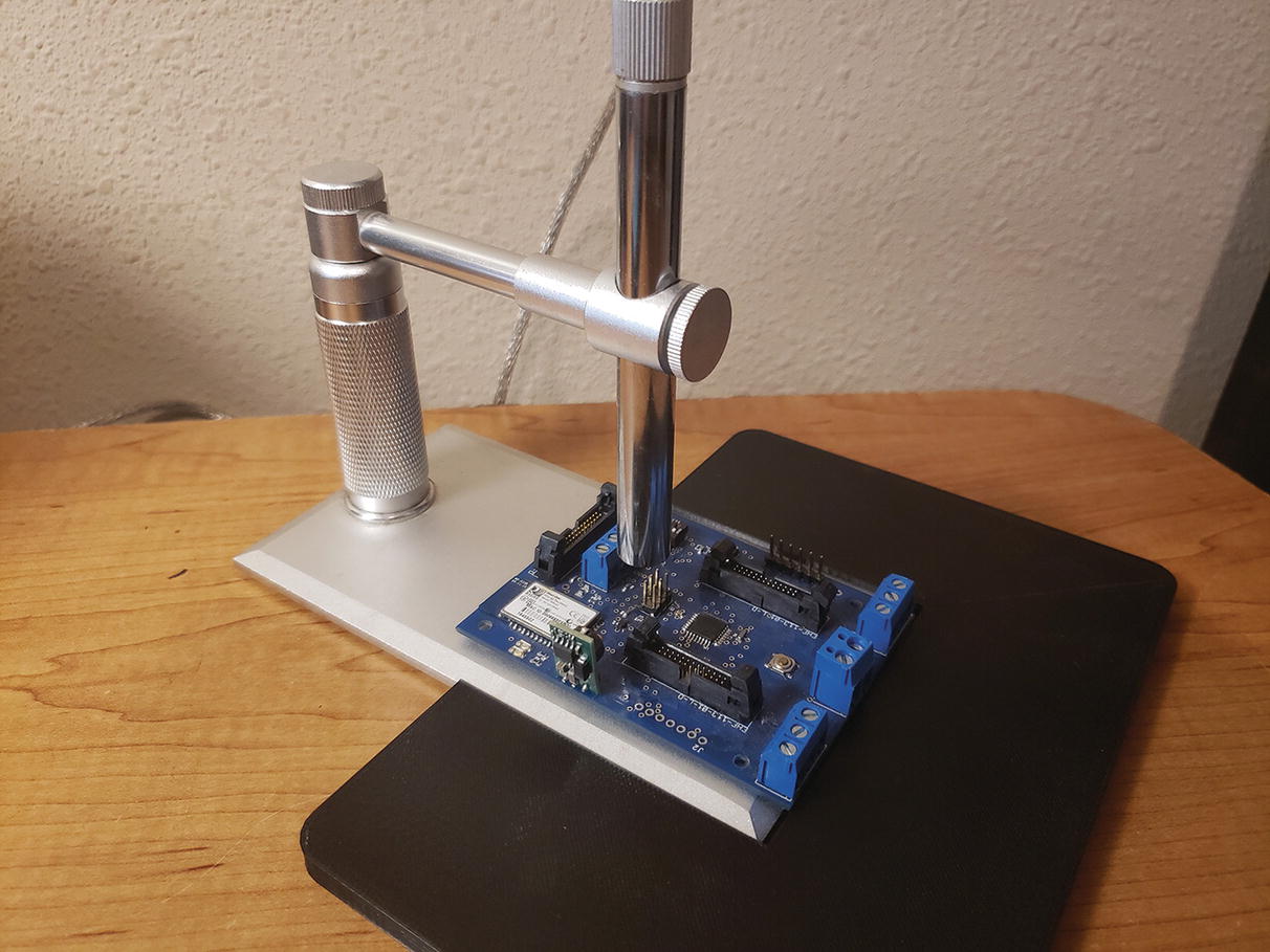
USB microscope
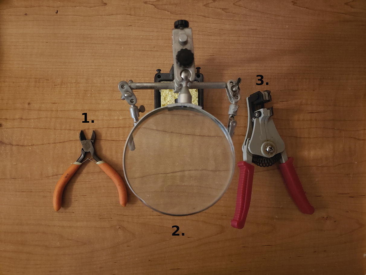
1. Cutters, 2. third hand with magnifying glass, 3. wire strippers
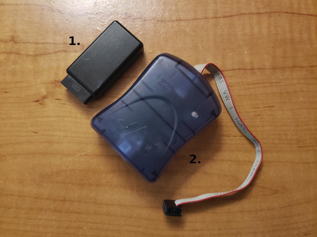
1. Logic analyzer, 2. AVR programmer AVRISP mkII
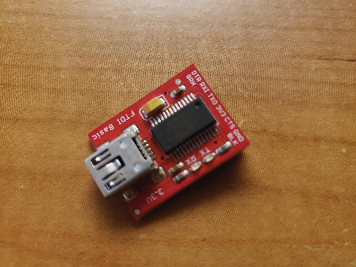
FTDI programmer
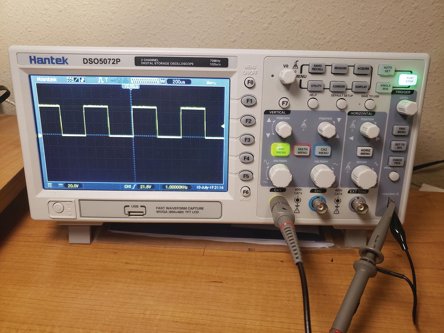
A two-channel 70MHz digital oscilloscope (note how the Oscope is displaying the high to low transitions 0 to 5V at a frequency of 1kHz and a 50% duty cycle)
Understanding the Engineering Process
The engineering process is very useful in making your designs more efficient, streamlined, and comprehensible. The process consists of gathering requirements, creating the requirements document, gathering the correct hardware, configuring the hardware, writing the software, debugging the software, troubleshooting the hardware, and the signing off on the finished prototype.
Requirements Gathering
One day, when you’re an engineer, you may be asked to go to a company and assess its needs for a particular project. This part of the engineering process is crucial; everything will depend on the requirements you gather at this initial meeting. For example, assume you learn that your client needs to blink an LED at a certain speed, and for that task, you and the client determine that the Arduino microprocessor is the best choice. To use the Arduino to blink the LED, a customer needs an LED to blink at 100ms intervals.
Creating the Requirements Document
- Hardware
Arduino
LED
9V battery
9V battery connector
330ohm resistor
- Software
A program that blinks an LED at 100ms intervals

Blinking LED processes
Gathering the Hardware
The next very important part of the engineering process is making sure you have the right hardware. Your hardware needs should be decided as you gather requirements, but it is important to make sure all your hardware is compatible. If it is not compatible, hardware changes may be necessary, but you should consult the company you are working with to make sure it is satisfied with any hardware changes.
Configuring the Hardware
Arduino
LED
330ohm resistor
USB cable
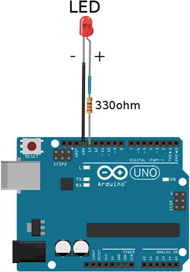
The hardware setup for the blinking LED project

Wiring guide for the Arduino LED project
Alright, now that the hardware is finished, we need to get the Arduino IDE software up and running on Windows. To do this, go to www.Arduino.cc/en/Main/Software. The Arduino IDE will work with Windows 8 or 10 (it will even work with older versions of Windows as well), Mac OS X, and Linux systems. After the Arduino IDE is downloaded to your desktop, it will be in a zipped format, so unzip the Arduino folder to your desktop. The Arduino IDE is now installed.
Now that you have the Arduino IDE installed on your computer, you need to make sure it is configured correctly. To do this, open the Arduino IDE, and go to Tools ➤ Port; select the serial port your Arduino is connected to. Next, select Tools ➤ Board, and select the Arduino board you are using; for this project and this project only, we will use the Arduino UNO. Later projects will use the MEGA 2560 Pro board. Once your hardware is configured, it is time to write the software.
Writing the Software
When you try to compile this program to your Arduino, it gives you an error. This is because of a syntax error that we will debug in the next section.
Debugging the Arduino Software
Syntax errors are not the worst errors out there. The worst errors you can receive are logical errors; these errors allow the code to compile, but the end result is unexpected. For example, using a greater-than symbol instead of less-than is a logical error, and if it is in a project with thousands of lines, it can be almost impossible to fix.
A logical error in the blinking LED project would be if you put digitalWrite(13, HIGH); for both digital write functions.
We can debug logical errors in an Arduino program by using a flowchart to figure out where the values are not lining up.
Troubleshooting the Hardware
The number one tool used to troubleshoot hardware is the multimeter. This tool can save your hardware from being damaged. For instance, if your multimeter detects that your power supply is more than is required, the hardware setup for the blinking LED project could use a 330ohm resistor to keep the LED from burning out. Also, an Oscope could be valuable as we can make sure the intervals are correct at 100ms on and 100ms off.
Finished Prototype
Once you have finished debugging the software and troubleshooting the hardware, you should have a completed prototype that will work under most circumstances. In this chapter, we used a very simple project, but in future chapters, the projects will get more complicated, and the engineering process will become even more necessary to make sure our code is efficient, streamlined, and comprehensible.
Summary
In this chapter, you learned the different pieces of hardware and various tools such as the Arduino, Arduino shields, multimeter, and needle-nose pliers, just to name a few that will be used throughout this book. We then went over the engineering process, which is a sequence you can use to solve problems that provides the format for this book. The steps in the process are requirements gathering, creating the requirements document, gathering the hardware, configuring the hardware, writing the software, debugging the Arduino software, troubleshooting the hardware, and finished prototype. I also defined a few new terms that will help you understand the engineering process, and you learned the differences between logical and syntax errors. In the next chapter, we will go over some of the software that we will use throughout this book. We will also use a different programming technique that will allow our code to have multitasking capabilities; this is called a finite-state machine or FSM for short.