In Chapter 4, we used the Raspberry Pi’s GPIO pins to control an LED and to receive information from an ultrasonic sensor. In Chapter 5, we looked at the Arduino and discussed why it is a better option for general GPIO functions. We connected the ultrasonic rangefinder and an LED to the Arduino and learned how to pass data between the two boards.
But that doesn’t mean we’re done with the Raspberry Pi’s GPIO header. In this chapter, we’ll use the GPIO pins to connect to a board called a motor driver, which is designed to interact with DC motors and steppers. I’ll cover some of the different types of motors and discuss what a motor driver is and why it’s important in what we do.
We will connect DC motors to the motor controller and write a small program to make them turn. As part of the sample program, we’ll look at how to control the speed and direction of the motors. We will also look at some of the properties of the specific motor controller selected for the workshop.
You may choose not to go with the suggested motor controller, so we’ll also look at a common alternative: the L298N motor driver. The driver board, which is available from many manufacturers, is designed to connect to the L298N H-bridge controller chip at its heart. But because these boards rely on PWM signals for setting speed, we’ll have to connect it through the Arduino. I’ll go over all of that toward the end of the chapter.
By the end of this workshop, you will have the final component needed to start building robots: motion. In Chapter 7, we’ll bring everything together with the chassis kit to get your robot moving.
Motors and Drivers
Before moving on to the motor controllers, let’s take a moment to look at what we are controlling. The drivers we use are designed for a simple DC motor, although they could also be used to drive steppers. Let’s take a look at drivers and motors in this section.
Types of Motors
Motors convert electrical energy into rotational energy. They come in many different types, and they power virtually everything that moves. The most common type of motor is the simple DC motor, which is even used in many of the other types of motors. For example, a servomotor is a device that incorporates a DC motor with a potentiometer, or other feedback device, and gearing to control precise motion, be it angular or directional. Other types of motors include the stepper, which uses electrical impulses to control very precise movement, and coreless motors, which rearrange the typical parts of a DC motor to improve efficiency.
DC Motors
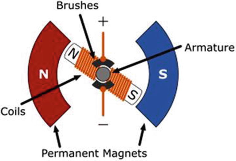
DC motor operation
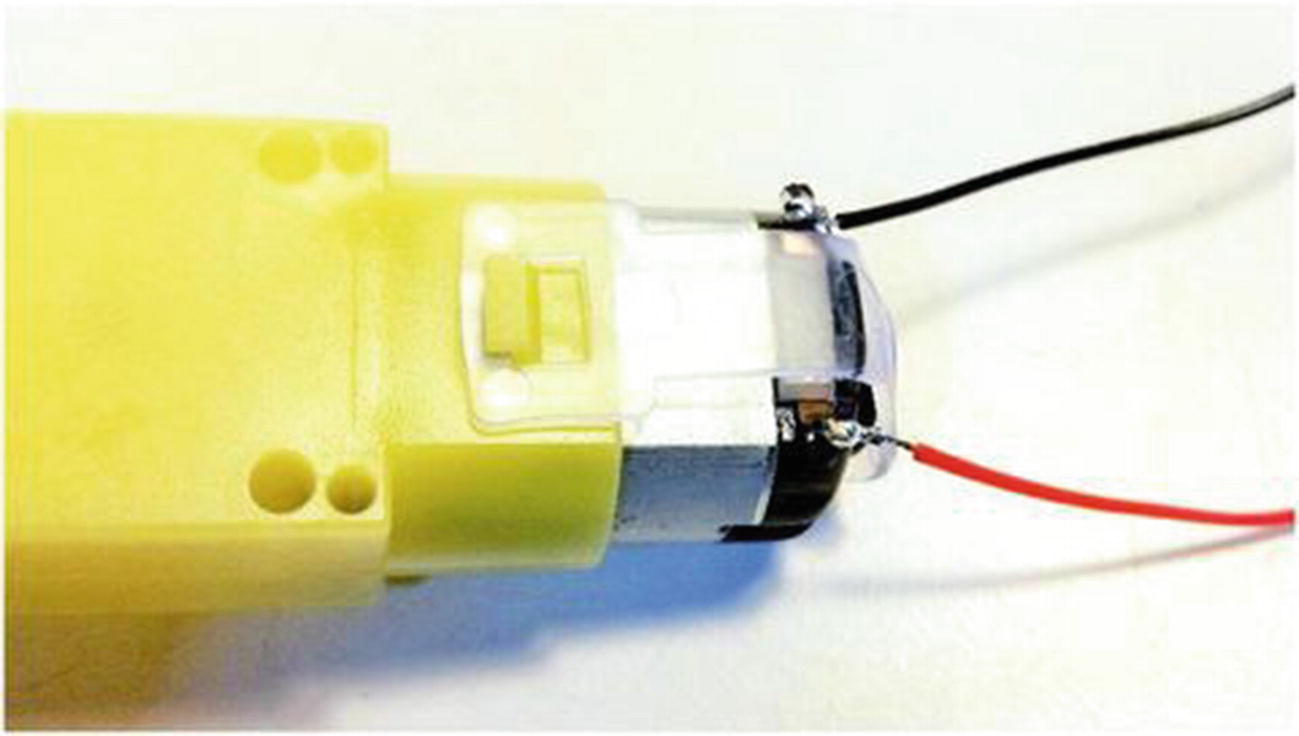
You usually find these motors attached to gearboxes, belts, or chains that serve to amplify the torque of the motor at the cost of rotational speed. This is done because a bare DC motor can produce a lot of speed, but raw speed is rarely useful.
The motors that we are using are of this type. They are simple DC motors attached to gearboxes.
Brushless Motors

Brushless motor operation
In the hobby world, brushless motors are most commonly associated with multirotor aircraft. They are also used extensively in other areas where high speed and efficiency are required, such as in CNC (computer numerically controlled) spindles. You are probably familiar with Dremel tools or routers; both of these devices are types of spindles and use brushless motors.
Stepper Motors
All the motors that I discussed so far have one or more coils working off a single electrical charge. That charge can be positive or negative, changing the direction of the motor.

Stepper motor operation
Servos
A servo is a motor that moves to a specific angle and holds that position. They generally have a maximum rotation of 45–90 degrees in either direction. They do this by connecting a potentiometer to the final output gear. The potentiometer provides feedback to the internal control board. When the servo receives a signal, usually in the form of PWM, the motor rotates until the potentiometer and the signal balance .
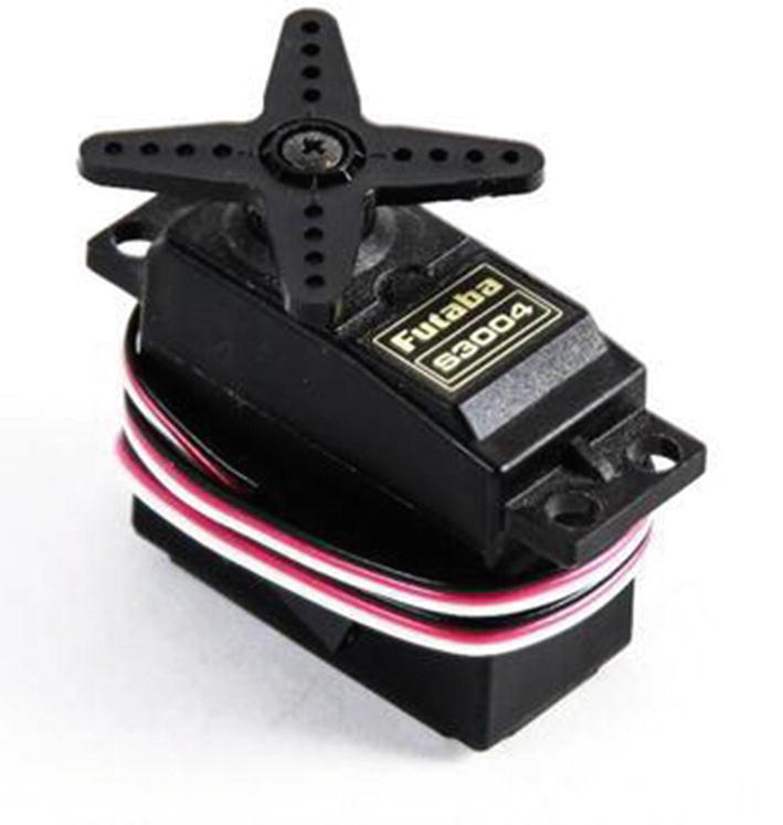
Common servomotor
Servos with the limiters and potentiometers removed are called continuous rotation servos. They are used in applications where torque is required. Many robots are driven by continuous rotation servos.
This is an example where one hobby greatly benefited another. The common hobby servo was originally used for hobby RC aircraft. Since most hobbyists could not afford expensive devices to control their crafts, they figured out how to bring the price down significantly. This, of course, helps us hobby roboticists .
Motor Properties
There are a few things to keep in mind about motors in our projects. The most important is the motor’s electrical properties—specifically, voltage and current.
Voltage
You’re already somewhat familiar with voltage, which is a measure of the electricity needed to operate a device. The Pi is powered by 5 volts but runs on 3.3 volts. The Arduino runs on 5 volts, supplied by the USB port of the Pi. The motors we are using run on 6 volts. It is important to keep these voltages straight. If you were to put 5 volts on a device that runs on 3.3 volts, you could damage your device.
There are devices specifically designed to help manage the voltages in your project. Voltage regulators (step-up or step-down) maintain a constant voltage. The common 7805 5 V regulator takes 6–12 volts and converts it to 5 volts. The excess energy is dissipated as heat, and they can get quite hot.
Voltage regulators are great for voltage supplies, but are of little use for translating 5 volts and 3.3 volts in devices. For this, we use a logic-level converter, which requires a reference voltage from both devices, but safely translates the voltage between devices.
So now you are aware of the differences in the voltage needs of your devices. Next, we look at amperage.
Amperage
Amperage is a measure of current, or the electrical pressure that our devices require to operate. The most common analogy is water through a pipe, where voltage is the size of the pipe and amperage is the amount of water flowing through it. I actually like to change the analogy to use rubber tubing. If you try to push too much water through a rubber tube, bad things happen.
In the electronics world, this is frequently measured in the smaller unit of milliamps, usually noted as mA. For instance, the USB port of most devices is limited to 800 mA of power. This happens to be the same amount of power used by the motors we selected; however, it does not take power spikes into account.
Voltage on a device is somewhat passive. The device uses the voltage that you provide it, never trying to draw more. Amperage is quite the opposite. A device is hungry for amperage and continues to draw what it needs until it is satisfied to do its work or exceeds the available supply.
Components and devices have a certain amount of power that they need to work. They also have a maximum amount of power that they can withstand. Since extra electrical power is converted to heat, if you exceed the maximum tolerable amperage of a device, it gets hot and dies—sometimes spectacularly.
The moral of the story is to “always pay attention to the current you are drawing.” And this does not only apply to motors. LEDs are notorious for drawing a lot of current .
Motors and Amps
Motors are notoriously power-hungry devices. They are constantly trying to fulfil their purpose: to spin. When there is no load, weight, or resistance on a motor, it spins happily at its minimum current draw. Start to add resistance, however, and the motor draws more and more current until it reaches the maximum it can draw, which is called the stall current. The stall current is essentially the amperage of a motor when the shaft is physically restrained from moving.
When a motor starts, rapidly changes direction, or encounters too much resistance to spin, the power that it consumes increases drastically. If this sudden draw is too much for the supply, something is damaged. Let’s take an 800 mA source, such as a USB jack; if the motor suddenly draws 1 amp or greater, the USB jack will probably be damaged .
Motor Drivers
Most microcontrollers, microprocessors, and electronics can only handle a small amount of current. If one pulls too much current, it starts to burn out. Because motors usually easily exceed this maximum current, you generally don’t want to connect a motor of any significant size directly to your processor. So we will use a device called a motor driver or a motor controller.
A motor controller is designed for this specific purpose. It uses the low power signal from your microcontroller to control a much larger current and/or voltage. In our case, we are using a motor controller to control 6 volts with 3.3 volts from the GPIO pins. We are doing this through a series of components that have a much larger 1.2 A (1,200 mA) current tolerance and can handle brief spikes up to 3.0 A (3,000 mA) .
Working with Motor Controllers
Let’s look at two motor controllers. The first is the DC & Stepper Motor HAT by Adafruit. This controller board is designed specifically to mount onto the Raspberry Pi. The combination of utility and convenience makes it my preferred choice for projects like ours.
The other motor controller is the L298N, which is an H-bridge IC. Although the L298N is actually a discreet component—a chip—there are many manufacturers that have built it onto a convenient breakout board. This type of board is typically being referred to when someone mentions an L298N motor controller. The one used in this book is a generic version that I found on Amazon for $5. Some of my friends said that I paid too much for it.
Adafruit DC & Stepper Motor HAT
The motor driver in this project is one from Adafruit available at www.adafruit.com/products/2348. Information on how to use it is at https://learn.adafruit.com/adafruit-dc-and-stepper-motor-hat-for-raspberry-pi. In fact, much of what we’ll be going over came from this Adafruit website.
It can control up to four DC motors or two stepper motors.
Communication is handled via the I2C serial channel, which allows multiple devices to be stacked (this is why we used the longer pins on the header).
Because it is using I2C, it has its own dedicated PWM module for controlling the motors, so we don’t have to rely on the PWM on the Pi proper.
It has four H-bridge motor control circuits with 1.2 A current, 3.0 A peak current, thermal shutdown, and internal protection diodes to protect your board.
There are four bidirectional motor controls with 8-bit speed control (0–255).
There is an easy connection with the use of terminal blocks.
There are ready-made Python libraries.
Some Assembly Required
The board comes in a kit and requires soldering. If you haven’t already done so, you need to assemble it before proceeding with the project. Remember, we specified longer pins for the header, so don’t use the one that came with the kit.
It’s time for soldering practice.
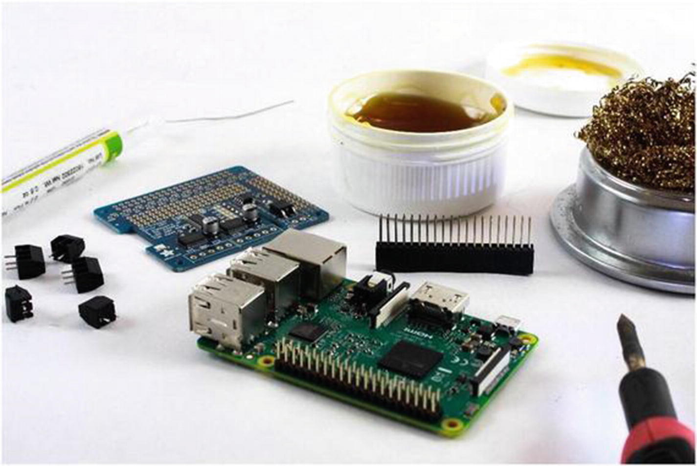
Preparing to assemble the Motor HAT
Assembling the Motor HAT is very easy, although there is soldering involved. You can find detailed instructions for assembly on the Adafruit website at https://learn.adafruit.com/adafruit-dc-and-stepper-motor-hat-for-raspberry-pi/assembly.
- 1.
Mount the extended header onto the Raspberry Pi’s 40-pin header (see Figure 6-6). This helps stabilize things as you solder.

Extended stacking header on the Pi’s 40-pin GPIO
- 2.
Mount the Motor HAT circuit board onto the headers (see Figure 6-7). To help hold the board at a better angle for soldering, you may want to put something to support the other side. One of the terminal blocks works well for this.
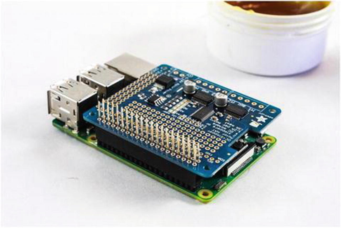
Circuit board mounted on the header
- 3.
Solder the first pin.
- 4.
Once the first pin is soldered, heat it up again and adjust the board so that it sits properly (see Figure 6-8). When the solder for the pin cools, it will hold the board at the right angle while you solder the rest of the pins. If you supported the board with a terminal block or something else so that the board is sitting straight, you may be able to skip this step.
Adjusting the placement and angle of the board
- 5.
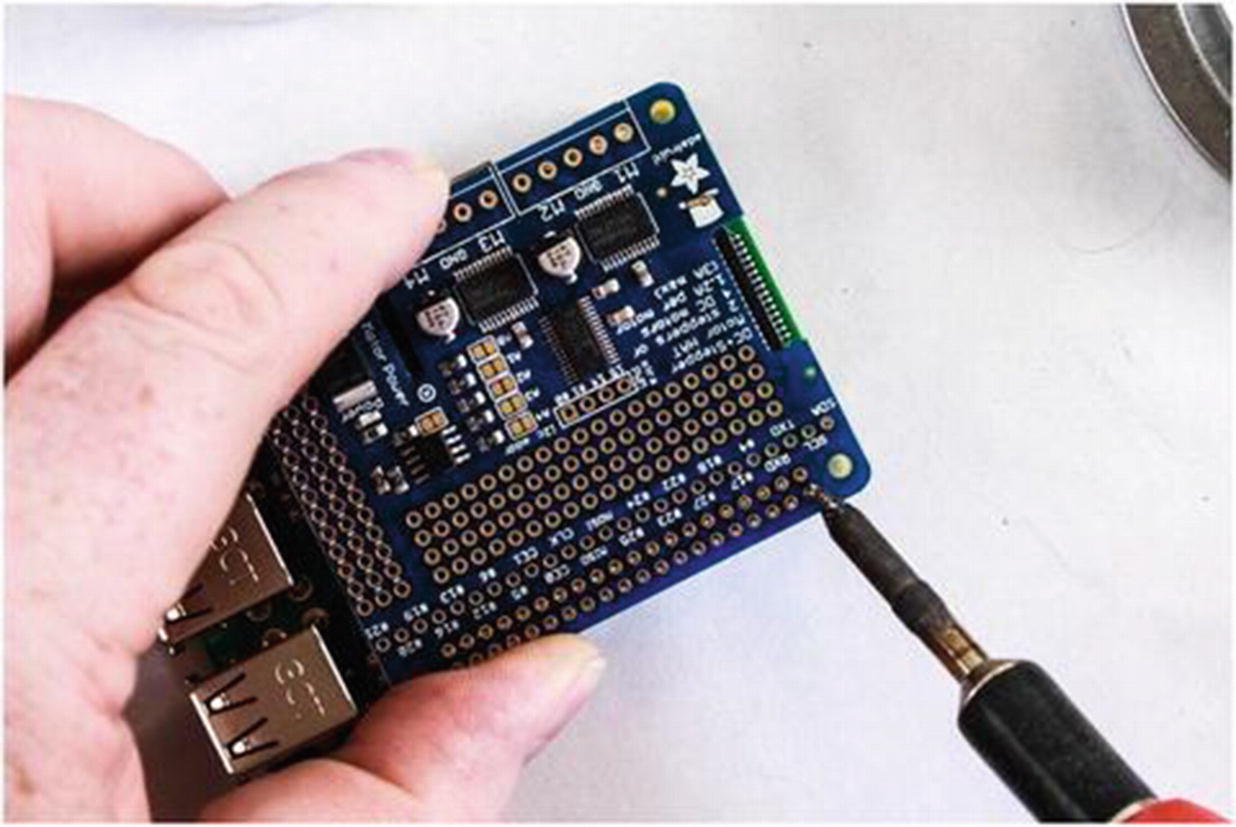
Solder the rest of the first row (see Figure 6-9). You want a nice, clean, shiny joint.
Solder the first row of pins
- 6.
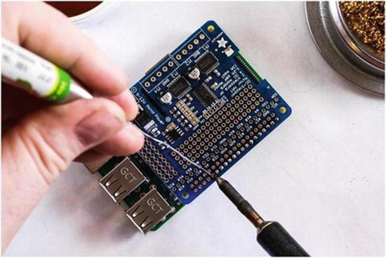
Rotate the board 180 degrees and solder the second row (see Figure 6-10).

Rotate the Pi and solder the remaining pins
- 7.
Remove the HAT from the Pi.
- 8.
Mount the screw terminals onto the board (see Figure 6-11).

Adding the terminal blocks to the circuit board
- 9.
Use tape to hold the terminals in place while you flip the board over (see Figure 6-12).
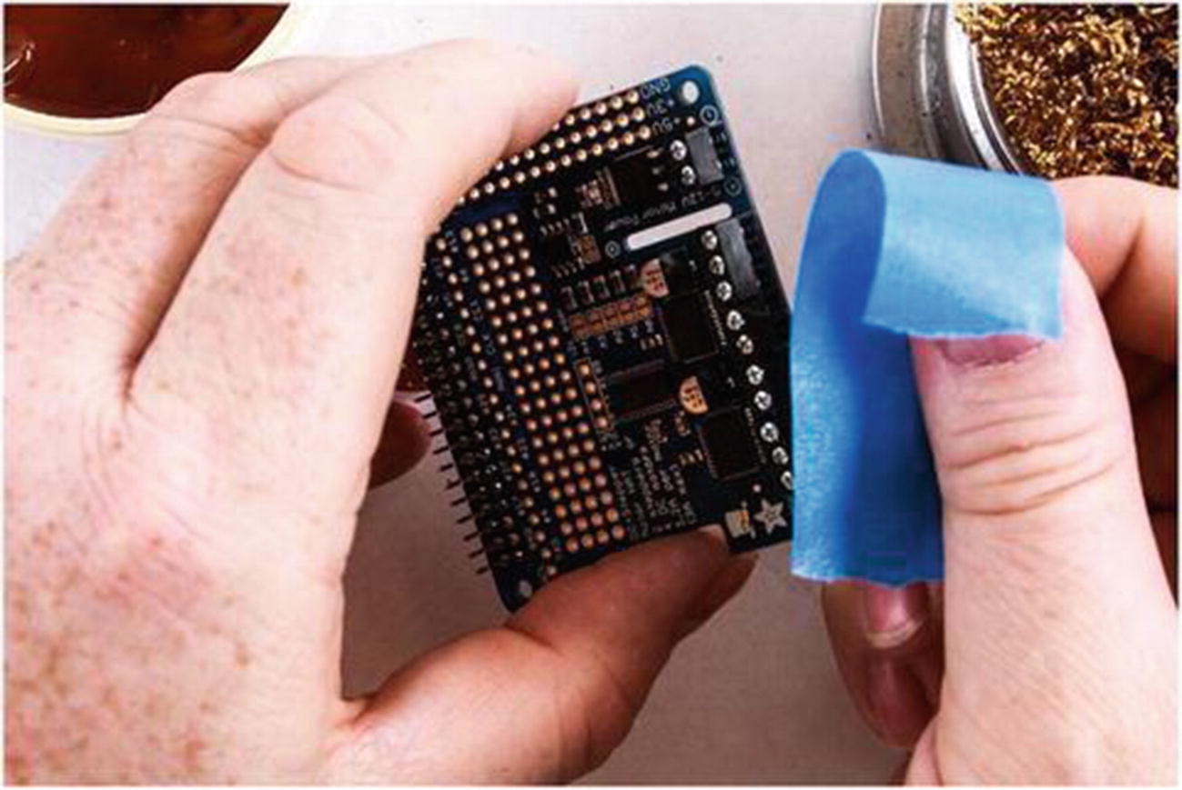
Tape helps hold the terminal blocks on the board while you turn it over to solder them into place
- 10.
Solder the terminals in place (see Figure 6-13).

Soldering the terminal pins

The completed board mounted on the Raspberry Pi. The orange support piece is 3D printed
Hooking Up the Motor Controller
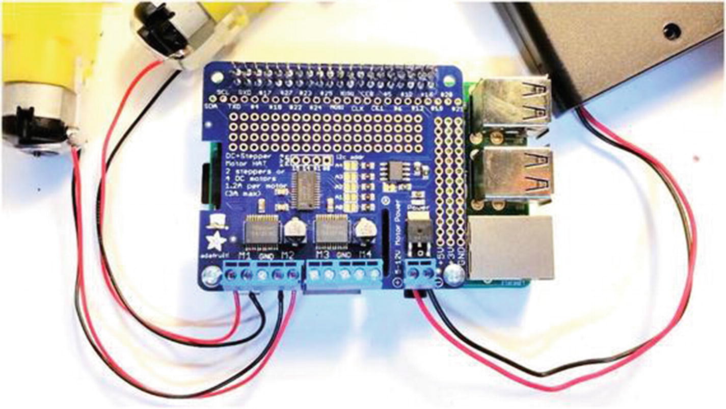
Connecting the Motor HAT is pretty straightforward. Simply mount the board on the GPIO header of the Pi. There are a couple of things to note, however. First, be careful not to bend any of the pins on either the Raspberry Pi or the HAT. It is remarkably easy to do. The header pins on the Motor HAT are particularly susceptible to bending.

Adafruit Motor HAT mounted on a Raspberry Pi
Once the board is mounted and safely insulated from shorting, it’s time to connect the motors. For the first tutorial, we’re only going to use one motor. The second piece of code controls two, so we might as well get them connected now.
Leads soldered to motor terminals

Tinned lead
- 1.
Make sure that the terminal blocks are open with the screw inside the block all the way to the top. Be sure not to remove the screw. You’ll need to use a pretty fine Phillips head screwdriver.
- 2.
Insert one of the tinned leads into the hole on the side of the terminal block marked M1 (see Figure 6-18). It doesn’t matter which wire goes to which port, as long as both wires go to different ports for the same driver (in this case, M1).
- 3.
Tighten the screw corresponding to the hole you inserted the wire into.
- 4.
Repeat the procedure for the second lead from the motor.

Motor connected to the Motor HAT
At this point, if you are so inclined, you can connect the second motor as well. I tend to reverse the order of the leads since they are destined for opposite sides of the robot. You want a forward command to turn the left motor in one direction and the right motor in the other direction. If they both turn in the same direction electrically, then the robot just spins in place.

External battery pack connected to the Motor HAT
Completed connections to the Motor HAT
Using the Motor HAT
With the Motor HAT mounted and your motors and motor power supply connected, it’s time to boot up the Pi and log on.
The Adafruit Motor HAT uses a protocol called I2C to communicate with your Raspberry Pi. I2C is a serial protocol designed to use a minimum number of pins for sending and receiving data. Generally the protocol uses a total of four pins to connect with other devices: SCL, SDA, VCC, and GND. The particulars of I2C are beyond the scope of this book, but if you want to learn more about it, check out https://learn.adafruit.com/circuitpython-on-raspberrypi-linux/i2c-sensors-and-devices.
There are a couple of steps to get the Motor HAT working on your Pi. First, we will need to enable I2C. This and most other communications protocols are disabled by default on the Pi. Once this is done, we will install the necessary library.
Enabling I2C
- 1.
In the upper-left corner of the Raspberry Pi OS screen, click the raspberry logo.
- 2.
Click Preferences and then Raspberry Pi Configuration. This will open the Raspberry Pi Configuration panel.
- 3.
Select the Interfaces tab.
- 4.
Click Enable for I2C.
- 5.
Click OK.
Installing the Library
- 1.
Open a terminal window.
- 2.
Type sudo pip3 install adafruit-circuitpython-motorkit and press Enter.
At this point, your Pi is updated with the necessary libraries, and it’s time to get started with the code.
The Code
We will start with simply turning a single motor. The speed of the motor is denoted as a decimal value between 0 and 1. Zero is a dead stop, one is full speed, and half speed would be 0.5.
Turning multiple motors is a simple expansion of this, as you will see in the second sample.
Turning a Single Motor
- 1.
In the Thonny IDE, create a new file and save it as motors.py.
- 2.Enter the following code:import timefrom adafruit_motorkit import MotorKit# create motor objectkit = MotorKit()# run motor forward 1 secondkit.motor1.throttle = 1.0time.sleep(1.0)# stop motorkit.motor1.throttle = 0.0time.sleep(0.25)# run motor reverse 1 secondkit.motor1.throttle = -1.0time.sleep(1.0)# stop motorkit.motor1.throttle = 0.0
- 3.
Save the file.
- 4.
Press F5 to run the program.
Let’s go through the code.
To stop the program, press Ctrl-C on the keyboard.
Note that the program ended, but the motor continues to turn. That’s because the Motor HAT is freely running. This means that the controller continues with the last command received from the Pi. If we don’t tell it to stop, it won’t.
Now we are going to do something interesting, something we haven’t done before. We’ll wrap the motor drive code into a try/except block. It is a piece of code that allows us to capture any errors that occur and then gracefully handle them.
- 1.Change the code for the while loop to read as follows:try:while True:# run motor forward 1 secondkit.motor1.throttle = 1.0time.sleep(1.0)# stop motorkit.motor1.throttle = 0.0time.sleep(0.25)# run motor reverse 1 secondkit.motor1.throttle = -1.0time.sleep(1.0)# stop motorkit.motor1.throttle = 0.0time.sleep(0.25)except KeyboardInterrupt:kit.motor1.throttle = 0.0
- 2.
Run the program.
- 3.
Let it run for a moment, and then press Ctrl-C.
The motor will now stop when the program exits.
Python captures the KeyboardInterrupt event and executes that last line of code before exiting. The code releases the motor and simply turns it off.
Turning Two Motors
Turning a single motor is great and dandy, but our robot is going to have two motors, and we want them to operate independently. We also want them to be able to change speed and direction.
- 1.
Create a new Python file from Thonny.
- 2.
Save the file as two_motors.py.
- 3.Enter the following code:import timefrom adafruit_motorkit import MotorKit# create motor objectkit = MotorKit()try:while True:# ramp up speed from 1 to 255for i in range(100):j = 100-i# run motors forward 1 secondkit.motor1.throttle = i/100kit.motor2.throttle = j/100# stop motorkit.motor1.throttle = 0.0kit.motor2.throttle = 0.0time.sleep(0.25)for i in reversed(range(100)):j = 100-i# run motors reverse 1 secondkit.motor1.throttle = i/100kit.motor2.throttle = j/100# stop motorkit.motor1.throttle = 0.0kit.motor2.throttle = 0.0time.sleep(0.25)except KeyboardInterrupt:kit.motor1.throttle = 0.0kit.motor2.throttle = 0.0
- 4.
Save the file.
- 5.
Press F5 to run the program.
For the most part, the code is the same. We added a few for loops to count up to 100 and back down again. We created two variables to hold this value; the second one inverts the value by subtracting it from 100. Since the throttle is a decimal value between 0 and 1, we divide the speed variable by 100. Once both motors have sped up and down again, we change direction and do it again. We use the same exit code as we did before.
L298N Generic Motor Driver
The L298N is a common H-bridge motor controller chip. Several manufacturers have mounted the chip on a board and added all the necessary support electronics. The end result is a popular, generic motor controller.
H-Bridge Motor Controller
The H-bridge motor controller is the most common motor controller that you will encounter. It gets its name from the distinctive H shape seen in the schematic. An H-bridge essentially consists of four gates that control current flow through the motor. Depending on how the gates are opened and closed, you can control the direction in which the motor spins.
On the L298N, there are two enable pins (one for each motor) and four input pins. The in1 and in2 pins control motor 1, while in3 and in4 control motor 2. Figure 6-21 shows how the gates are arranged; in1 controls S1 and S4, and in2 controls S3 and S2. When in1 or in2 is high, their respective gates are closed. When they are low, the gates are open.
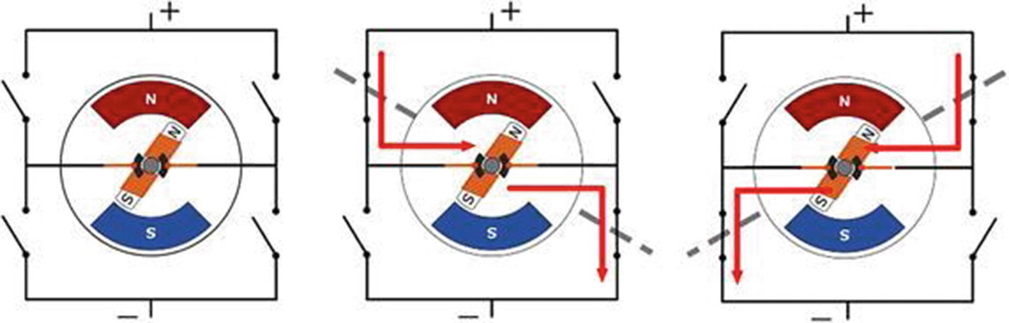
H-bridge motor controller operation
That leaves the enable pins, enA and enB, which are used for setting the speeds of the motors. This is why we use PWM on these pins. PWM allows us to vary the speed of each motor. If we used a standard digital pin, we could start and stop the motor, but it would be either full power or no power. PWM allows us to have more control over our motors.
Using the L298N
There are a few ways to use the L298N; each has its benefits and faults. One method is to connect the pins to the Raspberry Pi, which has the virtue of being directly controlled by the Pi. The drawbacks are that you may have to use a logic-level converter since the Pi’s pins are 3.3 volts and the controller is 5 volts. Also, you lose the ability to control the speed. Speed control requires PWM, and as I discussed in earlier chapters, that is one area where the Pi is wanting.
My preferred method for connecting to the L298N is through the Arduino. In this way, you have speed control through PWM. Also, since the Arduino and the controller are both 5 volts, there is no need to use a logic-level converter. Of course, the drawback here is that you have to pass the motor instructions via Serial to the Arduino.
Arduino Code
- 1.
Open a new sketch in the Arduino IDE.
- 2.
Save the sketch as L298N_passthrough.
- 3.Enter the following code:int enA = 9;int in1 = 8;int in2 = 7;int in3 = 5;int in4 = 4;int enB = 3;int enAVal, in1Val, in2Val, in3Val, in4Val, enBVal;void setup() {// put your setup code here, to run once:Serial.begin(9600);pinMode(enA, OUTPUT);pinMode(in1, OUTPUT);pinMode(in2, OUTPUT);pinMode(in3, OUTPUT);pinMode(in4, OUTPUT);pinMode(enB, OUTPUT);}void loop() {// Only work if there is data in the serial bufferwhile(Serial.available() > 0){// Read the ints from the serial portenAVal = Serial.parseInt();in1Val = Serial.parseInt();in2Val = Serial.parseInt();// Only read the next three if there is dataif(Serial.available() > 0){in3Val = Serial.parseInt();in4Val = Serial.parseInt();enBVal = Serial.parseInt();}// Write the values to the L298NanalogWrite(enA, enAVal);digitalWrite(in1, in1Val);digitalWrite(in2, in2Val);digitalWrite(in3, in3Val);digitalWrite(in4, in4Val);analogWrite(enB, enBVal);// Purge any remaining data because we don't need itwhile(Serial.available() > 0){char x = Serial.read();}}}
- 4.
Save the sketch and upload it to the Arduino.
You won’t see anything happening on the Arduino. What we’ve done is load the Arduino with code that simply reads the serial port and passes the values read to the L298N.
At the end of the sketch, we added a small while loop. If we have anything left in the serial buffer after reading all six values, we need to clear it out so that there is no straggling data in the buffer for the next cycle. This block simply reads all the remaining bytes and removes them from the buffer.
Hooking Up the L298N
Hooking up the motor controller is a little more complicated than just plugging it into the header. We’ll connect through the Arduino to take advantage of the PWM pins. As with the Motor HAT, we’ll provide the motor controller with external power from the four–AA battery pack. This provides the 6 volts that the motors want, without frying the Arduino.
Turning One Motor
- 1.
Connect enA on the motor controller to pin 9 on the Arduino. You may need to remove a jumper.
- 2.
Connect in1 to pin 8.
- 3.
Connect in2 to pin 7.
- 4.
Connect a ground pin on the Arduino to the ground post on the screw terminal. This is likely the middle post.
- 5.
Connect a motor to the motor controller by connecting one lead to out1 and the other to out2.
- 6.
Connect the black lead from the battery pack to the ground terminal on the L298N.
- 7.Connect the red lead from the battery pack to the positive terminal. It is usually labeled + or VCC.
 Figure 6-22
L298N single-motor wiring
- 8.
Open a new file in Thonny.
- 9.
Save the file as L298N_1_motor_example.py.
- 10.Enter the following code:import serialimport timedirection = 1ser = serial.Serial("/dev/ttyACM0",9600,timeout=1)def driveMotor(int speed, int drct):enA = speed# determine directionif drct == 1:in1 = 1in2 = 0else if drct == -1:in1 = 0in2 = 1else:in1 = 0in2 = 0valList = str(enA) + ',' + str(in1) + ',' + str(in2)serString = ','.join(valList)ser.write(serString)time.sleep(0.1)while 1:# ramp up speedwhile motSpeed < 256:driveMotor(motSpeed, direction)motSpeed = motSpeed + 1# ramp down speedwhile motSpeed > 0:driveMotor(motSpeed, direction)motSpeed = motSpeed – 1# reverse directiondirection = -direction
- 11.
Save and run the file
The motor should begin spinning, getting faster until it reaches its top speed. At that time, it slows to a stop, reverses direction, and repeats. This continues until you press Ctrl-C to stop the program.
Turning Two Motors
- 1.
Connect a lead from pin 5 on the Arduino to in3 on the motor controller.
- 2.
Connect a lead from pin 4 to in4.
- 3.
Connect a lead from pin 3 to enB.
- 4.
Connect the leads from the second motor to the out2 terminals. Again, it matters very little in this exercise which lead goes to which terminal. Later, when you are mounting the motors onto the robot, you want to make sure that the motors are connected so that they turn opposite to each other. For now, however, we only care that they actually turn.

L298N two-motor wiring
- 5.
Open a new file in Thonny.
- 6.
Save the file as L298N_2_motor_example.py.
- 7.
Enter the following code:
This code was not much different from the previous exercise. All that we did was add the enable and input variables for the second motor. Both motors should be spinning at the same speed. They speed up, slow down, and then reverse direction. Take a look at the code and determine how to get the motors to spin independently of each other.
Summary
In this chapter, we looked at the common types of motors: DC, coreless, stepper, and servo. We assembled the Adafruit DC & Stepper Motor HAT. (You should now be pretty comfortable with the soldering iron.) Then, you learned how to connect your motors to it and made them spin.
We also looked at a common, generic motor controller. The L298N works a little differently in that the direction is set by altering the state of two pins. We connected the L298N through the Arduino to take advantage of the PWM pins to control the speed of the motors, as well as the direction. We could have just as easily connected the enable pins to digital out pins on the Raspberry Pi GPIO header. However, having discrete control of the motors’ speed is important. In an upcoming chapter, you see why this is important.
At this point, you have all the information that you need to build a simple little robot. You’ve learned about programming in both Python and Arduino. You’ve worked with sensors to allow your robot to detect its surroundings. And finally, you got your motors to spin, so you have motion. Logic, sensing, and movement are the essence of every robot. Everything else is a more advanced version of these elements.
Now that you know everything you need to know about robots, we’re going to assemble the chassis kit and build a robot. After that, we jump into making our robot more capable and smarter. We will start with IR sensors, move on to control algorithms, and then give the robot eyes—well, an eye.