
Chapter 12. Project: Smart Thermostat
You may have heard of so-called “smart” thermostats (I suspect that many people have at least seen the advertisements for them). These devices are a type of programmable digital temperature controller. You might even have one installed in your house or apartment. Some allow you to change settings using Bluetooth or some other wireless connection method, along with an associated app for a smartphone or tablet. Others offer data collection capabilities with wireless download, which can be useful if you want to find out when you are using the most energy to heat or cool your home. There are also, of course, some that don’t do much more than what the old-style bimetallic coil types did, except that an LCD display is used instead of a dial and some switches.
Warning
Disclaimer: If you elect to build and use the thermostat described in this chapter, you do so at your own risk. While it utilizes low-voltage circuits with minimal shock hazard, there is still the risk of damage to your heating or cooling equipment from excessive power cycling or temperature settings that exceed the safe limits of the equipment (most systems have built-in safeguards, however). Use only the low-voltage control circuit for your heating and cooling equipment. DO NOT CONNECT YOUR CUSTOM THERMOSTAT TO HIGH-VOLTAGE (110V AC or greater) CIRCUITS. This includes evaporative coolers and electric heaters.
Background
There are multiple ways to improve on a classic bimetallic coil thermostat like the one shown in Figure 12-1. This type of device has been around for about a century. It uses a coil comprised of two different metals, each with a different thermal expansion coefficient, so that as the temperature changes the coil tightens or loosens slightly. This movement is then used to bring some contacts together to open or close a circuit, or in some versions a small sealed glass tube containing two contacts and a drop of mercury is moved so that the mercury bridges the gap between the contacts and completes the circuit (the KY-017 tilt sensor module described in Chapter 9 uses this same technique). The control action is either on or off; there is nothing in between.
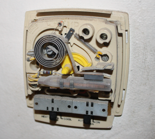
Figure 12-1. Electromechanical thermostat
In this chapter we’ll look at what is involved in designing, building, and programming a smart thermostat using only readily available Arduino boards and common add-on components. But before we dive into that, we need to get a basic understanding of what, exactly, it is that we want to measure and control.
HVAC Overview
The main idea behind altering the temperature in a structure is to either put heat in or take heat out. Or, to put it another way, cold is just the absence of heat, and we can alter the amount of heat in a system to achieve a particular temperature. Adding heat to an environment can be accomplished with a furnace of some sort (natural gas, propane, oil, wood, or coal), electric heating elements, or solar energy. In a heat pump system the heat in the outside air is extracted and put back into the structure, which is similar to running an A/C unit in reverse. To remove heat from a structure, it is extracted using a refrigeration system that employs the condensation and evaporation cycle of a refrigerant fluid (ammonia, Freon, or any one of a number of modern coolants). The inside heat is absorbed by the refrigerant fluid, which then transfers it to the outside in a closed-cycle system. Some large-scale cooling systems use chilled water to achieve the same result, but the physical plant (the equipment and the building to house it) tends to be large and expensive to operate, so these types of systems are usually found only in university buildings, high-rise office structures, hospitals, and other large facilities. Chilled water systems aren’t commonly used in residential settings outside of large apartment buildings.
In many residential settings the heating and cooling are handled by two separate systems, but in other cases the heater and air conditioner may all be in the same large cabinet situated on the roof or along the side of the house. A heat pump does both heating and cooling, depending on how it is configured at any given time, and often consists of two units, one inside the house and one outside. In any case, in a conventional thermostat there will usually be a switch to select automatic or manual fan operation, and another to select the mode (heating, cooling, or off). A dial or lever sets the target temperature, or setpoint. The entire system, which incudes the heating unit, the cooling unit, and the thermostat, can be referred to as the heating, ventilation, and air conditioning, or HVAC, system. (Actually, the term HVAC is most often heard when referring to large commercial systems, but I will use it here because it’s more convenient than writing “heating and air conditioning system.”) With the possible exception of an active air-exchange ventilation function, a residential HVAC system does everything the large system can do, just at a smaller scale.
An important thing to note is that most HVAC systems can and do operate as closed-loop circulation systems. In other words, they work by continuously recirculating the air in the structure. While some systems might have the ability to draw in outside air or exchange inside and outside air (the V in HVAC), some don’t, and as a result the smell of last night’s burned dinner will tend to linger for a while before it finally dissipates. This is also why many homes have a distinct smell unique to that residence. As a child I noticed that the inside of a neighbor’s house always smelled like fried chicken in the summer when they ran their A/C, so I assumed that they really liked fried chicken. I never did learn the actual source of that peculiar smell.
Temperature Control Basics
Temperature control involves controlling the subsystems that will either heat or cool an environment to achieve a specific temperature (setpoint). In most cases this is an all-on or all-off type of operation; there are no intermediate heating or cooling rates in most residential HVAC systems. I say “most” because it’s possible that someone, somewhere, has a variable-output resistive heater system, but I’ve yet to see anything like that outside of a laboratory or industrial setting.
The “all-or-nothing” nature of an HVAC system means that the actual indoor temperature will never be exactly at the setpoint, except for brief periods as it either falls or rises. For example, let’s assume that we’re running the air conditioner, with a target setpoint of 72 °F (22 °C). If we were to record and plot both the inside and outside temperatures over the course of a day we might get something like Figure 12-2 (this is not real data, of course, it’s just for illustration purposes).
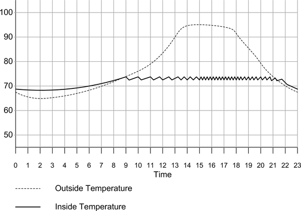
Figure 12-2. Temperature plot over the course of a day
In Figure 12-2 we can see where the air conditioner is active because the interior temperature drops. Early in the day it doesn’t cycle (turn on and turn off) as often as happens later in the day. It takes time for the heat outside to work its way through the structure, and the better the insulation is, the longer it takes for the inside to start to warm up. Later in the afternoon, the air conditioner is working hard to keep the inside at the setpoint temperature. Things don’t start to slow down until later in the evening as the outside temperature drops.
A controller with only two states, on or off, is called a hysteresis controller. It is also known as a bang-bang controller. The amount of hysteresis in the controller determines how often the cooling or heating equipment will turn on and for how long. You can think of hysteresis as the lag between when a system turns on, or turns off, based on a setpoint value somewhere in between. A physical example of this is the snap-action of a three-ring binder. It takes some effort to open the rings, and again to close them, but once in the open or closed state the rings will stay that way.
Figure 12-2 is estimated, but it is representative of the effect of a conventional thermostat on the temperature in a typical residential structure. When the inside temperature reaches about 73 °F the air conditioner is powered on, and it continues to run until the temperature drops to just below 71 °F. That means there is about 2 degrees of hysteresis in this hypothetical system. This range is referred to as the “hysteresis band” (actually, the hysteresis band in this system is too tight, and the A/C is cycling far too often later in the day).
Each on/off action of the HVAC system is referred to as a cycle. Figure 12-3 shows what happens when the difference between the on and off points becomes smaller (less range between Hmax and Hmin, which define the hysteresis band). The system is able to maintain the setpoint temperature better with a tighter hysteresis, but at the expense of cycling the power much more often. We would ideally want to make the hysteresis band as wide as possible, because each time the heater or A/C unit cycles brings it one step closer to wearing out and failing. It also drives up the electric bill.
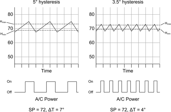
Figure 12-3. Effect of hysteresis
While the 5° hysteresis band is more energy-efficient and doesn’t beat up the equipment with as much cycling as the 3.5° band, it also means that the actual temperature can swing as much as 7° between hot and cool. (Remember that these graphs are illustrative, and do not reflect real data.)
There are multiple factors that affect how often a heating or cooling system will cycle, the most obvious being how quickly heat is being removed when running the A/C, or how quickly heat is being introduced when running the heater. Less obvious, but also important, are things like humidity and interior air flow. As the humidty increases air will retain more heat, which can help when heating. An A/C unit also acts as a dehumidifier, condensing and removing moisture from the air passing over the cold evaporator coils in the system, and dry air evaporates sweat more readily, which allows us to cool off faster. Stagnant air (that is, air that’s not moving unless the HVAC system is active) can lead to “hot spots” or “cold spots” in a structure, and it’s possible that the thermostat will end up regulating just one part of an interior space if the rest of the air isn’t passing by it.
Ideally a temperature control system should be able to sense the temperature in all parts of a structure, but in the real world this often isn’t the case. There will invariably be a room that gets direct sunlight most of the day, while other areas are shaded, or perhaps a room that has poor air flow. So even though the thermostat is doing its job and working to keep the temperature in the immediate area where it is located at the desired setpoint, other parts of the structure will not be heated or cooled correctly. Just moving the air around can help avoid this, and monitoring the humidity will also help to determine when to run the fan or when to use the heating or cooling. Running the fan alone is a lot less expensive than running the heater or A/C unit.
Smart Temperature Control
The main idea behind a smart thermostat is to reduce the amount of energy wasted and achieve a more even temperature distribution within the structure. This might involve altering the cycle time (i.e., adjusting the hysteresis), only running the system when someone is in the house, altering the setpoint based on the time of day and/or day of the week, and taking advantage of the built-in fan in the HVAC system.
Some common features of modern commercial digital thermostats include adjustable cycle times, automatic heating/cooling mode changeover, and day-by-day programmability. We’ll briefly review these capabilities to see which ones make sense for a small project like the one described here.
Adjustable cycle times can be used to reduce frequent on/off heating or cooling cycling. This can occur when the temperature is at or near the setpoint and varies just enough to cause the heater or air conditioning (A/C) to turn on. What it does, in effect, is increase the hysteresis in the system, so that it takes longer to cycle when the temperature is hovering around the setpoint, but the amount of hysteresis is reduced when the temperature rapidly changes one way or the other over a short period of time.
Auto-changeover allows the system to switch between cooling and heating as necessary. If, for example, you are experiencing warm days and cold nights, then the thermostat will automatically switch from cooling to heating at night to maintain a relatively constant average indoor temperature. The Arduino thermostat will support auto-changeover and adjustable cycle times as well.
Profile scheduling is a big feature with smart thermostats. Most programmable digital thermostats have the ability to schedule heating or cooling for specific days of the week, so if your house is empty during weekdays you can trim some expense from your electric bill by not running the heater or A/C when there is no one home to appreciate it. By the same token, some models allow you to automatically “dial down” the heating or cooling at night, while the home’s occupants are asleep. Our controller will have the ability to create profiles (also sometimes called programs) for day, night, and weekend operation.
A digital thermostat can be packaged in a slick-looking enclosure with a high-tech glowing faceplate and a numeric display behind frosted plastic, but that’s just marketing razzle-dazzle. It can also be housed in a commonly available plastic enclosure. It may not look as flashy and high-tech as the commercial units, but that has no bearing on how well it works, or how easily someone can use it. You can save money and time by using a low-budget enclosure for this project, and what I decided to use is definitely low-budget.
Project Objectives
The primary objective of this project is to create a replacement for a conventional residential thermostat. There are numerous descriptions for Arduino-based thermostat projects available online, and this project is similar to many of them. There are only so many ways to arrange an Arduino, a temperature sensor, a simple display, and a relay or two. What makes this project unique is the incorporation of a humidity sensor and the ability to use the fan alone to move air around and help shift cool or warm air to where it’s needed without lighting up the heater or powering up the A/C unit.
Our Arduino thermostat will also have the ability to use the interior temperature and humidity data to determine if it needs to adjust the cycle time. There is also the option to add an additional sensor to read the outside temperature and humidity. Finally, it will use relays to connect to existing 24VAC control wiring used by most residential HVAC systems in the US, so there’s no serious shock hazard and no real risk to your heating or cooling equipment (at least not electrically—it is still possible to cycle too fast and damage the compressor or heater ignition components).
This project is very straightforward, and requires a minimal amount of parts and very little soldering. Actually, the two main challenges are coming up with a good enclosure and programming the device.
The thermostat will be designed to replace a conventional low-voltage four-wire residential thermostat. It is not limited to four-wire systems, however. Controlling just a heater or an A/C unit alone is simply a matter of not using all the available control outputs and making some minor modifications to the software.
Definition and Planning
Based on what we’ve covered so far we can identify the basic features we want to incorporate into our design. These involve the functions already provided by a conventional four-wire thermostat, plus some additional capabilities based on humidity:
-
Real-time clock
-
Inside humidity sensor
-
Inside temperature sensor
-
Automatic heating or cooling operation
-
Automatic fan control
-
Seven-day scheduling
The basic version of the HVAC controller is similar in many ways to the units available at big-box home improvement stores (and even some of the small-box local hardware stores), from HVAC supply houses, and from various vendors online.
Note
This project intentionally avoids dealing directly with the high-voltage AC control circuits in an HVAC system. It is intended for low-voltage (24VAC) systems only. High-voltage AC can damage your HVAC equipment, burn down your house, and kill you (not necessarily in that order). If you need that type of system, consider a commercial controller with a UL and CSA safety rating, and hire a licensed electrician or HVAC technician to install it.
The controller will use an Arduino Nano mounted on a screw terminal prototype shield. A real-time clock (RTC) module will be used to keep track of the date and time. The Arduino PCB stack mounts to the lid of the enclosure. A quad relay module with be mounted inside the enclosure on the bottom panel. All the wiring will enter the enclosure through a hole in the bottom.
Design
The Arduino thermostat is intended to be a drop-in replacement for a standard four-wire thermostat. It is not intended for systems with multistage heating or cooling, or a heat pump system. It is best suited for older homes with a conventional thermostat, like the one shown in Figure 12-1.
Functionality
The Arduino thermostat has three basic functions: heat, cool, and fan. Figure 12-4 shows a block diagram with the primary components. The secret to success lies in how those basic functions are used to achieve the most efficient operation.
A rotary encoder will be used for various functions such as setting temperatures, stepping through days of the week, and so on. The LCD shield also has a set of pushbuttons, but these will not be used.
Many older HVAC systems have only four wires, while some newer systems also have auxiliary power wiring. The Arduino thermostat can use this AC source if it is available if a small power supply is also mounted in the enclosure. For this version of the thermostat I will use an external wall power supply, or wall-wart. Ideally it would be better to draw power from the HVAC wiring, but many older systems don’t have a spare 24VAC line available.
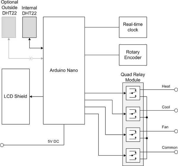
Figure 12-4. Arduino thermostat block diagram
Figure 12-5 shows how a typical older thermostat might be wired internally. The actual internal details will, of course, vary from one type to another, but the basic idea is the same.
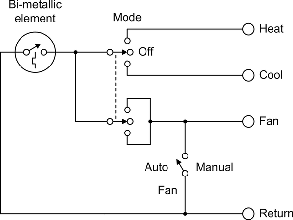
Figure 12-5. Typical old-style thermostat internal circuit
A key thing to note about this type of old-style thermostat is that the fan is wired so that it will always come on when either heating or cooling is enabled. It is not a good idea to run the A/C or the heater without the fan. In some systems the heater fan is separate from the A/C fan, and it will come on only when the internal temperature in the heater has reached a specific level.
Enclosure
For an enclosure, I’ve selected a plastic electrical junction box with a detachable cover suitable for wall mounting, as shown in Figure 12-6. After some finishing the box will be painted a neutral color to improve its appearance.
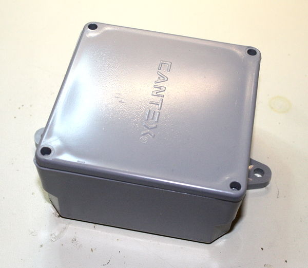
Figure 12-6. Arduino thermostat enclosure
Yes, the enclosure is really ugly. I won’t deny that. But for this project the main concern was wall mounting and having enough internal space for the components. The side mounting tabs will be removed and the front cover will be sanded and polished, which will help improve its appearance.
The controls are simple, with just an LCD display and a rotary encoder. It will all fit comfortably on the front cover panel. The planned layout of the front panel is shown in Figure 12-8.
The relay module will be mounted to the bottom of the enclosure, and the existing wires for the thermostat will enter through a hole in the bottom of the case. The RTC module will be mounted to the inside of the enclosure, and the DHT22 will be attached to the bottom so it will be exposed to the ambient environment. I elected to mount the DHT22 this way rather than put it inside because I didn’t want to drill an array of holes in the enclosure for air flow. An alternative would be to make a square hole just large enough for the DHT22 so it can mount inside but still have access to the outside air. Four screws will hold the thermostat to the wall.
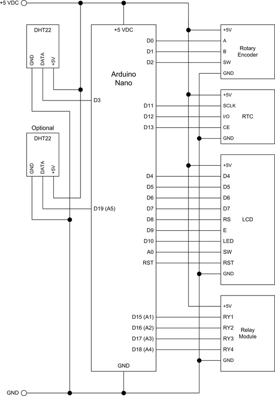
Figure 12-7. Arduino thermostat schematic
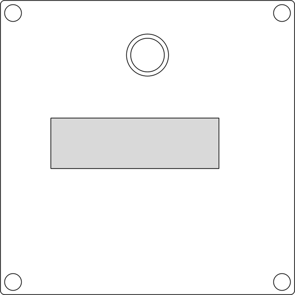
Figure 12-8. Arduino thermostat front panel layout
Schematic
There is no significant difference between the prototype and the final unit, so there is only one version of the schematic. The prototype is electrically identical to the final thermostat, but it uses an Arduino Uno rather than a Nano board (the AVR MCU is the same for both), mainly because that is what is mounted in the prototype fixture.
Notice that every single pin on the MCU is in use. The Arduino programming interface, via D0 and D1, is shared with the rotary encoder. So long as the rotary encoder is not in use this will not create a conflict.
You may also notice that the analog inputs have been pressed into service as digital I/O pins. This is completely normal, and if you refer back to Chapter 2 and Chapter 3 you can see how the ATmega328 port used for analog input (the C port) is also a standard discrete digital I/O port. By referring to the pins as D14 through D19 we can access these like any of the other digital I/O pins. Of course, the analog inputs are now unavailable, but the thermostat doesn’t use any analog input (except for the A0 pin, which is used by the LCD shield), so it’s not a problem.
Tip
Just because the Arduino convention is to assign functionality like analog input to specific pins doesn’t mean the pins can’t be used for something else. That’s just how the folks at Arduino.cc decided to name them. Since an Arduino board is a breakout for the MCU with nothing between the board’s pins and the MCU IC itself, what really determines what a pin can or cannot do is the MCU, not the labels on the PCB.
Software
This is a software-intensive project, but most of the software is involved with the user interface and the active profile. The actual control logic for thermostat operation is not all that complex.
Note
Remember that since the main emphasis of this book is on the Arduino hardware and related modules, sensors, and components, the software shown is intended only to highlight key points, not to present complete ready-to-run examples. The full software listings for the examples and projects can be found on GitHub.
On each iteration through the main loop the software will check for user input from the rotary encoder; update the current temperature and humidity data; and determine if the display should switch between screens, move to various settings, or change values. Interrupt handlers are used to capture the inputs from the rotary encoder. A high-level version of the software block diagram is shown in Figure 12-9.
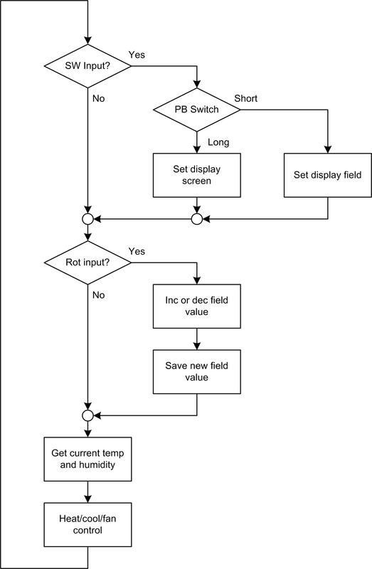
Figure 12-9. Arduino thermostat software block diagram
The main function blocks in Figure 12-9 give an indication of what to expect in terms of actual source code. In addition to the Thermostat.ino main file, there will be source modules for handling user inputs using interrupts, processing schedules (daytime, evening, or weekend), and updating the display.
The first thing the loop checks is the switch (SW) on the rotary encoder. This is the signal that indicates that the user wants to do something. The pushbutton switch in the rotary encoder is used to move between screens and between the fields in a screen. The type of action is determined by how long the switch is held down.
The interrupt handlers for the rotary encoder switch and the A/B inputs set flags in the global variables module. The main loop examines these to determine what display update action to take, if any. The interrupt handlers are not shown in Figure 12-9. They will be covered in “Software”.
The block labeled “Heat/cool/fan control” is the actual control logic of the thermostat. As stated earlier, this is a discrete-state hysteresis controller, also known as a “bang-bang” controller. Figure 12-10 shows the relationship between temperature, time, and hysteresis range in a timeline format for an A/C system. For heating, the operation is simply the inverse.
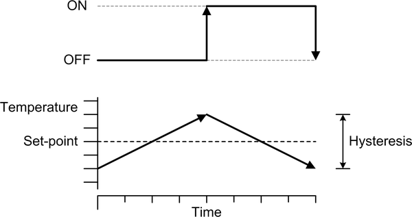
Figure 12-10. Time, temperature, and hysteresis range
Another way of representing this is shown in Figure 12-11. This graph shows hysteresis as a function of temperature. The message of both types of graphs is the same: a bang-bang control system (such as a thermostat) coupled with an on/off actuator (the heater or A/C unit) can never precisely hold a specific temperature. The system will always be at some point between the high and low ends of the hysteresis range.
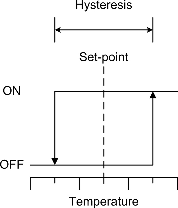
Figure 12-11. Effect of hysteresis on control system response
In a real system the rate at which the temperature increases or decreases will depend on the rate at which heat is being put into or taken out of the system, and how efficiently the heating or cooling equipment can add or extract heat. The upshot is that the heating and cooling times will almost never be the same, although both Figure 12-10 and Figure 12-11 might seem to imply that they are.
The thermostat’s control logic is shown in Figure 12-12. Notice that the heating and cooling are simply inverse operations. In an old-style electromechanical thermostat the H (hysteresis) term is established using a set screw on the bimetallic coil assembly. In software we can set this dynamically if we wish.
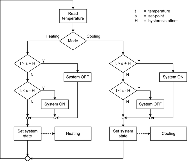
Figure 12-12. Thermostat control logic for heating and cooling
User Input/Output
The control input consists of a single rotary encoder. This might seem odd, but the encoder also has an integrated switch that is engaged when a user presses on the knob. The switch is used to move between display configurations (or screens, as I’m calling them). Each screen contains fields that display data or settings, and the rotary encoder is also used to move between the fields in each screen. The length of time the pushbutton switch in the rotary encoder is held down determines which action the software will take. A short press is a selection, and a long press commands the software to move to the next screen.
The display is the same type of 16 × 2 LCD used with the signal generator in Chapter 11. In this project it is premounted on a shield PCB. This simplifies the internal wiring. The LCD backlight is not enabled unless the control inputs are active. The small pushbutton switches on the LCD shield are not used, but they could be if you are willing to drill more holes through the front panel and find some type of extensions that a user could press. I elected to just ignore them.
Normally two primary screens will be displayed that alternate when the control inputs are not active. The first shows the current temperature readings, the setpoint, the operation mode, and the active profile (if any). The second screen shows the current date and time. Figure 12-13 shows the screens during normal operation. The symbols ^, v, and – are used to indicate if a reading is increasing, decreasing, or holding steady, respectively, relative to the previous reading.
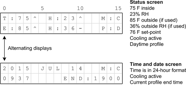
Figure 12-13. Normal operation screens
The fields shown in Figure 12-13 are defined in Table 12-1. In the second screen the “END” field shows the time at which the current profile will end.
| Field | Purpose |
|---|---|
T |
Current inside temperature, in degrees (F or C) |
E |
Exterior temperature (if enabled) |
H |
Humidity |
M |
Mode: A (auto), H (heat), C (cool), F (fan), or X (off) |
P |
Profile: D (day), N (night), W (weekend), or X (none) |
The screens shown in Figure 12-13 are purely informational with no modifiable fields. The temperature units may be either Celsius or Fahrenheit. The default is Fahrenheit. I elected to use 24-hour format for the time. It can be modified to accommodate 12-hour format (AM/PM) without too much effort.
The settings screen, shown in Figure 12-14, allows the user to enable or display the profile, and if the profile is disabled the user may manually adjust the temperature setpoint, temperature scale, hysteresis, and operation mode.
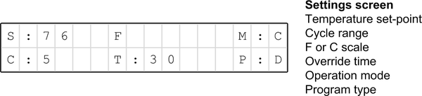
Figure 12-14. Settings screen
The settings screen is the primary control point for the thermostat. It is intentionally arranged to appear only when specifically invoked by a user. The fields used in the settings screen are listed in Table 12-2.
| Field | Purpose |
|---|---|
S |
Temperature setpoint |
C |
Cycle range (hysteresis, in degrees) |
F |
Either F or C for temp scale |
O |
Override time |
M |
Mode: A (auto), H (heat), C (cool), F (fan), or X (off) |
P |
Profile: D (day), N (night), W (weekend), or X (none) |
The main form of preset control for the thermostat is the user-defined profiles. Profiles are defined with the screen shown in Figure 12-15.
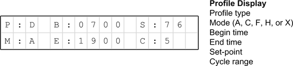
Figure 12-15. Profile editing screen
There are profiles for daytime, nighttime, and weekends; these are labeled D, N, and W, respectively. Rotating the encoder when the profile editing screen is first selected will step through the three profiles. Each profile has a start time and end time. In the case of the weekend (W) profile, the default start time is Friday at midnight, and the end time is Sunday at midnight. If the end time of a profile overlaps the start time of another, then the end time of the preceding profile always takes precedence. The fields used in the profile editing screen are listed in Table 12-3.
| Field | Purpose |
|---|---|
P |
Profile: D, N, W |
B |
Begin time |
E |
End time |
S |
Temperature setpoint |
C |
Cycle range (hysteresis) |
M |
Mode: A (auto), H (heat), C (cool), F (fan), or X (off) |
Navigating through the screens and fields does require some learning, but by using the length of the rotary encoder switch press and a tree structure the user can navigate the primary screens and the fields without getting lost. Figure 12-16 shows how the screens and fields respond to either a long or a short button press.
Figure 12-17 shows all four screens in one view. This might make it easier to visualize how the screens are arranged.
A long button press is defined as 1 second or longer. A short button press is 500 ms or shorter. The software uses an interrupt and a counter to monitor the button hold-down time.
Control Output
The control output consists of a quad relay module with four independent SPDT relays. It incorporates drivers for the relays and PCB terminal blocks, so connecting it to the existing thermostat wiring is straightforward. It can be seen in Figure 12-18. The common line is routed through the fourth (lower right in the diagram) relay.
In the block diagram in Figure 12-4 you will notice that the common line from the existing HVAC system is also routed through one of the relays. This is a fail-safe measure. If the thermostat loses power the relay with the common line drops out, and none of the other functions of the HVAC can be enabled. All the external HVAC control voltage lines, including the common return, are connected to the C and NO (common and normally open) terminals of the relays.
Prototype
The prototype for this project is comprised of an Arduino Uno, a pair of terminal block extensions, and an LCD shield. These are essentially the same components that will be packaged in an enclosure later on (the Nano and the Uno use the same ATmega328 MCU).
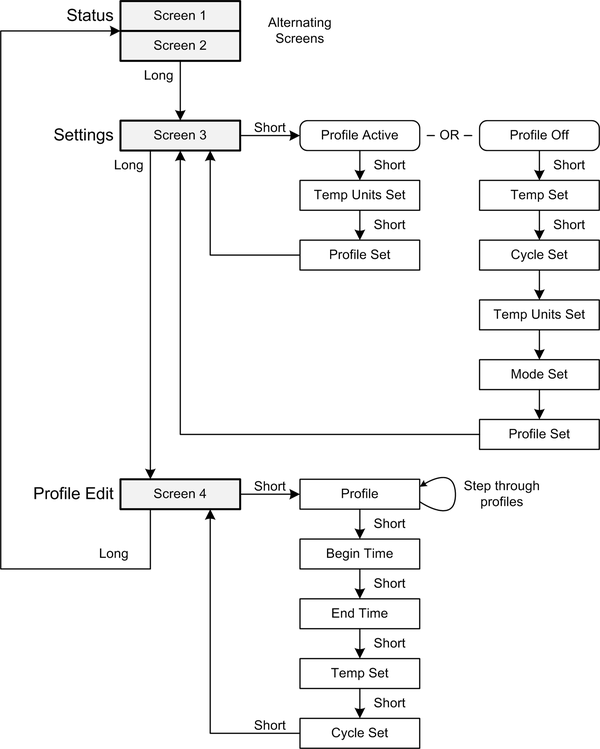
Figure 12-16. Thermostat screen and field navigation
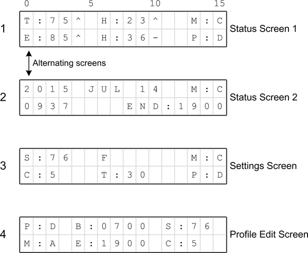
Figure 12-17. The four screens used by the thermostat
I’m reusing the Arduino-on-a-board that was used in Chapter 11 for the signal generator, but I could also have used the Duinokit introduced in Chapter 10. I elected to give the board another mission because it’s small enough to mount on the wall next to the existing thermostat during testing. The prototype is shown in Figure 12-18.
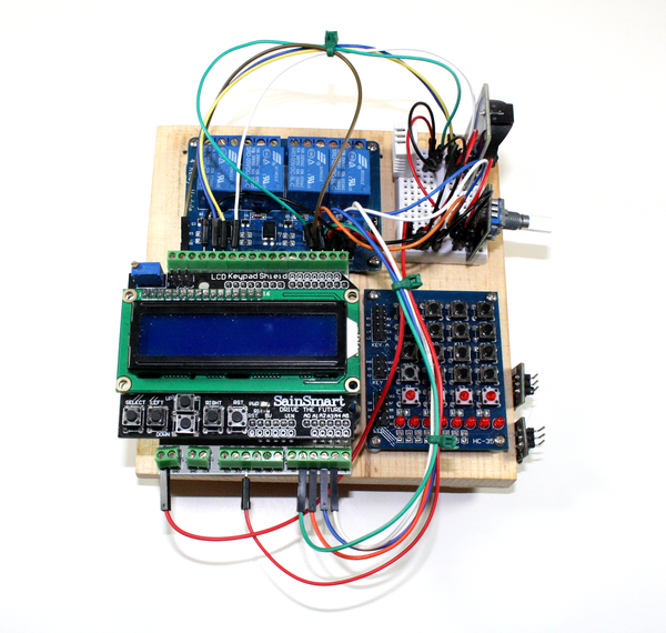
Figure 12-18. Arduino thermostat prototype
The prototype uses a slightly different, but electrically equivalent, set of parts to the final unit. The LCD shield is the same as the final unit will use, but the Arduino is an Uno whereas the final unit will use a Nano. In Figure 12-18 you can see the rotary encoder, the RTC module, and the DHT22 sensor on the small solderless breadboard module. The parts list for the prototype is given in Table 12-4.
| Quantity | Description |
|---|---|
1 |
Arduino Uno (or equivalent) |
1 |
LCD 16 × 2 display shield |
1 |
DS1302 real-time clock module |
1 set |
Screw terminal adapters |
1 |
Quad relay module |
1 |
DHT22 temperature/humidity sensor |
1 |
KEYES KY-040 rotary encoder module |
DHT22 Sensor
For temperature and humidity sensing we will use the DHT22 device, which is the same device used with the GreenShield in Chapter 10. In the final version the DHT22 sensor will be connected to the Arduino Nano with leads attached to screw terminals. The pinout of the DHT22 is shown in Figure 12-19.

Figure 12-19. DHT22 sensor pinout
A 1K ohm pull-up will be used on the data line, as recommended in the datasheet (available from Adafruit, SparkFun, and other locations). In the prototype, the DHT22 will be connected using a small solderless breadboard block on the wood base, as can be seen in Figure 12-18.
Rotary Encoder
The primary (and only) control input is a KEYES KY-040 module (see Chapter 9 for information about KEYES modules) with a Bonatech rotary encoder, similar to an Alps EC11 part. The module is shown in Figure 12-20, and the pinout is shown in Figure 12-21.
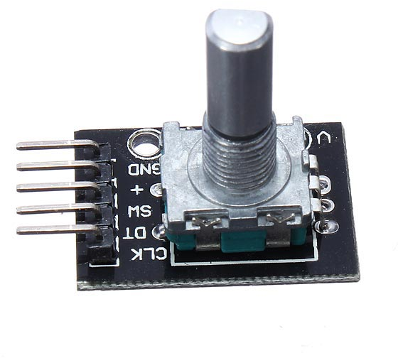
Figure 12-20. Rotary encoder module
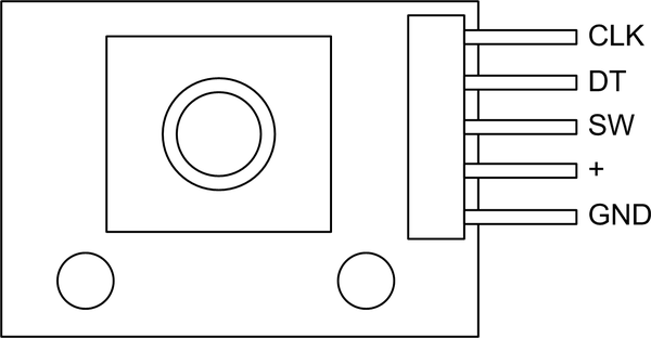
Figure 12-21. Rotary encoder module pin functions
The rotary encoder module circuit is simple, as shown in Figure 12-22. The encoder contains an internal switch that is engaged when the shaft is pressed in, and the three signal lines use 10K pull-up resistors. The pins labeled CLK and DT correspond to the A and B signals (respectively) found in most software examples and descriptions of simple quadrature rotary encoders.
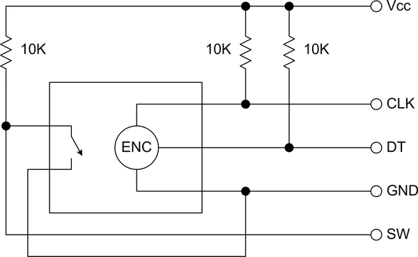
Figure 12-22. Rotary encoder module schematic
The rotary encoder’s integrated switch is used to change between display screens, and also for various user-modifiable items on each screen. It and the rotary encoder itself are the only two control inputs. The internal switch is normally open.
Real-Time Clock Module
The thermostat needs to be able to keep time in order to determine which thermal profile to use. A real-time clock (RTC) module based on a DS1302 IC is used for this purpose. The RTC module is really nothing more than a carrier for the DS1302 IC, a crystal, and a battery. Figure 12-23 shows a schematic of the RTC module. The pinout is self-explanatory.
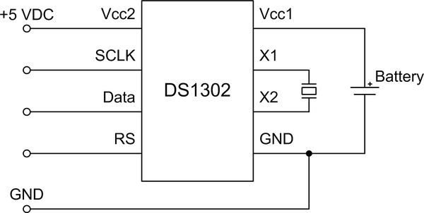
Figure 12-23. RTC module schematic
A library for the DS1302 is available from the Arduino Playground. The thermostat will use this rather than create a new library from scratch.
LCD Shield
The LCD shield, which can be seen in Figure 12-18 and is described in Chapter 8, is a common and readily available shield. It is the largest consumer of digital I/O pins on the Nano. In this application the shield was selected because it incorporates a potentiometer for contrast and a control transistor for the display backlight. It also connects directly to the underlying Arduino, thus eliminating wiring like that used in the signal generator in Chapter 11.
Software
The thermostat software is straightforward, and like most embedded software it is designed to run continuously with a primary loop. Unlike the other examples presented so far, the thermostat utilizes interrupts to handle a rotary encoder. Implementing an interrupt handler with an Arduino isn’t particularly difficult, and interrupts are by far the best way to deal with asynchronous events from the real world.
Source Code Organization
As with the other projects in this book, the source code is organized as a
set of source files (see Table 12-5). These include the primary
module with the setup() and loop() functions, a module for global
variables, and the logic for controlling the HVAC functions in accordance
with user-defined heating and/or cooling “programs.” The display module
borrows from work already done for the signal generator in Chapter 11,
and the interface module, tstat_iface.cpp, also includes the interrupt
handler for the rotary encoder.
| Module | Function |
|---|---|
Thermostat.ino |
Primary module containing |
tstat.h |
Constant definitions ( |
tstat_ctrl.cpp |
HVAC control logic |
tstat_ctrl.h |
Include file |
tstat_gv.cpp |
Global variables |
tstat_gv.h |
Include file |
tstat_iface.cpp |
Control input processing |
tstat_iface.h |
Include file |
tstat_lcd.cpp |
LCD functions |
tstat_lcd.h |
Include file |
tstat_util.cpp |
Utility functions |
tstat_util.h |
Include file |
Software Description
The software can be divided into three functional sections: user interface, control logic, and display management. The user interface functions, contained in the source module tstat_iface.cpp, provide the functionality to read the rotary encoder and navigate the display screens. tstat_lcd.cpp contains the LCD display handling functions. The source module tstat_ctrl.cpp provides the functionality for temperature and humidity sensing via the DHT22 sensor, the controller logic, and the user-defined programs.
Various libraries are used with this project for the DS1302 RTC, the rotary encoder, time and date functions, and the AVR’s timer 1 peripheral. These are listed in Table 12-6. This is one of the nice things about working with the Arduino: if you need a library to use a particular module, sensor, or shield, chances are someone, somewhere, has taken the time to create it so that you don’t have to.
| Name | Function | Author |
|---|---|---|
Time |
Time functions |
Michael Margolis |
DS1302RTC |
RTC class |
Timur Maksimov |
ClickEncoder |
Rotary encoder class |
Peter Dannegger |
TimerOne |
Timer 1 class |
Lex Talionis |
These libraries can be found in the Arduino Playground and on GitHub. Be sure to read the included documentation and the source code to gain a better understanding of what the code is doing and how to configure it if necessary. The DHT22 library is the same one that was used with the GreenShield in Chapter 10.
The file tstat.h contains the global definitions used by the other modules. These follow the pin assignments shown in Figure 12-7, illustrated in Example 12-1.
Example 12-1. tstat.h I/O definitions
#define ROTENC_A 0#define ROTENC_B 1#define ROTENC_SW 2#define LCD_D4 4// Predefined by the LCD shield#define LCD_D5 5//#define LCD_D6 6//#define LCD_D7 7//#define LCD_RS 8//#define LCD_E 9//#define LCD_LED 10//#define LCD_SW A0//#define RTC_SCLK 11#define RTC_IO 12#define RTC_CE 13#define RY1 15// A1#define RY2 16// A2#define RY3 17// A3#define RY4 18// A4#define DHT1 3// Internal DHT22#define DHT2 19// A5, external DHT22
The function setup() in Thermostat.ino, shown in Example 12-2, initializes
the LCD, displays some startup messages, checks the RTC module, and displays
the first screen.
Example 12-2. setup() function
voidsetup(){lcd->begin(16,2);// Set the dimensions of the LCDTitleDisp("Initializing...","",1000);lcd->clear();if(rtc->haltRTC())lcd->("Clock stopped!");elselcd->("Clock working.");lcd->setCursor(0,1);if(rtc->writeEN())lcd->("Write allowed.");elselcd->("Write protected.");delay(2000);// Setup time librarylcd->clear();lcd->("RTC Sync");setSyncProvider(rtc->get);// The function to get the time from the RTClcd->setCursor(0,1);if(timeStatus()==timeSet)lcd->(" Ok!");elselcd->(" FAIL!");delay(1000);TitleDisp("Initialization","complete",1000);curr_screen=0;Screen1();disptime=millis();}
The loop() function in Thermostat.ino isn’t complicated, as you can see from
Example 12-3. Most of the work
takes place when the rotary encoder is in use and when the software is
retrieving temperature and humidity data and executing the control functions
in tstat_ctrl.cpp.
Example 12-3. Thermostat main loop function
voidloop(){// Get current date and time from RTCRTCUpdate();if(input_active){HandleInput();}else{// Toggle between screen 1 and screen 2if((millis()-disptime)>MAX_DISP_TIME){if(curr_screen){Screen1();curr_screen=0;disptime=millis();}else{Screen2();curr_screen=1;disptime=millis();}}}GetTemps();SystemControl();}
When the encoder is not in use the display will alternate between screens
1 and 2, which show the current conditions and operating state and the date and time, respectively. When the encoder is used the input_active flag is set
to true, and it will remain true until the user returns to screen 1 by
pressing the encoder knob to engage the pushbutton switch. Notice that the
system control is still active while the input screens are in use.
Testing
Testing is a three-step process, and this section applies to both the prototype and the final unit. The first step involves setting the date and time in the RTC. This is done by changing to the time and date setup screen using the encoder pushbutton. After returning to the main displays, the correct time and date should appear. The next step involves setting the target temperature, the hysteresis range (the C parameter in the display), and the operation mode. I started by verifying that I could manually enable the system fan, and then entered a temperature setpoint and set the mode. You will want to watch the display and verify that the system stops heating or cooling when it has reached a temperature equal to the setpoint plus or minus one-half of the cycle (hysteresis) range.
Lastly, you should step through the profiles and set each one up the way you think is best for your situation. Remember that a conflict between the end time of one profile and the start of another is resolved by honoring the end time of a preceding profile, not the start time of a subsequent profile.
You should keep an eye on the operation of the thermostat over a period of a couple of weeks. It will probably require some fine-tuning to get the times and setpoints established for the most efficient operation. If you have built a GreenShield you can use it to log the temperature and humidity to capture performance data for the thermostat. A simple Python script will work nicely to query the GreenShield at regular intervals to collect data.
Final Version
The final version of the thermostat differs from the prototype in a few ways physically, but it is otherwise identical in terms of both function and signal connections. The three primary differences are the use of Nano board, a bare LCD module rather than an LCD shield, and an enclosure to mount it all into. The parts list for the final version of the thermostat is given in Table 12-7.
| Quantity | Description |
|---|---|
1 |
Arduino Nano (or equivalent) |
1 |
Screw terminal prototype board |
1 |
16 × 2 LCD display module |
1 |
Quad relay module |
1 |
DHT22 temperature/humidity sensor |
1 |
KEYES KY-040 rotary encoder module |
1 |
Real-time clock module |
1 |
Plastic enclosure |
Assembly
The final assembly mainly consists of mounting the components in and on the enclosure. But before that, the enclosure itself went through some changes. The embossed lettering was sanded off the top cover, the side mounting tabs were removed, and holes were cut and drilled for the display and the rotary encoder. Holes were also drilled into the bottom of the enclosure for mounting screws and the existing heater and A/C control wires. The case was painted a nice neutral shade of ivory after all the sanding, drilling, and cutting was done.
I used a screw terminal prototype shield to hold the Nano board, and wired the Nano’s pins to the appropriate terminals and pin headers. Figure 12-24 shows the topside view of the Nano’s prototype shield, along with the LCD shield, the rotary encoder, and the RTC module. The RTC module will be mounted to the inside of the enclosure.
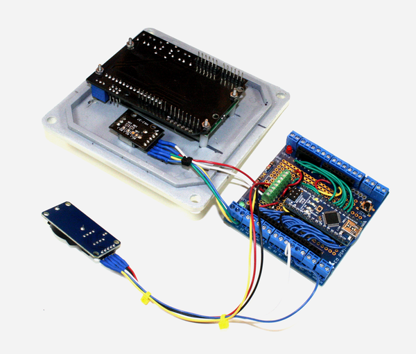
Figure 12-24. Nano prototype board and other top cover components
As I elected to keep all the wiring on the top of the prototype shield, the bottom of the shield is nothing but soldered pads. I used the smallest gauge of insulated stranded wire that I had available (28-gauge 7-strand) without resorting to wire-wrap wire. Solid 30 AWG wire with Kynar insulation is great for wire-wrap construction, but it can be less than ideal for something like this.
The big advantage of the screw terminal prototype shield is the ease with which wires to or from other components may be connected to the terminals. In the case of the thermostat this includes the DHT22 sensor, the real-time clock module, the relay module, and the rotary encoder.
Figure 12-25 shows what the enclosure looked like after its makeover. The LCD shield and the rotary encoder are already mounted. What isn’t shown is the DHT22 sensor, which is mounted on the outside of the bottom of the enclosure. You might also notice that the cover screws aren’t installed.
The small hole to the upper left of the LCD window is an access hole for the trim potentiometer on the LCD shield to set the display contrast. The LCD window will get some edge trim as the very last step, and a clear plastic cover might also be a good idea. Yes, it looks like something from an industrial plant, but as I said before, how it looks has no bearing on how it works. The gold knob is there (if you can see the image in color) because that was the only knob I had available at the time that didn’t have a pointer molded into it.
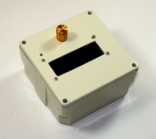
Figure 12-25. Almost finished thermostat enclosure
The quad relay module is mounted to the bottom of the enclosure. The RTC module is mounted to an interior side of the box. Figure 11-25 shows how things are arranged in the enclosure. The existing HVAC wiring is brought in through an access hole in the bottom of the enclosure. Note that the hole is offset vertically from center to allow clearance for the relay module.
It’s a tight fit, to be sure, but it does all fit. There are still several steps necessary before closing it up and turning it loose:
-
Locate the mounting screw locations on the wall and drill holes.
-
Pull the existing HVAC control wires through the bottom hole and mount the enclosure to the wall.
-
Connect the HVAC wires to the relay module.
-
Connect the power source and check the display.
-
Attach the cover to the enclosure.
Assuming that the software was already loaded onto the Nano, the thermostat should now be operational. There is no power switch, so it will start functioning as soon as the power is connected. The display backlight should remain active for 15 seconds after power is applied, so you may need to turn the encoder knob slightly if it has timed out and turned off.
![final_assy]](http://imgdetail.ebookreading.net/hardware/2/9781491934319/9781491934319__arduino-a-technical__9781491934319__assets__aian_1226.png)
Figure 12-26. Thermostat internal components
The enclosure comes with a rubber gasket, which you can use if you think it is necessary. I used it simply because it allows for a snug fit of the cover and gives a bit more space inside for the components, but I’m not worried about rain getting into the unit.
Testing and Operation
Testing consists of using the encoder to step through the display screens and verify that the long and short switch sensing is working correctly. You will need to set the parameters again, since loading the software doesn’t load the EEPROM, just the flash program memory. If the installed unit appears to operate correctly then you can start setting it up for your particular environment and preferences.
I would suggest something simple to begin with. Just controlling the heating or cooling is a good place to start. After you are satisfied that the unit is working as it should, then you might want to try setting up daytime/nighttime profiles and see how that works. As you gain more experience with the unit you can incorporate the humidity and cycle time settings. A device like this requires some amount of “tuning” to get it set so it will integrate effectively with your environment.
Cost Breakdown
One of the objectives of this project was to use off-the-shelf boards and modules as much as possible. This not only saved time and effort, but also helped hold down the cost (custom PCBs are not inexpensive). Build-wise, this project required much less effort than the signal generator in Chapter 11. Table 12-8 lists the primary components.
| Quantity | Item | Source | Unit price | Extendeda |
|---|---|---|---|---|
1 |
Arduino Nano |
SainSmart |
$14.00 |
$14.00 |
1 |
Screw terminal prototype shield |
Adafruit |
$15.00 |
$15.00 |
1 |
RTC module |
DealeXtreme |
$2.00 |
$2.00 |
1 |
Rotary encoder module |
Various |
$6.00 |
$6.00 |
1 |
LCD display shield |
SainSmart |
$10.00 |
$10.00 |
2 |
DHT22 sensors |
Adafruit |
$10.00 |
$20.00 |
1 |
Quad relay module |
SainSmart |
$7.00 |
$7.00 |
1 |
Electrical enclosure |
Home Depot |
$7.00 |
$7.00 |
a The extended amount is the total cost of each line item for a given quantity. | ||||
Total parts cost = $81.00
Note that KEYES modules, like the KY-040 rotary encoder, are often found in kits of modules. They can be purchased as single items from vendors on both eBay and Amazon, but picking up one of the kits is a better bargain.
As with the other example projects in this book, you can probably do better price-wise than what is shown in Table 12-8 by shopping around and doing some bargain hunting. I’ve seen Nano-type boards going for as little as $5, and DHT22 sensors in the $7 to $8 range.
Next Steps
This project is an example of the limitations that you can encounter when trying to create complex devices using only off-the-shelf shields and modules. If I were to create a Version 2 of the thermostat I would build a custom PCB that would contain everything on one board. Like the GreenShield from Chapter 10 it would have on-board relays, and a power supply would be incorporated as well.
This design is also a prime candidate for an I/O multiplexer like the MPC23017 used in the Switchinator PCB in Chapter 10. The LCD display can be controlled via an MPC23017. Adafruit sells a version of the display shield with an MPC23S17, which is the SPI version of the IC.
Additionally, I would use surface-mount parts for everything except perhaps the relays, the DHT22, and the terminal blocks. I would think that the relays could be downsized a bit, perhaps even to surface-mount parts, since they don’t really need to handle a lot of current through the contacts. With some careful design and parts selection the size of the entire PCB could be significantly reduced.
Some nice-to-have features that simply won’t fit in the current design include a Bluetooth or WiFi interface, a microSD flash card carrier for long-term data logging, and perhaps some additional LEDs for the front panel. As it stands, the Arduino thermostat is almost an Internet of Things (IoT) device, but it will require some redesign and enhancement to get it all the way there. Of all the things touted as IoT devices, a thermostat might make the most sense. I’m not convinced that letting the coffee maker or the microwave oven talk to the refrigerator is a good idea.
Resources
Table 12-9 lists the distributors and vendors where I purchased the parts for the thermostat. As with all of the example projects in this book, there are multiple sources for most of the components. These are simply the ones I used at the time I made the purchases.
| Distributor/vendor | URL |
|---|---|
Adafruit |
|
DealeXtreme (DX) |
|
DFRobot |
|
SainSmart |
I found the enclosure in the electrical section of my local Home Depot store, but you can find similar electrical enclosures at any electrical supply house or well-stocked hardware store.