
Chapter 3. Container Networking Basics
Now that we have discussed networking basics and Linux networking, we will discuss how networking is implemented in containers. Like networking, containers have a long history of developments. This chapter will review that history, discuss the various options for running containers, and the networking setup available. The industry, for the time being, has settled on Docker as the container runtime standard. With that, we will dive into the Docker Networking Model, how the Container Network interface differs from the Docker Network model, and end the chapter with examples of networking modes with docker containers.
Introduction to Containers
In this section we will discuss the evolution of running applications that has led us to containers. Some, rightfully, will talk about containers as not being real. They are yet another abstraction of underlying technology in the OS kernel. Being technically right misses the point of the technology and leads us nowhere further down the issues of solving the hard problem that is application management and deployment.
Application
Running applications has always had its challenges. There are many ways to serve applications nowadays, in the cloud, on-prem, and of course, containers. Versions of libraries, shared drives, deployments, and versions of the application itself, are just a few of the problems. For the longest time, developers of applications had to deal with these issues. Bash scripts, deployment tools all have their drawbacks and issues. Every new company has its way of deploying applications, so every new developer had to learn these. Separation of duties, permissions controls, maintaining system stability, required System administrators to limit access to developers for deployments. Sysadmins also manage multiple applications on the same host machine to drive up that machine’s efficiency. Thus creating contention between Developers wanting to deploy new features and System Administrators wanting to maintain the whole ecosystem’s stability.
A general-purpose OS supports as many types of applications as possible, so its kernel includes all kinds of drivers, protocol libraries, and schedulers. Figure 3-1 shows one machine, one Operating system, but there are many ways to deploy an application to that host. Application deployment is a problem for any organization to try to solve.
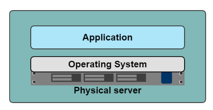
Figure 3-1. Application Server
From a networking perspective, with one Operating system, there is one TCP/IP stack. That single stack creates issues with port conflicts on the host machine. System administrators host multiple applications on the same machine to increase the machine’s utilization, and each application will have to run on its port. So now, the System administrators, the application developers, and the network engineers have to coordinate all of this together. One more task to add to the deployment checklist, troubleshooting guides, and all the IT requests. Hypervisors became a way to increase one host machine’s efficiency and remove one Operating System and networking stack issues.
Hypervisor
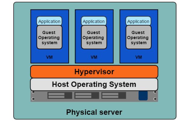
Figure 3-2. Hypervisor
A Hypervisor emulates hardware resources, CPU, memory, from a host machine to create guest operating systems or Virtual Machines. In 2001 VMware released its x86 Hypervisor; earlier versions include IBM’s z/architecture and FreeBSD jails. 2003 saw the release of Xen, the first opensource Hypervisor, and in 2006 Kernel-based Virtual Machine, KVM, was released. The Hypervisor allows system administrators to share the underlying hardware with multiple guest operating systems; Figure 3-2 demonstrates this. This resource sharing increases the host machines’ efficiency, alleviating one of the sysadmins issues.
The Hypervisor also gave each application development team a separate networking stack, removing the port conflict issues on share systems. Team A’s Tomcat application can run on port 8080, while team b’s can also run on port 8080 since each application can now have its guest operating system with a separate network stack. Library versions, deployment, and other issues remain for the application developer. How can they package and deploy everything their application needs while maintaining the efficiency introduced by the Hypervisor and Virtual Machines? This concern led to the development of Containers.
Containers
In Figure 3-3, we can see the benefits of the containerization of applications; each container is independent. Application devs can use whatever they need to run their application without relying on underlying libraries or host operating systems. Each container also has its network stack. The container allows developers to package and deploy their applications while maintaining efficiencies for the host machine.
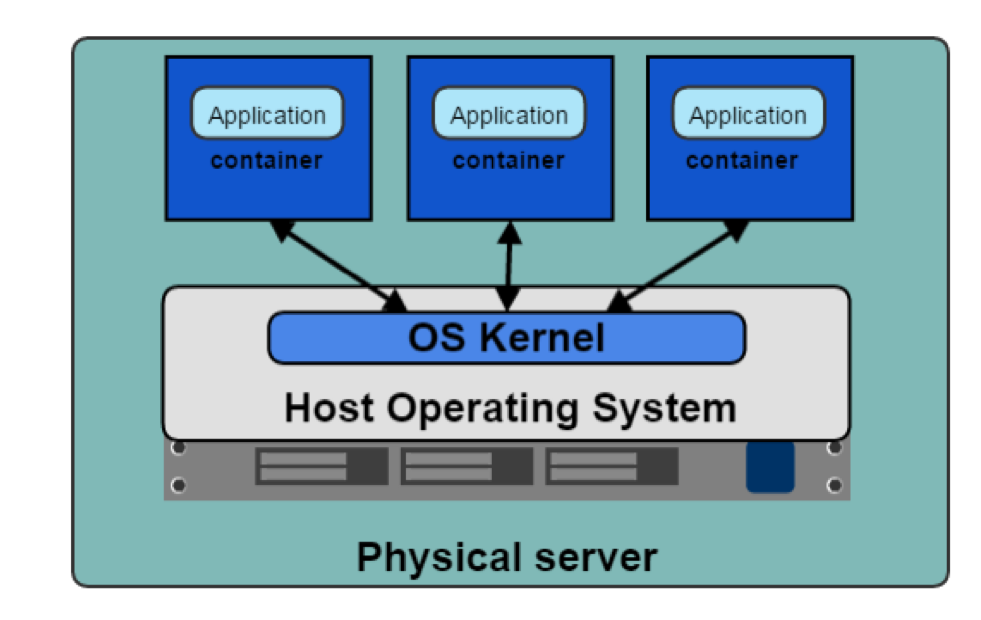
Figure 3-3. Containers running on Host OS
With any technology comes a history of changes, competitors, and innovations, and containers are no different. Below is a list of terms that can be confusing when first learning about containers. First, we will list the distinction between container runtimes, discuss each runtimes’ functionality, and show how they relate to Kubernetes. The functionality of container runtimes breaks down to “high level” and “low level.”
- Container
-
A running container image.
- Image
-
A Container image is the file that is pulled down from a Registry Server and used locally as a mount point when starting a container.
- Container Engine
-
A container engine is the piece of software that accepts user requests, command line options, pulls images, and from the end user’s perspective to run a container.
- Container Runtime
-
The container runtime is the low level piece of software in a container engine that deals with running a container.
- Base Image
-
A Starting point for containers images, to reduce build image sizes and complexity, users can start with a base images and make incremental changes on top of it.
- Image Layer
-
Repositories are often referred to as images or container images, but actually they are made up of one or more layers. Image layers in a repository are connected together in a parent-child relationship. Each image layer represents changes between itself and the parent layer.
- Image Format
-
Container Engines have their own container image format, LXD, RKT, and Docker.
- Registry
-
A Registry stores containers images and allows for users to upload, download and update container images.
- Repository
-
Repositories can be be equivalent to a container images. The important distinction is that repositories are made up of layers and metadata about the image, this is the manifest.
- Tag
-
A Tag is a user defined name that different versions of a container image.
- Container Host
-
The container host is the system that runs the container with a container engine.
- Container Orchestration
-
This is Kubernetes does! It dynamically schedules container workloads for a cluster of container hosts.
Note
cgroups and namespaces are Linux primitives to create containers; they are discussed in the next section.
An example of “Low” level functionality is creating cgroups and namespaces for containers, the bare minimum to run one. Developers require more than that when working with containers. They need to build and test containers and deploy them; these are considered a “high-level” functionality. Each container runtime offers various levels of functionality. Below is a list of high and low functionality.
Low-Level Container Runtime Functionality.
-
Creating containers
-
Running containers
High-level Container Runtime Functionality.
-
Container image format
-
Building container images
-
Managing container images
-
Managing instances of containers
-
Sharing container images
Over the next few pages, we will discuss runtimes that implement the above functionality. Each project below has its strengths and weaknesses to provide high and low-level functionality. Some are good to know about for historical reasons but no longer exist or have merged with other projects.
Low-Level Container Runtimes.
-
lxc - C API for creating Linux container
-
runc - Cli for oci compliant containers
High-level Container Runtimes.
-
containerd - Container runtime split off from Docker, a graduated Cloud Native Compute Foundation (CNCF) project
-
cri-o. - Container runtime interface using the Open Container Initiative, OCI, specification, an incubating CNCF project
-
Docker - Opensource container platform
-
lmctfy - Google containerization platform
-
rkt - CoreOs container specification
OCI
Open Container Initiative (OCI) promotes common, minimal, open standards and specifications for container technology.
The idea for creating a formal specification for container image formats and runtime allows a container to be portable across all major operating systems and platforms to ensure no undue technical barriers. The three values guiding the OCI project are:
- Composable
-
Tools for managing containers should have clean interfaces. They should also not be bound to specific projects, clients, or frameworks and work across all platforms.
- Decentralized
-
The format and runtime should be well-specified and developed by the community, not one organization
-
Another goal of the OCI project is independent implementations of tools to run the same container.
-
- Minimalist
-
The OCI spec strives to do several things well, be minimal and stable, and enable innovation and experimentation.
Docker donated a draft for the base format and runtime. They also donated code for a reference implementation to the OCI. Docker took the contents of the libcontainer project and made it run independently of Docker, and donated it to the OCI project. That codebase is runc, can be found at https://github.com/opencontainers/runc.
Let’s discuss several early container initiatives, their capabilities. This section will end with where the Kubernetes is with Container runtimes and how they work together.
lxc
Linux Containers, LXC, was created in 2008. LXC combines cgroup and namespaces to provide an isolated environment for running applications. LXC’s goal is to create an environment as close as possible to a standard Linux without the need for a separate kernel. LXC has separate components; the liblxc library, several programming languages bindings, python3/2, Lua, Go, Ruby, Haskell, A set of standard tools and container templates.
runc
Runc is the most widely used container runtime developed initially as part of Docker and was later extracted as a separate tool and library. Runc is a command-line tool for running applications packaged according to the Open Container Initiative, OCI, format and is a compliant implementation of the OCI spec. Runc uses libcontainer, which is the same container library powering a Docker engine installation. Before version 1.11, the Docker engine was used to manage volumes, networks, containers, images, etc. Now, Docker architecture has several components, and runc features include:
-
Full support for Linux namespaces, including user namespaces
-
Native support for all security features available in Linux:
-
SELinux, Apparmor, seccomp, control groups, capability drop, pivot_root, uid/gid dropping, etc.
-
-
Native support of Windows 10 containers
-
Planned native support for the entire hardware manufacturers’ ecosystem.
-
A formally specified configuration format, governed by the Open Container Initiative under the Linux Foundation.
containerd
Containerd is a high-level runtime that was split off from Docker. Containerd is a background service that acts as an API facade for various container runtimes and OS. Containerd has various components that provide it is high-level functionality. Containerd is a service for Linux and Windows that manages its host system’s complete container lifecycle, image transfer, storage, container execution, and network attachment. Containerd’s client CLI tool is ctr, and it is for development and debugging purposes for direct communication with containerd. Containerd-shim is the component that allows for daemonless containers. It resides as the parent of the container’s process to facilitate a few things. Containerd allows the runtimes, i.e., runc, to exit after it starts the container. This way, we do not have to have the long-running runtime processes for containers. It also keeps the standard io and other file descriptors open for the container if containerd and Docker die. If the shim does not run, then the pipes’ parent side would be closed, and the container would exit. Containerd-shim also allows the container’s exit status to be reported back to a higher level tool like Docker without having the container’s process’s actual parent and do await.
lmctfy
Google started lmctfy as its opensource Linux container technology in 2013. Lmctfy is a high-level container runtime that provides creation and deletion of containers but is no longer actively maintained and lastly was porting over to libcontainer, which is now containerd. Lmctfy provided an API driven configuration without developers worrying about the details of cgroups and namespace internals.
rkt
Rkt Started at CoreOS as an alternative to Docker in 2014. It is written in Go and uses pods as its basic compute unit and allows for a self-contained environment for applications. rkt’s native image format is the App Container Image (ACI), defined in the App Container spec; this is deprecated in favor of the OCI format and specification support. It supports the CNI specification and can run Docker images and OCI images. The rkt project was archived in Feb 2020 by the maintainers.
docker
Docker, released in 2013, solved many of the problems that developers had running containers end-to-end. It has all this functionality for developers to create, maintain, and deploy containers:
-
Container image format
-
Building container images
-
Managing container images
-
Managing instances of containers
-
Sharing container images
-
Running containers
Figure 3-4 shows us how the architecture of the Docker engine and its various components. Docker began as a monolith application, building all the above functionality into a single binary known as the docker engine. The engine contained the docker client or CLI that allows developers to build, run, and push containers and images. Docker server runs as a daemon to manage the data volumes and networks for running containers. The client communicates to the server through the docker API. Containerd to manage the container lifecycle, and then runC for spawning the container process.
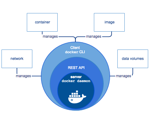
Figure 3-4. Docker Engine
In the past few years, Docker has broken apart this monolith into separate components. In order to run a container, the Docker engine creates the image, passes it to containerd. Containerd calls containerd-shim that uses runC to run the container. Then, containerd-shim allows the runtime (runC in this case) to exit after it starts the container: This way, we can run daemon-less containers because we do not have to have the long-running runtime processes for containers.
Docker provides a separation of concerns for application developers and system administrators. It allows the developers to focus on building their apps, and System admins focus on deployment. Docker provides a fast development cycle; to test new versions of golang for our web add, we can update the base image and run tests against it. Docker provides application portability between running on-premise, in the cloud, or any other Datacenter. Their motto is to Build, ship, run anywhere. A new container can quickly be provisioned for scalability and run more apps on one host machine, increasing that machine’s efficiency.
CRI-O
CRI-O is an OCI-based implementation of Kubernetes Container Runtime Interface while the OCI is a set of specifications that container runtime engines must implement. Redhat started the Container Runtime Interface (CRI) project in 2016 and in 2019 was contributed to the CNCF. CRI is a plugin interface that enables Kubernetes, via the kubelet, to communicate with any container runtime that satisfies the CRI interface. CRI-O development began in 2016 after the Kubernetes project introduced CRI, and CRI-O 1.0 was released in 2017. The CRI-O is a lightweight CRI runtime made as a Kubernetes specific high-level runtime built on gRPC and Protobuf over a Unix socket. Figure 3-5 points out where the CRI fits into the whole picture with the Kubernetes architecture. CRI-O provides stability in the Kubernetes project, with a commitment to passing Kubernetes tests.
Note
The first CRI implementation was the dockershim, which provided a layer of abstraction in front of the Docker engine.

Figure 3-5. CRI about Kubernetes
There have been many companies, technologies, and innovations in the container space. This section has been a brief history of that. The industry has landed on making sure the container landscape remains open, OCI project, for all to use across various ways to run containers. Kubernetes has helped shaped this effort as well with the adaption of the CRI-O interface. Understanding the components of the container is vital to all administrators of container deployments and developers using containers. A recent example of this importance is in Kubernetes 1.20, where dockershim support will be deprecated. The Docker runtime utilizing the dockershim for administrators is deprecated, but Developers can still Docker to build OCI compliant containers to run.
Now we will dive deeper into the container technology that powers them.
Container Primitives
No matter if you are using Docker or containerd, runc starts and manages the actual containers for them. In this section, we will review what runc takes care of for developers from a container perspective. Each of our containers has Linux primitives known as control groups and Namespaces. Figure 3-6 shows an example of what this looks like, cgroups control access to resources in the kernel for our containers, and namespaces are individual slices of resources to manage separately from the root namespaces, i.e., the host.

Figure 3-6. Namespaces and Control Groups
To help solidify these concepts, let us dig into control groups and namespaces a bit further.
Control Groups
Abbreviated cgroups is a Linux kernel feature that limits, accounts for, and isolates resource usage. Initially released in Linux 2.6.24, cgroups allow administrators to control different CPU systems and memory for particulate processes. Cgroups are provided through a pseudo-filesystems and are maintained the core kernel code in cgroupfs. Separate subsystems maintain various cgroups in the kernel listed below.
-
CPU - the process can be guaranteed a minimum number of CPU shares
-
memory - sets up memory limits for a process
-
disk I/O - and other devices are controlled via the devices cgroup subsystem
-
network - is maintained by net_cls nad marks packets leaving the cgroup.
lscgroup is a command-line tool that lists all the cgroup currently in the system.
Runc will create the cgroups for the container at creation time. Cgroup controls how much of a resource a container can use, while namespaces control what processes inside the container can see.
Namespaces
Namespaces are a feature of the Linux kernel that isolates and virtualize system resources of a collection of processes. Examples of virtualized resources:
-
PID namespace: Process ID, for process isolation.
-
net namespace: Managing network interfaces and a separate networking stack.
-
IPC namespace: Managing access to interprocess communication (IPC) resources.
-
mnt namespace: Managing filesystem mount points.
-
uts namespace: UNIX Time-Sharing, allows single hosts to have different host and domain names to different processes.
-
uid namespaces: User ID, Isolates process ownership with separate user and group assignments.
A process’s user and group IDs can be different inside and outside a user’s namespace. A process can have an unprivileged user ID outside a user namespace while at the same time having a user ID of 0 inside the container user namespace. The process has root privileges for execution inside the user namespace but is unprivileged for operations outside the namespace.
Below is an example of how to inspect the namespaces for a process. All information for a process is on
the /proc filesystem in Linux. PID 1’s PID namespace is 4026531836, listing out all the namespaces shows that
the PID namespace id’s matches.
vagrant@ubuntu-xenial:~$sudo ps -p1-o pid,pidns PID PIDNS14026531836 vagrant@ubuntu-xenial:~$sudo ls -l /proc/1/ns total 0 lrwxrwxrwx1root root0Dec1220:41 cgroup -> cgroup:[4026531835]lrwxrwxrwx1root root0Dec1220:41 ipc -> ipc:[4026531839]lrwxrwxrwx1root root0Dec1220:41 mnt -> mnt:[4026531840]lrwxrwxrwx1root root0Dec1220:41 net -> net:[4026531957]lrwxrwxrwx1root root0Dec1220:41 pid -> pid:[4026531836]lrwxrwxrwx1root root0Dec1220:41 user -> user:[4026531837]lrwxrwxrwx1root root0Dec1220:41 uts -> uts:[4026531838]
Figure 3-7 shows up that effectively these two Linux primitives allow application developers to control and managed their applications separate from the hosts and other applications either in containers or running natively on the host.
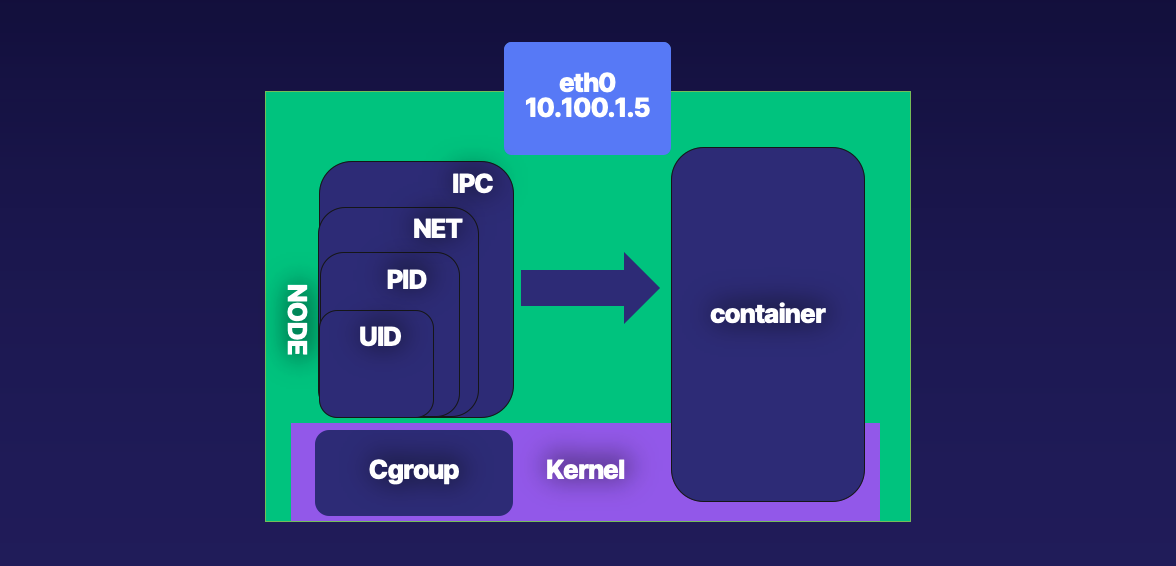
Figure 3-7. Cgroups and Namespaces with your powers combined
The below examples use Ubuntu 16.04 LTS; Xenial Xerus builds; If you want to follow along on your system, more information can be found in this book’s code repo. The repo contains the tools and configurations for building the Ubuntu VM and Docker containers. Let us get started with setting up and testing our namespaces.
Setting up Namespaces
Figure 3-8 outlines a basic container network setup. In the proceeding pages, we will walk through all the Linux commands that the low-level runtimes complete for container network creation.
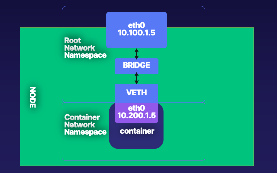
Figure 3-8. Root Network Namespace and Container Network Namespace
The following steps show how to create the networking setup shown in Figure 3-8.
-
Create a host with a root network namespace.
-
Create a new network namespace.
-
Create a veth pair.
-
Move one side of the veth pair into a new network namespace.
-
Address side of the veth pair inside the new network namespace.
-
Create a bridge interface.
-
Address bridge interface.
-
Attach bridge to the host interface.
-
Attach one side of the veth pair to the bridge interface.
-
Profit.
Below are all the Linux Commands needed to create the network namespace, bridge, veth pairs, and wire them together outline the above steps.
vagrant@ubuntu-xenial:~$echo1> /proc/sys/net/ipv4/ip_forward vagrant@ubuntu-xenial:~$sudo ip netns add net1 vagrant@ubuntu-xenial:~$sudo ip link add veth0typeveth peer name veth1 vagrant@ubuntu-xenial:~$sudo ip linksetveth1 netns net1 vagrant@ubuntu-xenial:~$sudo ip link add veth0typeveth peer name veth1 vagrant@ubuntu-xenial:~$sudo ip netnsexecnet1 ip addr add 192.168.1.101/24 dev veth1 vagrant@ubuntu-xenial:~$sudo ip netnsexecnet1 ip linksetdev veth1 up vagrant@ubuntu-xenial:~$sudo ip link add br0typebridge vagrant@ubuntu-xenial:~$sudo ip linksetdev br0 up vagrant@ubuntu-xenial:~$sudo ip linksetenp0s3 master br0 vagrant@ubuntu-xenial:~$sudo ip linksetveth0 master br0 vagrant@ubuntu-xenial:~$sudo ip netnsexecnet1 ip route add default via 192.168.1.100
Let’s dive into an example and outline each command.
The ip Linux command sets up and controls the network namespaces.
Note
More information for ip is at https://man7.org/linux/man-pages/man8/ip-netns.8.html
We have used vagrant and virtual box to create a fresh installation of Ubuntu for our testing purposes. Refer the book repo for the vagrantfile to reproduce this.
Note
Vagrant is a local Virtual Machine manager created by Hashicorp. It is available to download here. https://www.vagrantup.com/
Example 3-1. Ubuntu Testing Virtual Machine
$vagrant up Bringing machine'default'up with'virtualbox'provider...==> default: Importing base box'ubuntu/xenial64'...==> default: Matching MAC addressforNAT networking...==> default: Checkingifbox'ubuntu/xenial64'version'20200904.0.0'is up to date...==> default: Setting the name of the VM:advanced_networking_code_examples_default_1600085275588_55198==> default: Clearing any previouslysetnetwork interfaces...==> default: Available bridged network interfaces: 1)en12: USB 10/100 /1000LAN 2)en5: USB Ethernet(?)3)en0: Wi-Fi(Wireless)4)llw0 5)en11: USB 10/100/1000 LAN 2 6)en4: Thunderbolt 4 7)en1: Thunderbolt 1 8)en2: Thunderbolt 2 9)en3: Thunderbolt3==> default: When choosing an interface, it is usually the one thatis==> default: being used to connect to the internet.==> default: default: Which interface should the network bridge to?1==> default: Preparing network interfaces based on configuration... default: Adapter 1: nat default: Adapter 2:bridged==> default: Forwarding ports... default:22(guest)=>2222(host)(adapter 1)==> default: Running'pre-boot'VM customizations...==> default: Booting VM...==> default: Waitingformachine to boot. This may take a few minutes... default: SSH address: 127.0.0.1:2222 default: SSH username: vagrant default: SSH auth method: private key default: Warning: Connection reset. Retrying... default: default: Vagrant insecure key detected. Vagrant will automatically replace default: this with a newly generated keypairforbetter security. default: default: Inserting generated public key within guest... default: Removing insecure key from the guestifit's present... default: Key inserted! Disconnecting and reconnecting using new SSH key...==> default: Machine booted and ready!==> default: Checkingforguest additions in VM...==> default: Configuring and enabling network interfaces...==> default: Mounting shared folders... default: /vagrant=> /Users/strongjz/Documents/code/advanced_networking_code_examples
After vagrant boots our virtual machine, we can use vagrant to ssh into this VM.
$±|master U:2 ?:2 ✗|→ vagrant ssh Welcome to Ubuntu 16.04.7 LTS(GNU/Linux 4.4.0-189-generic x86_64)vagrant@ubuntu-xenial:~$
IP forwarding is an operating system’s ability to accept incoming network packets on one interface, recognize them for another, and pass them on to that network accordingly. When enabled, “IP forwarding” allows a Linux machine to receive incoming packets and forward them. A Linux machine acting as an ordinary host would not need to have IP forwarding enabled because it generates and receives IP traffic for its purposes. By default, it is turned off; let us enabled it on our Ubuntu instance.
vagrant@ubuntu-xenial:~$sysctl net.ipv4.ip_forward net.ipv4.ip_forward=0 vagrant@ubuntu-xenial:~$sudoecho1> /proc/sys/net/ipv4/ip_forward vagrant@ubuntu-xenial:~$sysctl net.ipv4.ip_forward net.ipv4.ip_forward=1
With our install of the Ubuntu instance, we can see that we do not have any additional network namespaces, so let us create one.
vagrant@ubuntu-xenial:~$ sudo ip netns list
ip netns allows us to control the namespaces on the server. Creating one is easy as typing ip netns add net1.
vagrant@ubuntu-xenial:~$ sudo ip netns add net1
As we work through this example, we can see the network namespace we just created.
vagrant@ubuntu-xenial:~$ sudo ip netns list
net1
Now that we have a new network namespace for our container will need a veth pair for communication between the root network namespace, and the container network namespace net1.
ip again allows administrators to create the veth pairs with a straightforward command. Remember from Chapter 2
veth come in pairs and act as a conduit between network namespaces, packets from one end are automatically forwarded
to the other.
vagrant@ubuntu-xenial:~$sudo ip link add veth0typeveth peer name veth1
The ip link list command verifies the veth pair creation.
Tip
The interfaces 4 and 5 are the veth pairs in the command output. We can also see which are paired with each other,
veth1@veth0 and veth0@veth1.
vagrant@ubuntu-xenial:~$ip link list 1: lo: <LOOPBACK,UP,LOWER_UP> mtu65536qdisc noqueue state UNKNOWN mode DEFAULT group default qlen 1 link/loopback 00:00:00:00:00:00 brd 00:00:00:00:00:00 2: enp0s3: <BROADCAST,MULTICAST,UP,LOWER_UP> mtu1500qdisc pfifo_fast state UP mode DEFAULT group default qlen 1000 link/ether 02:8f:67:5f:07:a5 brd ff:ff:ff:ff:ff:ff 3: enp0s8: <BROADCAST,MULTICAST,UP,LOWER_UP> mtu1500qdisc pfifo_fast state UP mode DEFAULT group default qlen 1000 link/ether 08:00:27:0f:4e:0d brd ff:ff:ff:ff:ff:ff 4: veth1@veth0: <BROADCAST,MULTICAST,M-DOWN> mtu1500qdisc noop state DOWN mode DEFAULT group default qlen 1000 link/ether 72:e4:03:03:c1:96 brd ff:ff:ff:ff:ff:ff 5: veth0@veth1: <BROADCAST,MULTICAST,M-DOWN> mtu1500qdisc noop state DOWN mode DEFAULT group default qlen 1000 link/ether 26:1a:7f:2c:d4:48 brd ff:ff:ff:ff:ff:ff vagrant@ubuntu-xenial:~$
Now let us move veth1 into the new network namespace created previously.
vagrant@ubuntu-xenial:~$sudo ip linksetveth1 netns net1
The ip netns exec. netns exec allows verifying the network
namespaces’ configuration. The output verifies that veth1 is now in the network namespace net.
vagrant@ubuntu-xenial:~$sudo ip netnsexecnet1 ip link list 4: veth1@if5: <BROADCAST,MULTICAST> mtu1500qdisc noop state DOWN mode DEFAULT group default qlen 1000 link/ether 72:e4:03:03:c1:96 brd ff:ff:ff:ff:ff:ff link-netnsid 0
Network namespaces are entirely separate TCP/IP stacks in the Linux kernel. Being a new interface and in a new network namespaces, the veth interface will need IP addressing in order to carry packets from the net1 namespace to the root namespace and beyond the host.
vagrant@ubuntu-xenial:~$sudo ip netnsexecnet1 ip addr add 192.168.1.100/24 dev veth1
As with host networking interfaces, they will need to be “turned on.”
vagrant@ubuntu-xenial:~$sudo ip netnsexecnet1 ip linksetdev veth1 up
The state has now transitioned to LOWERLAYERDOWN. The status NO-CARRIER points in the right direction. Ethernet
needs a cable to be connected; our upstream veth pair is not on yet either. The veth1 interface
is up and addressed but effectively still “unplugged.”
vagrant@ubuntu-xenial:~$sudo ip netnsexecnet1 ip link list veth1 4: veth1@if5: <NO-CARRIER,BROADCAST,MULTICAST,UP> mtu1500qdisc noqueue state LOWERLAYERDOWN mode DEFAULT group default qlen1000link/ether 72:e4:03:03:c1:96 brd ff:ff:ff:ff:ff:ff link-netnsid 0
Let us turn up the veth0 side of the pair now.
vagrant@ubuntu-xenial:~$sudo ip linksetdev veth0 up vagrant@ubuntu-xenial:~$sudo ip link list 5: veth0@if4: <BROADCAST,MULTICAST,UP,LOWER_UP> mtu1500qdisc noqueue state UP mode DEFAULT group default qlen 1000 link/ether 26:1a:7f:2c:d4:48 brd ff:ff:ff:ff:ff:ff link-netnsid 0
Now the veth pair inside the net1 namespace is UP.
vagrant@ubuntu-xenial:~$sudo ip netnsexecnet1 ip link list 4: veth1@if5: <BROADCAST,MULTICAST,UP,LOWER_UP> mtu1500qdisc noqueue state UP mode DEFAULT group default qlen 1000 link/ether 72:e4:03:03:c1:96 brd ff:ff:ff:ff:ff:ff link-netnsid 0
Both sides of the veth pair report up; we need to connect the root namespace veth side to the bridge interface. Make sure to select the interface you’re working with, in this case it enp0s8, it may be different for others.
vagrant@ubuntu-xenial:~$sudo ip link add br0typebridge vagrant@ubuntu-xenial:~$sudo ip linksetdev br0 up vagrant@ubuntu-xenial:~$sudo ip linksetenp0s8 master br0 vagrant@ubuntu-xenial:~$sudo ip linksetveth0 master br0
We can see that the enp0s8 and veth0 report are part of the bridge br0 interface, master br0 state up.
Next, let us test connectivity to our network namespace.
vagrant@ubuntu-xenial:~$ping 192.168.1.100 -c 4 PING 192.168.1.100(192.168.1.100)56(84)bytes of data. From 192.168.1.10icmp_seq=1Destination Host Unreachable From 192.168.1.10icmp_seq=2Destination Host Unreachable From 192.168.1.10icmp_seq=3Destination Host Unreachable From 192.168.1.10icmp_seq=4Destination Host Unreachable --- 192.168.1.100 ping statistics ---4packets transmitted,0received, +4 errors, 100% packet loss,time6043ms
Our new network namespace does not have a default route, so it does not know where to route our packets for the ping requests.
vagrant@ubuntu-xenial:~$sudo ip netnsexecnet1 ip route add default via 192.168.1.100 vagrant@ubuntu-xenial:~$sudo ip netnsexecnet1 ip r default via 192.168.1.100 dev veth1 192.168.1.0/24 dev veth1 proto kernel scope link src 192.168.1.100
Let us try that again.
vagrant@ubuntu-xenial:~$ping 192.168.2.100 -c 4 PING 192.168.2.100(192.168.2.100)56(84)bytes of data.64bytes from 192.168.2.100:icmp_seq=1ttl=64time=0.018 ms64bytes from 192.168.2.100:icmp_seq=2ttl=64time=0.028 ms64bytes from 192.168.2.100:icmp_seq=3ttl=64time=0.036 ms64bytes from 192.168.2.100:icmp_seq=4ttl=64time=0.043 ms --- 192.168.2.100 ping statistics ---4packets transmitted,4received, 0% packet loss,time2997ms
vagrant@ubuntu-xenial:~$ping 192.168.2.101 -c 4 PING 192.168.2.101(192.168.2.101)56(84)bytes of data.64bytes from 192.168.2.101:icmp_seq=1ttl=64time=0.016 ms64bytes from 192.168.2.101:icmp_seq=2ttl=64time=0.017 ms64bytes from 192.168.2.101:icmp_seq=3ttl=64time=0.016 ms64bytes from 192.168.2.101:icmp_seq=4ttl=64time=0.021 ms --- 192.168.2.101 ping statistics ---4packets transmitted,4received, 0% packet loss,time2997ms rtt min/avg/max/mdev=0.016/0.017/0.021/0.004 ms
Success! We have created the bridge interface, veth pairs, migrated one to the new network namespace, and tested connectivity. Example 3-2 is a recap of all the commands we ran to accomplish that.
Example 3-2. Recap Network Namespace creation.
vagrant@ubuntu-xenial:~$echo1> /proc/sys/net/ipv4/ip_forward vagrant@ubuntu-xenial:~$sudo ip netns add net1 vagrant@ubuntu-xenial:~$sudo ip link add veth0typeveth peer name veth1 vagrant@ubuntu-xenial:~$sudo ip linksetveth1 netns net1 vagrant@ubuntu-xenial:~$sudo ip link add veth0typeveth peer name veth1 vagrant@ubuntu-xenial:~$sudo ip netnsexecnet1 ip addr add 192.168.1.101/24 dev veth1 vagrant@ubuntu-xenial:~$sudo ip netnsexecnet1 ip linksetdev veth1 up vagrant@ubuntu-xenial:~$sudo ip link add br0typebridge vagrant@ubuntu-xenial:~$sudo ip linksetdev br0 up vagrant@ubuntu-xenial:~$sudo ip linksetenp0s3 master br0 vagrant@ubuntu-xenial:~$sudo ip linksetveth0 master br0 vagrant@ubuntu-xenial:~$sudo ip netnsexecnet1 ip route add default via 192.168.1.100
For a developer not familiar with all these commands, that is a lot to remember and very easy to bork up! If the bridge information is incorrect, it could take down an entire part of the network with network loops! These issues are ones that system administrators would like to avoid, so they prevent developers from making those types of networking changes on the system. Fortunately, containers help remove the developers’ strain to remember all these commands and alleviate system admins’ fear of giving devs access to run those commands.
These commands are all needed just for the network namespace for every container creation and deletion. The namespace creation in Example 3-2 is the container runtimes’ job. Docker manages this for us, in its way. The Container Network interface, CNI, project standardizes the network creation for all systems. The CNI, much like the OCI, is a way for developers to standardize and prioritize specific tasks for managing parts of the container’s life cycle. In later sections, we will discuss CNI.
Container Network Basics
The last section should us all the commands needed to create namespaces for our networking, now. Let us investigate how Docker does this for us. We also only used the bridge mode; there several other modes for container networking. This section will deploy several docker containers and examine their networking, how containers communicate externally to the host and with each other.
Let us start by discussing the several network “modes” used when working with containers.
- None
-
No networking disables networking for the container. Use this mode when the container does not need network access.
- Bridge
-
Bridge networking the container runs in a private network internal to the host. Communication with other containers in the network is open. Communication with services outside the host goes through network address translation (NAT) before exiting the host. Bridge mode is the default mode of networking when the --net option is not specified.
- Host
-
In host networking, the container shares the same IP address and the network namespace as that of the host. Processes running inside this container have the same network capabilities as services running directly on the host. This mode is useful if the container needs access to network resources on the hosts. The container loses the benefit of network segmentation with this mode of networking. Whoever is deploying the containers will have to manage and contend with the ports of services running this node.
Warning
The host networking driver only works on Linux hosts. Docker Desktop for Mac, Windows, or Docker EE for Windows Server does not support host networking mode.
- Macvlan
-
The macvlan uses a parent interface. That interface can be a host interface such as eth0, a sub-interface, or even a bonded host adaptor that bundles Ethernet interfaces into a single logical interface. Like all Docker networks, MACVLAN networks are segmented from each other, providing access within a network, but not between networks. Macvlan allows a physical interface to have multiple mac and ip addresses using macvlan sub-interfaces. Macvlan has four types: Private, VEPA, Bridge (which Docker default uses), and Passthrough. With a bridge, use NAT for external connectivity. With macvlan, since hosts are directly mapped to the physical network, external connectivity can be done using the same DHCP server and switch that the host uses.
Warning
Most cloud providers block macvlan networking. Administrative access to networking equipment is needed.
- IPvlan
-
IPvlan is similar to macvlan, with a significant difference. IPvlan does not assign MAC addresses to created sub-interfaces. All sub-interfaces share the parent’s interface MAC address but use different IP addresses. IPvlan has two modes, L2 or L3. In IPvlan, L2 or Layer 2 mode is analog to the macvlan bridge mode. IPvlan L3 or Layer 3 mode masquerades as a Layer 3 device between the sub-interfaces and parent interface.
- Overlay
-
Overlay allows for the extension of the same network across hosts in a container cluster. The overlay network virtually sits on top of the underlay/physical networks. Several opensource projects create these overlay networks, which we will discuss several later in the chapter.
- Custom
-
Custom bridge networking is the same as bridge networking but uses a bridge explicitly created for that container. An example of using this would be a container that runs on a database bridge network. A separate container can have an interface on the default and database bridge, enabling it to communicate with both networks as needed.
Container-defined networking allows a container to share the address and network configuration of another container. This sharing enables process isolation between containers, where each container runs one service but where services can still communicate with one another on 127.0.0.1.
To test all these modes, we need to continue to use a vagrant Ubuntu host but now with Docker installed. Docker for Mac and Windows does not support host networking mode, so we must use Linux for this example. Readers can do this with the provisioned machine in Example 1-1 or use the docker vagrant version in the Book code repo. Ubuntu Docker install directions are as follows if readers wish to do it manually.
$vagrant up Bringing machine'default'up with'virtualbox'provider...==> default: Importing base box'ubuntu/xenial64'...==> default: Matching MAC addressforNAT networking...==> default: Checkingifbox'ubuntu/xenial64'version'20200904.0.0'is up to date...==> default: Setting the name of the VM:advanced_networking_code_examples_default_1600085275588_55198==> default: Clearing any previouslysetnetwork interfaces...==> default: Available bridged network interfaces: 1)en12: USB 10/100 /1000LAN 2)en5: USB Ethernet(?)3)en0: Wi-Fi(Wireless)4)llw0 5)en11: USB 10/100/1000 LAN 2 6)en4: Thunderbolt 4 7)en1: Thunderbolt 1 8)en2: Thunderbolt 2 9)en3: Thunderbolt3==> default: When choosing an interface, it is usually the one thatis==> default: being used to connect to the internet.==> default: default: Which interface should the network bridge to?1==> default: Preparing network interfaces based on configuration... default: Adapter 1: nat default: Adapter 2:bridged==> default: Forwarding ports... default:22(guest)=>2222(host)(adapter 1)==> default: Running'pre-boot'VM customizations...==> default: Booting VM...==> default: Waitingformachine to boot. This may take a few minutes... default: SSH address: 127.0.0.1:2222 default: SSH username: vagrant default: SSH auth method: private key default: Warning: Connection reset. Retrying... default: default: Vagrant insecure key detected. Vagrant will automatically replace default: this with a newly generated keypairforbetter security. default: default: Inserting generated public key within guest... default: Removing insecure key from the guestifit's present...default: Key inserted! Disconnecting and reconnecting using new SSH key...==> default: Machine booted and ready!==> default: Checking for guest additions in VM...==> default: Configuring and enabling network interfaces...==> default: Mounting shared folders...default: /vagrant => /Users/strongjz/Documents/code/advanced_networking_code_examplesdefault: + sudo docker run hello-worlddefault: Unable to find image 'hello-world:latest'locally default: latest: Pulling from library/hello-world default: 0e03bdcc26d7: default: Pulling fs layer default: 0e03bdcc26d7: default: Verifying Checksum default: 0e03bdcc26d7: default: Downloadcompletedefault: 0e03bdcc26d7: default: Pullcompletedefault: Digest: sha256:4cf9c47f86df71d48364001ede3a4fcd85ae80ce02ebad74156906caff5378bc default: Status: Downloaded newer imageforhello-world:latest default: default: Hello from Docker! default: This message shows that your installation appears to be working correctly. default: default: To generate this message, Docker took the following steps: default: 1. The Docker client contacted the Docker daemon. default: 2. The Docker daemon pulled the"hello-world"image from the Docker Hub. default:(amd64)default: 3. The Docker daemon created a new container from that image which runs the default: executable that produces the output you are currently reading. default: 4. The Docker daemon streamed that output to the Docker client, which sent it default: to your terminal. default: default: To try something more ambitious, you can run an Ubuntu container with: default:$docker run -it ubuntu bash default: default: Share images, automate workflows, and more with a free Docker ID: default: https://hub.docker.com/ default: default: For more examples and ideas, visit: default: https://docs.docker.com/get-started/
Now that we have the host up let us begin investigating the different networking setups we have to work within Docker. Example 3-3 shows that Docker creates three network types during the install, bridge, host, and none.
Example 3-3. Docker Networks
vagrant@ubuntu-xenial:~$sudo docker network ls NETWORK ID NAME DRIVER SCOPE 1fd1db59c592 bridge bridgelocaleb34a2105b0f host hostlocal941ce103b382 none nulllocalvagrant@ubuntu-xenial:~$
The default is docker bridge, and a container gets attached to it and provisioned an IP address in the 172.17.0.0/16 default subnet. Example 3-4 is a view of Ubuntu’s default interfaces and the Docker install that creates the docker0 bridge interface for the host.
Example 3-4. Docker Bridge Interface
vagrant@ubuntu-xenial:~$ipa1:lo:<LOOPBACK,UP,LOWER_UP>mtu65536qdiscnoqueuestateUNKNOWNgroupdefaultqlen1link/loopback00:00:00:00:00:00brd00:00:00:00:00:00inet127.0.0.1/8scopehostlovalid_lftforeverpreferred_lftforeverinet6::1/128scopehostvalid_lftforeverpreferred_lftforever2:enp0s3:<BROADCAST,MULTICAST,UP,LOWER_UP>mtu1500qdiscpfifo_faststateUPgroupdefaultqlen1000link/ether02:8f:67:5f:07:a5brdff:ff:ff:ff:ff:ffinet10.0.2.15/24brd10.0.2.255scopeglobalenp0s3valid_lftforeverpreferred_lftforeverinet6fe80::8f:67ff:fe5f:7a5/64scopelinkvalid_lftforeverpreferred_lftforever3:enp0s8:<BROADCAST,MULTICAST,UP,LOWER_UP>mtu1500qdiscpfifo_faststateUPgroupdefaultqlen1000link/ether08:00:27:22:0e:46brdff:ff:ff:ff:ff:ffinet192.168.1.19/24brd192.168.1.255scopeglobalenp0s8valid_lftforeverpreferred_lftforeverinet192.168.1.20/24brd192.168.1.255scopeglobalsecondaryenp0s8valid_lftforeverpreferred_lftforeverinet62605:a000:160d:517:a00:27ff:fe22:e46/64scopeglobalmngtmpaddrdynamicvalid_lft604600secpreferred_lft604600secinet6fe80::a00:27ff:fe22:e46/64scopelinkvalid_lftforeverpreferred_lftforever4:docker0:<NO-CARRIER,BROADCAST,MULTICAST,UP>mtu1500qdiscnoqueuestateDOWNgroupdefaultlink/ether02:42:7d:50:c7:01brdff:ff:ff:ff:ff:ffinet172.17.0.1/16brd172.17.255.255scopeglobaldocker0valid_lftforeverpreferred_lftforeverinet6fe80::42:7dff:fe50:c701/64scopelinkvalid_lftforeverpreferred_lftforever

The loopback interface.

enp0s3 is our NAT’ed virtual box interface.

enp0s8 is the Host interface; this is on the same network as our host and used DHCP to get the 192.168.1.19 address of default docker bridge.

The Default Docker container interface uses bridge mode.
Example 3-5 started a busybox container with docker run command and requested that the Docker returns the container’s ip address. Docker default Nat’ed address is 172.17.0.0/16, with our busybox container getting 172.17.0.2.
Example 3-5. Docker Bridge
vagrant@ubuntu-xenial:~$sudo docker run -it busybox ip a Unable to find image'busybox:latest'locally latest: Pulling from library/busybox df8698476c65: PullcompleteDigest: sha256:d366a4665ab44f0648d7a00ae3fae139d55e32f9712c67accd604bb55df9d05a Status: Downloaded newer imageforbusybox:latest 1: lo: <LOOPBACK,UP,LOWER_UP> mtu65536qdisc noqueue qlen 1 link/loopback 00:00:00:00:00:00 brd 00:00:00:00:00:00 inet 127.0.0.1/8 scope host lo valid_lft forever preferred_lft forever 7: eth0@if8: <BROADCAST,MULTICAST,UP,LOWER_UP,M-DOWN> mtu1500qdisc noqueue link/ether 02:42:ac:11:00:02 brd ff:ff:ff:ff:ff:ff inet 172.17.0.2/16 brd 172.17.255.255 scope global eth0 valid_lft forever preferred_lft forever
The host networking in Example 3-6 shows that the container shares the same network namespace as the host. We can
see that the interfaces are the same as that of the host, enp0s3, enp0s8, and docker0 are present in the container
ip a command output.
Example 3-6. Docker Host Networking
vagrant@ubuntu-xenial:~$ sudo docker run -it --net=host busybox ip a
1: lo: <LOOPBACK,UP,LOWER_UP> mtu 65536 qdisc noqueue qlen 1
    link/loopback 00:00:00:00:00:00 brd 00:00:00:00:00:00
    inet 127.0.0.1/8 scope host lo
    valid_lft forever preferred_lft forever
    inet6 ::1/128 scope host
    valid_lft forever preferred_lft forever`
2: enp0s3: <BROADCAST,MULTICAST,UP,LOWER_UP> mtu 1500 qdisc pfifo_fast qlen 1000
    link/ether 02:8f:67:5f:07:a5 brd ff:ff:ff:ff:ff:ff
    inet 10.0.2.15/24 brd 10.0.2.255 scope global enp0s3
    valid_lft forever preferred_lft forever
    inet6 fe80::8f:67ff:fe5f:7a5/64 scope link
    valid_lft forever preferred_lft forever
3: enp0s8: <BROADCAST,MULTICAST,UP,LOWER_UP> mtu 1500 qdisc pfifo_fast qlen 1000
    link/ether 08:00:27:22:0e:46 brd ff:ff:ff:ff:ff:ff
    inet 192.168.1.19/24 brd 192.168.1.255 scope global enp0s8
    valid_lft forever preferred_lft forever
    inet 192.168.1.20/24 brd 192.168.1.255 scope global secondary enp0s8
    valid_lft forever preferred_lft forever
    inet6 2605:a000:160d:517:a00:27ff:fe22:e46/64 scope global dynamic
    valid_lft 604603sec preferred_lft 604603sec
    inet6 fe80::a00:27ff:fe22:e46/64 scope link
    valid_lft forever preferred_lft forever
4: docker0: <NO-CARRIER,BROADCAST,MULTICAST,UP> mtu 1500 qdisc noqueue
    link/ether 02:42:7d:50:c7:01 brd ff:ff:ff:ff:ff:ff
    inet 172.17.0.1/16 brd 172.17.255.255 scope global docker0
    valid_lft forever preferred_lft forever
    inet6 fe80::42:7dff:fe50:c701/64 scope link
    valid_lft forever preferred_lft forever
From the veth bridge example previously set up, let us see how much simpler it is when Docker manages that for us. In order to view this, we need a process to keep the container running. The below command starts up a busybox container and drops into a sh command line.
vagrant@ubuntu-xenial:~$ sudo docker run -it --rm busybox /bin/sh
/#
We have a loopback interface, lo, and an ethernet interface eth0 connected to veth12, with a docker default ip
address of 172.17.0.2. Since our previous command only outputted the ip a result, and the container exited
afterward, Docker reused the ip address 172.17.0.2 for the running busybox container.
/# ip a 1: lo: <LOOPBACK,UP,LOWER_UP> mtu65536qdisc noqueue qlen 1 link/loopback 00:00:00:00:00:00 brd 00:00:00:00:00:00 inet 127.0.0.1/8 scope host lo valid_lft forever preferred_lft forever 11: eth0@if12: <BROADCAST,MULTICAST,UP,LOWER_UP,M-DOWN> mtu1500qdisc noqueue link/ether 02:42:ac:11:00:02 brd ff:ff:ff:ff:ff:ff inet 172.17.0.2/16 brd 172.17.255.255 scope global eth0 valid_lft forever preferred_lft forever
Running the ip r inside the containers network namespace, we can see that the containers route table is automatically
set up as well.
/ # ip r
default via 172.17.0.1 dev eth0
172.17.0.0/16 dev eth0 scope link  src 172.17.0.2
If we open a new terminal and vagrant ssh into our Vagrant Ubuntu instance and run the docker ps command, it
shows all the information in the running busybox container.
vagrant@ubuntu-xenial:~$sudo docker ps CONTAINER ID IMAGE COMMAND CREATED STATUS PORTS NAMES 3b5a7c3a74d5 busybox"/bin/sh"47seconds ago Up46seconds competent_mendel
We can see the veth interface docker setup for the container veth68b6f80@if11 on the same host’s
networking namespace. It is a member of the bridge for docker0 and is turned on master docker0
state UP.
vagrant@ubuntu-xenial:~$ip a 1: lo: <LOOPBACK,UP,LOWER_UP> mtu65536qdisc noqueue state UNKNOWN group default qlen 1 link/loopback 00:00:00:00:00:00 brd 00:00:00:00:00:00 inet 127.0.0.1/8 scope host lo valid_lft forever preferred_lft forever inet6 ::1/128 scope host valid_lft forever preferred_lft forever 2: enp0s3: <BROADCAST,MULTICAST,UP,LOWER_UP> mtu1500qdisc pfifo_fast state UP group default qlen 1000 link/ether 02:8f:67:5f:07:a5 brd ff:ff:ff:ff:ff:ff inet 10.0.2.15/24 brd 10.0.2.255 scope global enp0s3 valid_lft forever preferred_lft forever inet6 fe80::8f:67ff:fe5f:7a5/64 scope link valid_lft forever preferred_lft forever 3: enp0s8: <BROADCAST,MULTICAST,UP,LOWER_UP> mtu1500qdisc pfifo_fast state UP group default qlen 1000 link/ether 08:00:27:22:0e:46 brd ff:ff:ff:ff:ff:ff inet 192.168.1.19/24 brd 192.168.1.255 scope global enp0s8 valid_lft forever preferred_lft forever inet 192.168.1.20/24 brd 192.168.1.255 scope global secondary enp0s8 valid_lft forever preferred_lft forever inet6 2605:a000:160d:517:a00:27ff:fe22:e46/64 scope global mngtmpaddr dynamic valid_lft 604745sec preferred_lft 604745sec inet6 fe80::a00:27ff:fe22:e46/64 scope link valid_lft forever preferred_lft forever 4: docker0: <BROADCAST,MULTICAST,UP,LOWER_UP> mtu1500qdisc noqueue state UP group default link/ether 02:42:7d:50:c7:01 brd ff:ff:ff:ff:ff:ff inet 172.17.0.1/16 brd 172.17.255.255 scope global docker0 valid_lft forever preferred_lft forever inet6 fe80::42:7dff:fe50:c701/64 scope link valid_lft forever preferred_lft forever 12: veth68b6f80@if11: <BROADCAST,MULTICAST,UP,LOWER_UP> mtu1500qdisc noqueue master docker0 state UP group default link/ether 3a:64:80:02:87:76 brd ff:ff:ff:ff:ff:ff link-netnsid 0 inet6 fe80::3864:80ff:fe02:8776/64 scope link valid_lft forever preferred_lft forever
The Ubuntu host’s route table shows Docker’s routes for reaching containers running on the host.
vagrant@ubuntu-xenial:~$ ip r
default via 192.168.1.1 dev enp0s8
10.0.2.0/24 dev enp0s3  proto kernel  scope link  src 10.0.2.15
172.17.0.0/16 dev docker0  proto kernel  scope link  src 172.17.0.1
192.168.1.0/24 dev enp0s8  proto kernel  scope link  src 192.168.1.19
By default, Docker does not add the network namespaces it creates to /var/run where ip netns list expects newly
created network namespaces. Let us work through how we can see those now. Three steps are required to list out the
docker network namespaces from the ip command.
-
Get the running container’s PID
-
Soft link the network namespace from /proc/PID/net/ to /var/run/netns
-
List out the network namespace.
docker ps outputs the container id needed to inspect the running PID on the host PID namespace.
vagrant@ubuntu-xenial:~$sudo docker ps CONTAINER ID IMAGE COMMAND CREATED STATUS PORTS NAMES 1f3f62ad5e02 busybox"/bin/sh"11minutes ago Up11minutes determined_shamir
docker inspect allows us to parse the output and get the host’s process’s PID. If we run ps -p on the host
PID namespace, we can see it is running sh, which tracks our docker run command.
vagrant@ubuntu-xenial:~$sudo docker inspect -f'{{.State.Pid}}'1f3f62ad5e02 25719 vagrant@ubuntu-xenial:~$ps -p 25719 PID TTY TIME CMD25719pts/0 00:00:00 sh
1f3f62ad5e02 is the container id, and 25719 is the PID of the busybox container running sh, now we can create a
symbolic link for the container’s network namespace created by Docker to the where ip expects with the below
command.
Note
When using the container id and process ID from the examples, keep in mind they will be different for you on your systems.
vagrant@ubuntu-xenial:~$ sudo ln -sfT /proc/25719/ns/net /var/run/netns/1f3f62ad5e02
Now the ip netns exec commands return the same ip address, 172.17.0.2, that the docker exec command
does.
vagrant@ubuntu-xenial:~$sudo ip netnsexec1f3f62ad5e02 ip a 1: lo: <LOOPBACK,UP,LOWER_UP> mtu65536qdisc noqueue state UNKNOWN group default qlen 1 link/loopback 00:00:00:00:00:00 brd 00:00:00:00:00:00 inet 127.0.0.1/8 scope host lo valid_lft forever preferred_lft forever 13: eth0@if14: <BROADCAST,MULTICAST,UP,LOWER_UP> mtu1500qdisc noqueue state UP group default link/ether 02:42:ac:11:00:02 brd ff:ff:ff:ff:ff:ff link-netnsid 0 inet 172.17.0.2/16 brd 172.17.255.255 scope global eth0 valid_lft forever preferred_lft forever
We can verify with the docker exec and run ip an inside the busy box container. The IP address, mac address and
network interfaces all match the output.
vagrant@ubuntu-xenial:~$sudo dockerexec1f3f62ad5e02 ip a 1: lo: <LOOPBACK,UP,LOWER_UP> mtu65536qdisc noqueue qlen 1 link/loopback 00:00:00:00:00:00 brd 00:00:00:00:00:00 inet 127.0.0.1/8 scope host lo valid_lft forever preferred_lft forever 13: eth0@if14: <BROADCAST,MULTICAST,UP,LOWER_UP,M-DOWN> mtu1500qdisc noqueue link/ether 02:42:ac:11:00:02 brd ff:ff:ff:ff:ff:ff inet 172.17.0.2/16 brd 172.17.255.255 scope global eth0 valid_lft forever preferred_lft forever
Docker starts our container, creates the network namespace, the veth pair, the docker0 Bridge (if it does not already exist), and attaches them all for every container creation and deletion, in a single command! That is powerful from an application developer’s perspective. No need to remember all those Linux commands and possibly break the networking on a host. This discussion has mostly been a single host. How Docker coordinates container communication between hosts in a cluster is discussed in the Docker Networking Model.
Docker Networking Model
Libnetwork is Docker’s take on container networking, and their design philosophy is in the Container Networking Model, CNM. Libnetwork implements Container Network Model and works in three components, the Sandbox, Endpoint and Network. The Sandbox implements the management of the Linux network namespaces for all containers running on the host. The Network component is a collection of Endpoints on the same network. Endpoints are hosts on the network. The Network Controller manages all of this via APIs in the Docker Engine.
On the Endpoint, Docker uses iptables for network isolation. The container publishes a port to be accessed externally . Containers do not receive a public IPv4 address; they receive a private RFC 1918 address. Services running on a container must be exposed port by port, and container ports have to be mapped to the host port, so conflicts are avoided. When Docker starts, it creates a virtual bridge interface, docker0, on the host machine, assigns it a random IP address from the private 1918 range. This bridge passes packets between two connected devices, just as a physical bridge does. Each new container gets one interface automatically attached to the docker0 Bridge; Figure 3-9 represents this and is similar to the approach we demonstrated in the previous sections.
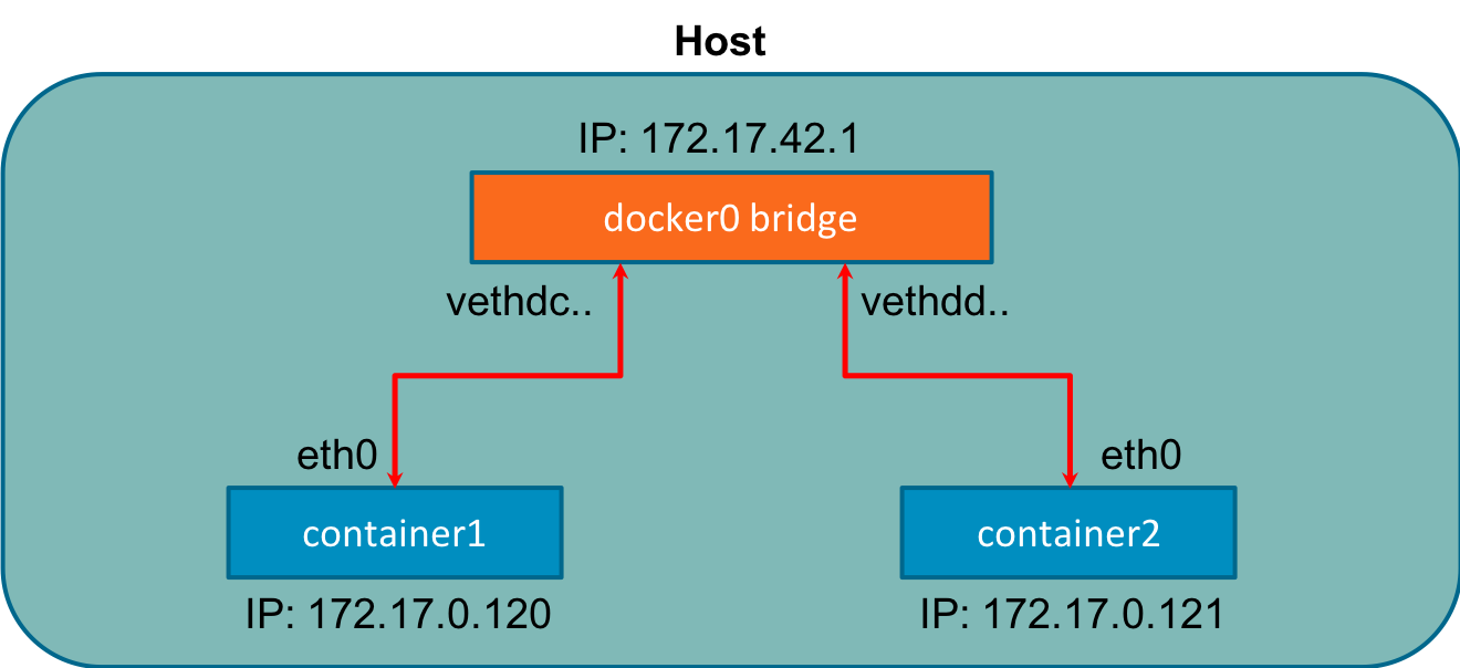
Figure 3-9. Docker Bridge
The CNM maps the network modes to drives we have already discussed. Here is a list of the networking Mode and the Docker engine equivalent.
-
Bridge - Default Docker Bridge (Figure 3-9, and our previous examples show this)
-
Custom or Remote - User Defined Bridge, or allows users to create or use their plugin
-
Overlay - Overlay
-
Null - No networking options
Bridge networks are for containers running on the same host. Communicating with containers running on different hosts can use an overlay network. Docker uses the concept of local and global drivers. Local drivers, bridge, for example, are host-centric and do not do cross-node coordination. That is the job of Global drivers such as Overlay. Global drivers rely on libkv, a key-value store abstraction, to coordinate across machines. The CNM does not provide the key-value store, so external ones like consul, etcd & zookeeper are needed.
In our next section will discuss in depth the technologies enabling Overlay networks.
Overlay Networking
Thus far, our examples have been on a single host, but production applications at scale do not run on a single host. For applications running in containers on separate nodes to communicate, several issues need to be solved. How to coordinate routing information between hosts, port conflicts, ip address management, to name a few. One technology that helps with routing between hosts for containers is Virtual Extensible Local Area Network, VXLAN. In In Figure 3-10, we can see a Layer 2 Overlay network created with VXLAN running over the physical L3 network hence the name overlay.
We briefly discussed VXLAN in Chapter 1, but a more in-depth explanation of how the data transfer works to enable the container to container communication is warranted here.
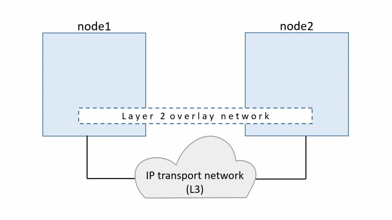
Figure 3-10. VXLAN Tunnel
VXLAN is an extension of the VLAN protocol creating 16 million unique identifiers. Under IEEE 802.1Q, the maximum number of VLANs on a given Ethernet network is 4,094. The transport protocol over a physical data center network is IP plus UDP. VXLAN defines a MAC-in-UDP encapsulation scheme where the original Layer 2 frame has a VXLAN header added wrapped in a UDP IP packet. Figure 3-11 shows the IP packet encapsulated in the UDP packet and its headers.
VXLAN packet is a MAC-in-UDP encapsulated packet. The Layer 2 frame has a VXLAN header added to it and is placed in a UDP-IP packet. The VXLAN identifier is 24 bits. That is how VXLAN can support 16 million segments.
Figure 3-11 is a more detailed version of Chapter 1. We have the VXLAN tunnel endpoints, VTEP’s, on both hosts, attached to the hosts’ bridge interfaces with the containers attached to the bridge. The VTEP performs data frame encapsulation and decapsulation. The VTEP peer interaction ensures that the data gets forwarded to the relevant destination container addresses. The data leaving the containers is encapsulated with VXLAN information and transferred over the VXLAN tunnels to de-encapsulated by the peer VTEP.

Figure 3-11. VXLAN Tunnel Detailed
Overlay networking enables across host communication on the network for containers. The CNM still has other issues that made it incompatible with Kubernetes. The Kubernetes maintainers decided to use the Container Network Interface project started at CoreOS. It is simpler than CNM, does not require daemons, and is designed to be cross-platform.
Container Network Interface
Container Network Interface, CNI, is the software interface that is the interface between the container runtime and the network implementation. There are many options to choose from when implementing a CNI; we will discuss a few notable ones. CNI Started at CoreOS as part of the Rkt project; it is now a Cloud Native Compute Foundation,CNCF ,project. The CNI project consists of a specification and libraries for developing plugins to configure network interfaces in Linux containers. CNI is concerned with containers’ network connectivity by allocating resources when the container gets created and removing them when deleted. A CNI plugin is responsible for associating a network interface to the container network namespace and making any necessary changes to the host. It then assigns the IP to the interface and sets up the routes for it. Figure 3-12 outlines CNI architecture. The Container runtime uses a configuration file for the host’s network information; in Kubernetes, the kubelet also uses this configuration file. The CNI and Container runtime communicate with each other and apply commands to the configured CNI plugin.
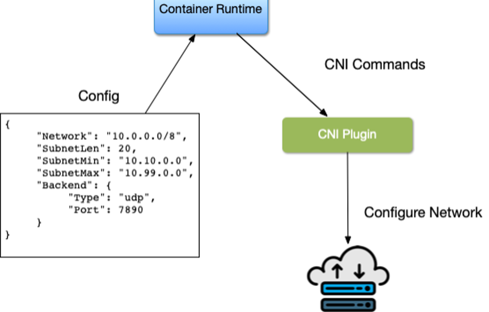
Figure 3-12. Container Network Interface Architecture
There are several opensource projects the implement CNI plugins with various features and functionality. Here is an outline of several.
Cilium is open source software for securing network connectivity between application containers. Cilium is L7/HTTP aware CNI and can enforce network policies on L3-L7 using an identity-based security model decoupled from network addressing. A Linux Technology eBPF powers it.
Flannel is a simple way to configure a layer three network fabric designed for Kubernetes. Flannel focuses on networking. Flannel uses the Kubernetes cluster’s existing etcd datastore to store its state information to avoid providing a dedicated one.
According to Calico, “It combines flexible networking capabilities with run-anywhere security enforcement to provide a solution with native Linux kernel performance and true cloud-native scalability.” It has Full Network policy support and works well in conjunction with other CNI’s. Calico does not use an overlay network. Instead, Calico configures a layer three network that uses the BGP routing protocol to route packets between hosts. Calico can also integrate with Istio, a service mesh, to interpret and enforce policy for workloads within the cluster, both at the service mesh and network infrastructure layers.
AWS has its open-source implementation of a CNI, the AWS VPC CNI. It provides high throughput and availability by being directly on the AWS Network. There is low latency using this CNI by providing little overhead because of no additional overlay network and minimal network jitter running on the AWS Network. Cluster and Network Administrators can apply existing AWS VPC networking and security best practices for building Kubernetes networks on AWS. They can accomplish those best practices because the AWS CNI includes the capability to use native AWS services like VPC flow logs for analyzing network events and patterns, VPC routing policies for traffic management, and Security groups and network access control lists for network traffic isolation. We will discuss more of the AWS VPC CNI later in the book in the Kubernetes and Cloud network chapter.
Note
The Kubernetes.io websites offer a list of more CNI options available. https://kubernetes.io/docs/concepts/cluster-administration/networking/
There are many more options for a CNI, and it is up to the Cluster administrator, Network admins, and the application developers to best decide which CNI solves their business use cases. In later chapters will walk through use cases and deploy several to help admins make a decision.
In our next section, we will walk through container connectivity examples using the golang web server and docker.
Container connectivity
Like we experimented with in the last chapter, we will use the Go minimal webserver to walk through container connectivity. We will explain what is happening at the container level when we deploy the webserver as a container on our Ubuntu host.
The two networking scenarios we will walk through are:
-
Container to Container on the Docker host
-
Container to Container on Separate Hosts
The golang webserver is hard coded to run on port 8080,http.ListenAndServe("0.0.0.0:8080", nil), as we can see in
Example 3-7.
Example 3-7. Minimal web server in Go
packagemainimport("fmt""net/http")funchello(whttp.ResponseWriter,_*http.Request){fmt.Fprintf(w,"Hello")}funcmain(){http.HandleFunc("/",hello)http.ListenAndServe("0.0.0.0:8080",nil)}
To provision our minimal golang web server, we need to create it from a dockerfile. Example 3-8 displays our golang
webserver’s dockerfile. The dockerfile is instructions to specify what to do when building the image. It begins with
the FROM instruction and specifies what the base image should be. RUN instruction specifies a command to execute
Comments start with #. Remember, each line in a Dockerfile creates a new layer if it changes the image’s state.
Developers need to find the right balance between having lots of layers created for the image and the readability of
the Dockerfile.
Example 3-8. Dockerfile for Golang Minimal Webserver
FROMgolang:1.15 AS builderWORKDIR/optCOPYweb-server.go.RUNCGO_ENABLED=0GOOS=linuxgobuild-oweb-server.FROMgolang:1.15WORKDIR/optCOPY--from=0/opt/web-server.CMD["/opt/web-server"]
Since our web server is written in golang, we can compile our go server in a container to reduce the image’s size to only the compiled go binary. We start by using the golang base image with version 1.15 for our webserver.
The
WORKDIRsets the working directory for all the subsequent commands form which to run.COPYcopies the web-server.go file defining our application into the working directing.RUNinstructs docker to compile our golang application in the builder container.
Now we to run our application, we define the
FROMfor the application base image, again being golang:1.15, we can further minimize by possible using other minimal images like alpine.
Being a new container, we again set the working directory to /opt.

COPYhere will copy the compiled go binary from the builder container into the application container.
CMDinstructs docker that the command to run our application is to start our web server.
There are some Dockerfile best practices that developers and admins should adhere to when containerizing their applications.
-
One ENTRYPOINT per Dockerfile, the ENTRYPOINT, or CMD tells Docker what process starts inside the running container, so there should only be one running process; containers are all about process isolation.
-
To cut down on the container layers, developers should combine similar commands into one using “& &” and “.” Each new command in the dockerfile adds a layer to the Docker container image, thus increasing its storage.
-
Use the caching system to improve the containers’ build times. If there is no change to a layer, it should be at the top of the dockerfile. Caching is part of the reason that the order of statements is essential. Add files that are least likely to change first and the ones most likely to change last.
-
Use Multi-stage builds to reduce the size of the final image drastically.
-
Do not install unnecessary tools or packages. Doing this will reduce the containers’ attack surface and size, reducing network transfer times from the registry to the hosts running the containers.
Let us build our golang webserver and review the docker commands to do so.
docker build instructs Docker to build our images from the Dockerfile instructions.
vagrant@ubuntu-xenial:~/advanced_networking_code_examples$ sudo docker build .
Sending build context to Docker daemon   4.27MB
Step 1/8 : FROM golang:1.15 AS builder
1.15: Pulling from library/golang
57df1a1f1ad8: Pull complete
71e126169501: Pull complete
1af28a55c3f3: Pull complete
03f1c9932170: Pull complete
f4773b341423: Pull complete
fb320882041b: Pull complete
24b0ad6f9416: Pull complete
Digest: sha256:da7ff43658854148b401f24075c0aa390e3b52187ab67cab0043f2b15e754a68
Status: Downloaded newer image for golang:1.15
 ---> 05c8f6d2538a
Step 2/8 : WORKDIR /opt
 ---> Running in 20c103431e6d
Removing intermediate container 20c103431e6d
 ---> 74ba65cfdf74
Step 3/8 : COPY web-server.go .
 ---> 7a36ec66be52
Step 4/8 : RUN CGO_ENABLED=0 GOOS=linux go build -o web-server .
 ---> Running in 5ea1c0a85422
Removing intermediate container 5ea1c0a85422
 ---> b508120db6ba
Step 5/8 : FROM golang:1.15
 ---> 05c8f6d2538a
Step 6/8 : WORKDIR /opt
 ---> Using cache
 ---> 74ba65cfdf74
Step 7/8 : COPY --from=0 /opt/web-server .
 ---> dde6002760cd
Step 8/8 : CMD ["/opt/web-server"]
 ---> Running in 2bcb7c8f5681
Removing intermediate container 2bcb7c8f5681
 ---> 72fd05de6f73
Successfully built 72fd05de6f73
The golang minimal webserver for our testing has the container id 72fd05de6f73, which is not friendly to read, so
we can use the docker tag command to give it a friendly name.
vagrant@ubuntu-xenial:~/advanced_networking_code_examples$ sudo docker tag 72fd05de6f73 go-web:v0.0.1
docker images returns the list of locally available images to run. We have one from the test on the docker install and
the busybox we have been using to test our networking setup. If a container is not available locally, it is downloaded
from the registry; network load times impact this, so we need to have as small an image
as possible.
vagrant@ubuntu-xenial:~/advanced_networking_code_examples$sudo docker images REPOSITORY TAG IMAGE ID CREATED SIZE <none> <none> b508120db6ba About a minute ago 857MB go-web v0.0.1 72fd05de6f73 About a minute ago 845MB golang 1.15 05c8f6d2538a2weeks ago 839MB busybox latest 6858809bf6693weeks ago 1.23MB hello-world latest bf756fb1ae659months ago 13.3kB
docker ps shows us the running containers on the host. From our network namespace example, we have one running
busybox container still.
vagrant@ubuntu-xenial:~/advanced_networking_code_examples$sudo docker ps CONTAINER ID IMAGE COMMAND CREATED STATUS PORTS NAMES 1f3f62ad5e02 busybox"/bin/sh"11minutes ago Up11minutes determined_shamir
docker logs will print out any logs that that container is producing from standard out, currently our busybox image
is not printing anything out for us to see.
vagrant@ubuntu-xenial:~$sudo docker logs 1f3f62ad5e02 vagrant@ubuntu-xenial:~$
docker exec allows dev and admins to execute commands inside the docker container. We did this previously while
investigating the docker networking setups.
vagrant@ubuntu-xenial:~$sudo dockerexec1f3f62ad5e02 ip a 1: lo: <LOOPBACK,UP,LOWER_UP> mtu65536qdisc noqueue qlen 1 link/loopback 00:00:00:00:00:00 brd 00:00:00:00:00:00 inet 127.0.0.1/8 scope host lo valid_lft forever preferred_lft forever 7: eth0@if8: <BROADCAST,MULTICAST,UP,LOWER_UP,M-DOWN> mtu1500qdisc noqueue link/ether 02:42:ac:11:00:02 brd ff:ff:ff:ff:ff:ff inet 172.17.0.2/16 brd 172.17.255.255 scope global eth0 valid_lft forever preferred_lft forever vagrant@ubuntu-xenial:~$
Note
More commands and documentation for the Docker CLI are here https://docs.docker.com/engine/reference/commandline/docker/.
In the last section, we built the golang web server as a container. To test connectivity, we will also employ the dnsutils image used by end-to-end testing for Kubernetes. That image is available from the Kubernetes project here: gcr.io/kubernetes-e2e-test-images/dnsutils:1.3
docker pull image_name - The image name will copy the docker images from the Google container registry to our local
docker file system.
$sudo docker pull gcr.io/kubernetes-e2e-test-images/dnsutils:1.3 1.3: Pulling from kubernetes-e2e-test-images/dnsutils 5a3ea8efae5d: Pullcomplete7b7e943444f2: Pullcomplete59c439aa0fa7: Pullcomplete3702870470ee: PullcompleteDigest: sha256:b31bcf7ef4420ce7108e7fc10b6c00343b21257c945eec94c21598e72a8f2de0 Status: Downloaded newer imageforgcr.io/kubernetes-e2e-test-images/dnsutils:1.3 gcr.io/kubernetes-e2e-test-images/dnsutils:1.3
Now that our golang application can run as a container, we can explore the container networking scenarios.
Container to Container
Our first walk through is the communication between two containers running on the same host. We begin by starting the dnsutils image and getting in a shell.
$sudo docker run -it gcr.io/kubernetes-e2e-test-images/dnsutils:1.3 /bin/sh /#
The default docker network setup gives the dnsutils image connectivity to the Internet.
/# ping google.com -c 4PING google.com(172.217.9.78):56data bytes64bytes from 172.217.9.78:seq=0ttl=114time=39.677 ms64bytes from 172.217.9.78:seq=1ttl=114time=38.180 ms64bytes from 172.217.9.78:seq=2ttl=114time=43.150 ms64bytes from 172.217.9.78:seq=3ttl=114time=38.140 ms --- google.com ping statistics ---4packets transmitted,4packets received, 0% packet loss round-trip min/avg/max=38.140/39.786/43.150 ms /#
The golang webserver starts with the default docker bridge; in a separate ssh connection to our vagrant host we start the golang web server with the following command.
$ sudo docker run -it -d -p 80:8080 go-web:v0.0.1
a568732bc191bb1f5a281e30e34ffdeabc624c59d3684b93167456a9a0902369
The -it options are for interactive processes (such as a shell); we must use -it together in order to allocate a
TTY for the container process. -d, run the container in detached mode; this allows us to continue to use the
terminal and outputs the full docker containers id. The -p probably the essential options in terms of the network;
this one creates the port connections between the host and the containers; our golang web server runs on port 8080 and
exposes that port on port 80 on the host.
docker ps verifies that we now have two containers running, the go-web server container with port 8080 exposed on
the host port 80 and shell running inside our dnsutils container.
vagrant@ubuntu-xenial:~$sudo docker ps CONTAINER ID IMAGE COMMAND CREATED STATUS PORTS NAMES 906fd860f84d go-web:v0.0.1"/opt/web-server"4minutes ago Up4minutes 0.0.0.0:8080->8080/tcp frosty_brown 25ded12445df dnsutils:1.3"/bin/sh"6minutes ago Up6minutes brave_zhukovsky
Let us use the docker inspect command to get the Docker IP address of the golang webserver container.
$sudo docker inspect -f'{{range .NetworkSettings.Networks}}{{.IPAddress}}{{end}}'906fd860f84d 172.17.0.2
On the dnsutils image, we can use the docker network address of the golang webserver 172.17.0.2, and the
container port 8080.
/# wget 172.17.0.2:8080Connecting to 172.17.0.2:8080(172.17.0.2:8080)index.html 100%|*******************************************|50:00:00 ETA /# cat index.htmlHello/#
Each container can reach the other over the docker0 bridge and the container ports because they are on the same docker host and the same network. The docker host has routes to the container’s ip address to reach the container on its ip address and port.
vagrant@ubuntu-xenial:~$curl 172.17.0.2:8080 Hellovagrant@ubuntu-xenial:~$
But not the docker ip address and host port from the docker run command.
vagrant@ubuntu-xenial:~$curl 172.17.0.2:80 curl:(7)Failed to connect to 172.17.0.2 port 80: Connection refused vagrant@ubuntu-xenial:~$curl 172.17.0.2:8080 Hello
Now the reverse, using the loopback interface, we demonstrate that the host can only reach the webserver on the host port expose, 80, not the docker port, 8080.
vagrant@ubuntu-xenial:~$curl 127.0.0.1:8080 curl:(7)Failed to connect to 127.0.0.1 port 8080: Connection refused vagrant@ubuntu-xenial:~$curl 127.0.0.1:80 Hellovagrant@ubuntu-xenial:~$
Now back on the dnsutils, the same is true, the dnsutils image on the docker network, using the docker ip address of the go-web container can only use the docker port, 8080, not the exposed host port 80.
/ # wget 172.17.0.2:8080 -qO-
Hello/ #
/ # wget 172.17.0.2:80 -qO-
wget: can't connect to remote host (172.17.0.2): Connection refused
Now to show it is an entirely separate stack, let us try the dnsutils loopback address and both the docker port, and the exposed host port.
/# wget localhost:80 -qO-wget: can't connect to remote host (127.0.0.1): Connection refused/ # wget localhost:8080 -qO-wget: can't connect to remote host(127.0.0.1): Connection refused
Neither work as expected; the dnsutils image has a separate network stack and does not share the go-web server’s network namespace. Knowing why it does not work is vital in Kubernetes to understand since pods are a collection of containers that share the same network namespace. Now will examine how two containers communicate on two separate hosts.
Container to Container Separate Hosts
Our previous example showed us how a container network runs on a local system, but how can two containers across the network on separate hosts communicate? In this example, we will deploy containers on separate hosts and investigate that and how it differs from being on the same host.
Let us start a second vagrant Ubuntu host, host-2, and ssh into it as we did with our docker host. We can see that our IP Address is different from the docker host running our golang webserver.
vagrant@host-2:~$ifconfig enp0s8 enp0s8 Link encap:Ethernet HWaddr 08:00:27:f9:77:12 inet addr:192.168.1.23 Bcast:192.168.1.255 Mask:255.255.255.0 inet6 addr: fe80::a00:27ff:fef9:7712/64 Scope:Link UP BROADCAST RUNNING MULTICAST MTU:1500 Metric:1 RX packets:65630 errors:0 dropped:0 overruns:0 frame:0 TX packets:2967 errors:0 dropped:0 overruns:0 carrier:0 collisions:0 txqueuelen:1000 RX bytes:96493210(96.4 MB)TX bytes:228989(228.9 KB)
We can access our webserver from the docker host’s IP address, 192.168.1.20, on port 80 exposed in the
docker run command options. The port 80 is exposed on the docker host but not reachable on container port 8080 with
the host IP address.
vagrant@ubuntu-xenial:~$curl 192.168.1.20:80 Hellovagrant@ubuntu-xenial:~$vagrant@host-2:~$curl 192.168.1.20:8080 curl:(7)Failed to connect to 192.168.1.20 port 8080: Connection refused vagrant@ubuntu-xenial:~$
The same is true if host-2 tries to reach the container on the containers ip address, using either the docker port, or the host port. Remember docker uses the private address range, 172.17.0.0/16.
vagrant@host-2:~$curl 172.17.0.2:8080 -t 5 curl:(7)Failed to connect to 172.17.0.2 port 8080: No route to host vagrant@host-2:~$curl 172.17.0.2:80 -t 5 curl:(7)Failed to connect to 172.17.0.2 port 80: No route to host vagrant@host-2:~$
For the host to route to the docker ip address, they use an overlay network or some external routing outside Docker. Routing is also external to Kubernetes; many CNI’s help with this issue and are explored when looking at deploy clusters in the Kubernetes Services and the Cloud Services providers chapter.
The previous examples used the docker default network bridge with exposed ports to the hosts. That is how host-2 was able to communicate to the docker container running on the Docker host. This chapter only scratches the surface of container networks. There are many more abstractions to explore, like Ingress and Egress traffic to the entire cluster, Service Discovery, and routing internal and external to the cluster. Later chapters will continue to build on these container networking basics.
Conclusion
In this introduction to container networking, we worked through how containers have evolved to help with Application deployment and advance host efficiency by allowing and segmenting multiple applications on a host. We have walked through the myriad history of containers with the various projects that have come and gone. Containers are powered and managed with namespaces and cgroups, features inside the Linux kernel. We walked through the abstractions that container runtimes maintain for application developers and learned how to deploy them ourselves. Understanding those abstractions are essential to decide what Container Network interface to deploy, their tradeoffs, and benefits. Administrators now have a base understanding of how containers runtimes manage the Linux networking abstractions.
We have completed the basics of container networking! Our knowledge has expanded from using a simple network stack to running different unrelated stacks inside our containers. Knowing about namespaces, how ports are exposed, and communication flow empowers administrators to troubleshoot networking issues quickly and prevent downtime of their applications running in a Kubernetes cluster. How to troubleshoot port issues or test if a port is open on the host, the container, or across the network is a must-have skill for any network engineer and indispensable for devs to troubleshoot their container issues. Kubernetes is built on these basics and abstracts them for developers and in. The next chapter will review how Kubernetes create those abstractions and integrates them into the Kubernetes Networking Model.