This chapter provides a detailed discussion of the different methods for integrating Cisco WAAS into the branch office network infrastructure. It examines both in-path and off-path integration options, applying them to small, medium-sized, and large branch office topologies of various configurations. In-path deployments leverage the inline module available for the WAE appliance models. Off-path deployments in the branch can use WCCP or PBR. The preferred interception method in the branch office environment is WCCP, followed by inline. PBR is limited in the areas of load distribution and failover, and should be considered for interception only as a last resort. Detailed device configurations are provided for each scenario, leveraging current Cisco best practices. This chapter also discusses different deployment scenarios when integrating with Cisco IOS Firewall (IOS FW).
Deploying WAAS in-path means that the WAE is physically placed between two network components, typically a WAN router and LAN switch. Inline deployments are intended for branch office environments, as opposed to the data center. Each WAE supports one 4-port inline network interface card, which allows a single WAE to support interception on two physical paths. The in-path deployment model is typically used in branch office environments where the network topology is less complex than the data center infrastructure. In-path deployments are attractive for branch offices in the following cases:
The WAN access router is unable to sustain the increased traffic throughput enabled by Cisco WAAS. For example, 1 Mbps of compressed traffic from the WAN can decode into tens or hundreds of megabits-per-second worth of uncompressed traffic between the local WAE and clients. Some branch office routers are not suitable for such high levels of throughput. As a general rule, Cisco recommends that branch offices using routers other than the Cisco 1800, 2800, 3700, 3800, and 7200 Series leverage an in-path deployment model.
The IOS routers or switches do not support WCCP or it is not feasible to upgrade the IOS version to a release that is recommended with WCCP. In these cases, an in-path deployment may provide an alternate method for interception that does not require software or configuration changes to the existing branch office network infrastructure.
The IOS router or switches are not under the administrative control of the group deploying WAAS. This is sometimes the case when the network equipment in a branch office is provided and managed by a service provider. In other cases, the team responsible for deploying WAAS might not have administrative access to the network devices, and therefore might not be comfortable depending on another team for operational support of the solution.
In all of these cases, deploying WAAS in-path provides an alternative to off-path deployment models. The following sections describe the in-path integration options for various reference topologies.
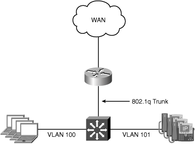
A very basic branch office topology includes a single WAN router and LAN switch. The router is used for connecting the branch office to the WAN and routing traffic between local users and remote resources across the WAN. The site may have multiple VLANs, with the WAN router responsible for routing traffic locally between the VLANs. The reference topology has two existing VLANs, one for data traffic and one for VoIP traffic. This topology will allow demonstration of the per-VLAN interception capabilities of the inline module. Figure 5-1 shows the nonredundant reference branch office topology discussed in this section.
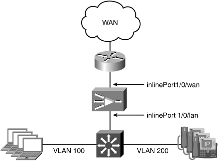
In this scenario, the goal is to optimize traffic from clients on the data VLAN accessing resources at other locations across the WAN. Traffic from the VoIP VLAN should be passed through without optimization. Because an in-path deployment model is being used, a WAE with an inline module installed is physically placed in the network path between the WAN router and the LAN switch. Figure 5-2 shows the branch office topology with a WAE deployed in-path between the WAN router and LAN switch.
The WAN0 port of inlineGroup 1/0 is connected to the LAN interface of the WAN router, and the LAN0 port of inlineGroup 1/0 is connected to a switchport on the LAN switch. No configuration changes are required on the WAN router or LAN switch to accommodate an in-path deployment.
The switchport connecting to the LAN0 port of the WAE inline module should have the PortFast feature enabled. This enables faster recovery of traffic forwarding when the inlineGroup transitions between intercept and bypass operating mode.
Because VLAN 200 is carrying the VoIP traffic, any packets with this VLAN ID are excluded from interception. Packets tagged with VLAN ID 200 will be bridged through the inline module without any optimization. TCP traffic on all other VLANs, including any untagged VLANs, is intercepted and optimized (based on policy configuration). Example 5-1 shows the inlineGroup configuration of the WAE.
Example 5-1. WAE inlineGroup Configuration
!
interface InlineGroup 1/0
 inline vlan all
 no inline vlan 200
 no autosense
 bandwidth 100
 full-duplex
 exit
interface InlineGroup 1/1
 inline vlan all
 shutdown
 exit
!
In Example 5-1, the speed and duplex of the inlineGroup are manually set to 100 Mbps, full-duplex. Note that the speed and duplex configuration settings are applied to the inlineGroup. This ensures that the same interface settings are applied consistently to both ports in the inlineGroup, which is required for proper operation during bypass operating mode.
Example 5-2 shows the full WAE configuration that is used for this deployment scenario.
Example 5-2. Small to Medium-Sized Branch Office In-Path WAE Configuration
!
device mode application-accelerator
!
hostname AUSTIN-WAE
!
ip domain-name cisco.com
!
primary-interface GigabitEthernet 1/0
!
interface GigabitEthernet 1/0
 ip address 10.88.80.137 255.255.255.128
 exit
interface GigabitEthernet 2/0
 shutdown
 exit
!
interface InlineGroup 1/0
 inline vlan all
 no inline vlan 200
 no autosense
 bandwidth 100
 full-duplex
 exit
interface InlineGroup 1/1
 inline vlan all
 shutdown
 exit
!
ip default-gateway 10.88.80.129
!
no auto-register enable

!
ip name-server 10.88.80.53
!
authentication login local enable primary
authentication configuration local enable primary
!
central-manager address cm.cisco.com
cms enable
!
no adapter epm enable
!
<default ATP removed>
!
! End of WAAS configuration
Note that interface GigabitEthernet 1/0 is configured with an IP address and specified as the primary interface. In this example, one of the built-in Ethernet interfaces is used for management traffic to and from the WAE. The default gateway specified in the configuration is used only for traffic sourced from the WAE itself. Alternatively, you can configure an IP address on the inlineGroup interface, which allows you to deploy the WAE without using one of the built-in Ethernet interfaces for management. Example 5-3 shows the inlineGroup configured with a management IP address.
Example 5-3. Management IP Address on inlineGroup
!
primary-interface InlineGroup 1/0
!
interface GigabitEthernet 1/0
 shutdown
 exit
interface GigabitEthernet 2/0
 shutdown
 exit
!
interface InlineGroup 1/0
 ip address 10.88.80.137 255.255.255.128
 inline vlan all
 no inline vlan 200
 no autosense
 bandwidth 100
 full-duplex
 exit
interface InlineGroup 1/1
 inline vlan all
 shutdown
 exit
!
ip default-gateway 10.88.80.129
!
The IP address associated with the inlineGroup is applied to the WAN0 interface. Also note that the primary interface has been configured as inlineGroup 1/0.
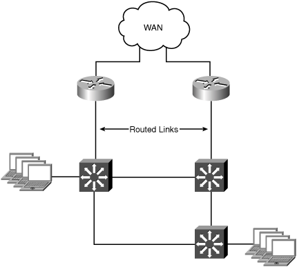
Large branch offices typically have multiple WAN routers and LAN switches for increased capacity and improved availability of the WAN resources. The links between the WAN routers and LAN switches can be configured either as Layer 2 trunks, as in the previous scenario, or as point-to-point routed links. The reference topology is configured with routed links between the WAN routers and LAN switches. The LAN switches handle local routing between VLANs. Figure 5-3 shows the redundant reference branch office topology discussed in this section.
In this scenario, the goal is to optimize traffic from clients accessing resources at other locations across the WAN. Because the links between the WAN routers and LAN switches do not carry all of the VLANs for the site, all TCP traffic will be intercepted and optimized (based on policy configuration).
Traffic can be excluded from optimization by creating a policy in the Application Traffic Policy (ATP) that instructs the WAE to handle certain IP addresses or ranges of IP addresses as pass-through. See Chapter 8, “Configuring WAN Optimization,” for more information on configuring custom traffic policies.
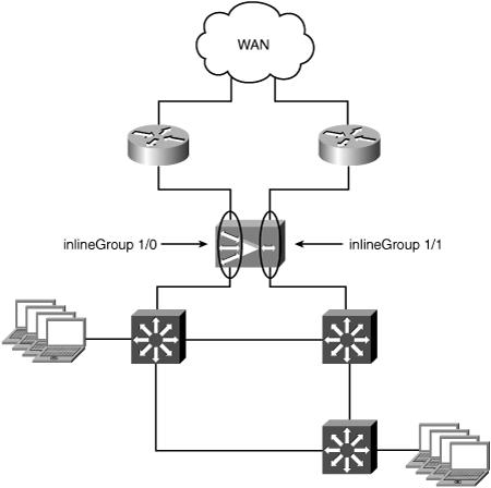
A WAE with an inline module installed is physically placed in the network path between the WAN router and the LAN switch. The in-path deployment model for the redundant reference topology leverages both inline groups in a single module to intercept traffic on two physical paths. Traffic can traverse either inlineGroup when entering or existing the site. Figure 5-4 shows the large redundant branch office topology with a WAE deployed in-path between the WAN routers and LAN switches.
The WAN0 port of each inlineGroup is connected to the LAN interface of one of the WAN routers. The LAN0 port of each inlineGroup is connected to a switchport in the LAN infrastructure. In this reference topology, the LAN port for each inlineGroup is connected to separate switches, but these could just as well be connected to the same switch. Again, there is no special configuration required on the WAN router LAN interfaces or LAN switchports to support the in-path deployment model.
Tip
The switchport connecting to the LAN0 ports of the WAE inline module should have the PortFast feature enabled. This enables faster recovery of traffic forwarding when the inlineGroup transitions between intercept and bypass operating mode.
Example 5-4 shows the inlineGroup configuration of the WAE.
Example 5-4. Redundant Branch Office inlineGroup Configuration
!
interface InlineGroup 1/0
 inline vlan all
 exit
interface InlineGroup 1/1
 inline vlan all
 exit
!
Because this reference topology represents a large branch office, both inline groups are configured with the default setting to autosense the speed and duplex of the individual ports, which allows them to negotiate to 1 Gbps. Example 5-4 also specifies the inline vlan all command, which instructs the WAE to intercept all TCP-based traffic, regardless of the VLAN it is associated with.
Example 5-5 shows the full WAE configuration that is used for this deployment model.
Example 5-5. Redundant Branch Office In-Path WAE Configuration
!
device mode application-accelerator
!
hostname AUSTIN-WAE
!
ip domain-name cisco.com
!
primary-interface GigabitEthernet 1/0
!
interface GigabitEthernet 1/0
 ip address 10.88.80.137 255.255.255.128
 exit
interface GigabitEthernet 2/0
 shutdown
 exit
!
interface InlineGroup 1/0
 inline vlan all
 exit
interface InlineGroup 1/1
 inline vlan all
 exit
!
ip default-gateway 10.88.80.129
!
no auto-register enable
!
ip name-server 10.88.80.53
!
authentication login local enable primary
authentication configuration local enable primary
!
central-manager address cm.cisco.com
cms enable
!
no adapter epm enable
!
<default ATP removed>
!
! End of WAAS configuration
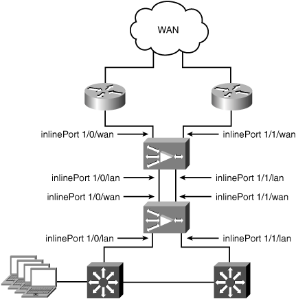
In both the nonredundant and redundant topologies, you can serially connect multiple WAEs in a back-to-back configuration for high availability. Cisco supports clustering up to two WAEs in this fashion. Figure 5-5 shows two WAEs serially clustered for high availability.
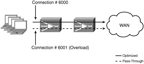
Unlike the off-path integration models discussed later in this chapter, serial clustering does not provide any active/active load sharing across the clustered WAEs. The first WAE in the cluster to receive the TCP SYN packet initiates optimization for that connection. When a peer WAE is discovered across the WAN, the second WAE in the cluster determines through the TFO auto-discovery process that it is in the middle of two other WAEs. This causes the intermediate WAE to handle the connections as pass-through. If one of the WAEs in the cluster becomes overloaded or unavailable, the remaining WAE in the cluster begins optimizing new connections. Existing connections are seen as “In Progress” and handled as pass-through. Figure 5-6 shows the behavior of the clustered WAEs when the first WAE exceeds its maximum optimized connection limit.
Off-path deployments involve leveraging intelligence within the network infrastructure to intercept and redirect traffic to WAAS. With off-path deployments, the WAE is logically inline, as opposed to physically inline as with in-path deployments. Common off-path deployment techniques include WCCP, policy-based routing (PBR), and content switching. This chapter focuses on deployments using WCCP and PBR in the branch office. WCCP is the preferred transparent interception mechanism for off-path deployments. Content switching is discussed as one of the data center network integration options in Chapter 6, “Data Center Network Integration.”
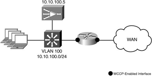
The branch office topology discussed in this section includes a single WAN router and LAN switch. The router is used for connecting the branch office to the WAN and routing traffic between local users and remote resources across the WAN. The WAN router is a software-based platform, such as the Cisco 1800, 2800, or 3800 Series Integrated Services Router (ISR). The site has a single existing VLAN upon which clients are located. Figure 5-7 shows the nonredundant reference branch office topology discussed in this section.
In this scenario, the goal is to optimize traffic from clients accessing resources at other locations across the WAN. For an off-path deployment, the WAE is connected to the network through one of the built-in Ethernet interfaces. WCCP is configured on the WAN router to intercept all TCP traffic and redirect it to the WAE.
Because this topology has only a single existing VLAN, and the link between the WAN access router and the LAN switch is not configured as a trunk, adding a VLAN subnet for the WAE is not desirable. In these cases, the WAE is deployed on the existing VLAN with the hosts it is optimizing connections for. Figure 5-8 shows the branch office topology for this scenario.
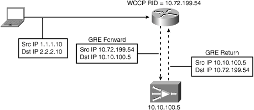
When the WAE is located on the same VLAN with hosts it is optimizing connections for, the router needs some way to differentiate between traffic sourced from a host and traffic coming from the WAE. To accomplish this, the WAE is configured to use WCCP GRE return as the egress method. This causes the WAE to return egress traffic to the intercepting router encapsulated in a WCCP GRE header. The WCCP GRE header uses the WAE IP address as the source IP address and the intercepting router as the destination IP address. By definition of the protocol, WCCP will not intercept GRE-encapsulated traffic sourced from the WAE registered in a service group defined on the router. Figure 5-9 shows the traffic flow between the WAE and intercepting router when WCCP GRE return is configured as the egress method.
The WCCP configuration of the WAN router is shown in Example 5-6.
Example 5-6. Small to Medium-Sized Nonredundant Branch Office WCCP Configuration
!
hostname WR-01
!
ip wccp 61 password cisco
ip wccp 62 password cisco
!
interface FastEthernet0/0
 ip address 10.10.100.1 255.255.255.0
 ip wccp 61 redirect in
!
interface Serial0/0
 description ** Link to WAN **
 ip address 10.72.199.54 255.255.255.252
 ip wccp 62 redirect in
!
Remember that Cisco WAAS uses two WCCP service groups, 61 and 62, for interception on the WAN router. It is important to pay attention to which interfaces you apply each service group. In a branch office, where you have a high concentration of clients, service group 61 is configured on the client-facing interface. In Example 5-6, this is interface FastEthernet0/0. This means that service group 61 will intercept requests coming into the router from clients on interface FastEthernet0/0. Service group 62 is configured on the server-facing interface, in this example Serial0/0. This ensures that service group 62 intercepts responses from the remote servers coming in from the WAN. When there are multiple WAEs deployed at a branch office, this placement of the two service groups causes WCCP to perform load distribution based on the client IP addresses.
The configuration of the WAE in this deployment scenario is shown in Example 5-7.
Example 5-7. Small to Medium-Sized Nonredundant Branch Office WAE Configuration
!
device mode application-accelerator
!
hostname AUSTIN-WAE
!
ip domain-name cisco.com
!
primary-interface GigabitEthernet 1/0
!
interface GigabitEthernet 1/0
 ip address 10.10.100.5 255.255.255.0
 exit
interface GigabitEthernet 2/0
 shutdown
 exit
!
ip default-gateway 10.10.100.1
!
wccp router-list 1 10.10.100.1
wccp tcp-promiscuous router-list-num 1 password cisco
wccp version 2
!
egress-method negotiated-return intercept-method wccp
!
no auto-register enable
!
ip name-server 10.88.80.53
!
authentication login local enable primary
authentication configuration local enable primary
!
central-manager address cm.cisco.com
cms enable
!
no adapter epm enable
!
<default ATP removed>
!
! End of WAAS configuration
When a WAE is deployed on the same VLAN with hosts that it is optimizing connections for, the egress method must be configured for WCCP GRE return. Note the egress-method command in Example 5-7. This tells the WAE to use the return method negotiated via WCCP to handle traffic for connections received using WCCP.
Caution
At the time of this writing, Cisco WAAS only supports WCCP GRE return and IP forwarding as egress methods. If the egress method is configured for negotiated return and the WAE has negotiated L2 return with the intercepting router, the WAE will fall back to IP forwarding as the egress method.
Also note that a default gateway is still configured. The default gateway is used for forwarding traffic sourced from the WAE itself, regardless of the egress method configured.
The Network Module Enhanced WAE (NME-WAE) provides a router-integrated network module capable of running Cisco WAAS. When deploying the NME-WAE, WCCP is required as the interception mechanism. Traffic entering the router is intercepted by WCCP and redirected over an internal GigabitEthernet interface to the NME-WAE. Figure 5-10 shows a remote branch topology using a router-integrated NME-WAE.
The internal GigabitEthernet interface available on the NME-WAE is exposed in the router IOS configuration as an interface named IntegratedServicesEngineslot/port. This interface is configured in a similar manner to any other IOS interface, with the following exceptions:
The IP address of the WAE is configured on the IntegratedServicesEngine interface using the command service-module ip address addr mask.
The default gateway of the WAE is configured on the IntegratedServicesEngine interface using the command service-module ip default-gateway addr.
Example 5-8 shows the full configuration of the IntegratedServicesEngine interface in IOS.
Example 5-8. IOS NME-WAE IOS Interface Configuration
!
interface Integrated-Service-Engine1/0
 ip address 10.88.81.17 255.255.255.240
 ip wccp redirect exclude in
 service-module ip address 10.88.81.18 255.255.255.240
 service-module ip default-gateway 10.88.81.17
 no keepalive
!
Note that the ip wccp redirect exclude in command is configured on the IntegratedServicesEngine interface. This ensures that the WCCP process running on the router does not re-intercept any traffic coming into the router from the NME-WAE. Once the required interface configuration is complete in the router, the WAE can be accessed and managed just like an external WAE appliance. Because the NME-WAE does not have an external console interface for out-of-band management, additional CLI commands are available in IOS for managing the NME-WAE.
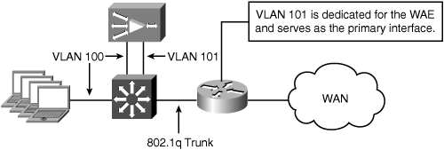
At small to medium-sized sites where an off-path deployment is used with a low-end router, the WAE can be deployed in a two-arm mode to help offload decoded traffic directly to the local client subnet. The two-arm deployment model is intended for small to medium-sized branch offices that have a single host subnet. The two-arm deployment model still leverages WCCP to transparently intercept and redirect traffic to the primary interface of the WAE. The primary interface of the WAE resides on a dedicated subnet, separate from the hosts it is optimizing connections for. The difference with this deployment model is that the second built-in Ethernet interface on the WAE is directly connected to the same subnet as the local hosts. Figure 5-11 shows an example of this topology.
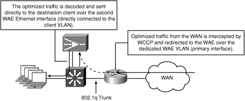
The primary interface of the WAE is used for receiving traffic intercepted using WCCP, and serves as the interface through which the default gateway is configured. The egress method used in this deployment model is IP forwarding. The second WAE interface is configured with an IP address in the local host subnet. This allows optimized traffic that is received across the WAN to be decoded in the WAE and then sent directly to the local destination host systems, bypassing the need to return through the WAN access router. Bypassing the WAN access router reduces the increased levels of throughput that can cause performance problems for legacy routers when WAAS is deployed. Figure 5-12 shows the traffic flow in a two-arm deployment model.
The WCCP configuration of the WAN router is shown in Example 5-9.
Example 5-9. Two-Arm Deployment WAN Router Configuration
!
hostname WR-01
!
ip wccp 61 password cisco
ip wccp 62 password cisco
!
interface FastEthernet0/0
 no ip address
 duplex full
 speed 100
!
interface FastEthernet0/0.201
 description ** Branch Client Subnet **
 encapsulation dot1Q 201
 ip address 10.88.81.17 255.255.255.240
 ip wccp 61 redirect in
!
interface FastEthernet0/0.202
 description ** Branch WAE Subnet **
 encapsulation dot1Q 202
 ip address 10.88.81.1 255.255.255.240
 ip wccp redirect exclude in
!
interface Serial0/0
 description ** Link to WAN **
 ip address 10.88.81.254 255.255.255.252
 ip wccp 62 redirect in
!
Example 5-10 shows the WAE configuration that is used for this deployment model.
Example 5-10. Two-Arm Deployment WAE Configuration
!
device mode application-accelerator
!
hostname AUSTIN-WAE
!
ip domain-name cisco.com
!
primary-interface GigabitEthernet 1/0
!
interface GigabitEthernet 1/0
 ip address 10.88.81.2 255.255.255.240
 exit
interface GigabitEthernet 2/0
 ip address 10.88.81.18 255.255.255.240
 exit
!
ip default-gateway 10.88.81.1
!
wccp router-list 1 10.88.81.1
wccp tcp-promiscuous router-list-num 1 password cisco
wccp version 2
!
no auto-register enable
!
ip name-server 10.88.80.53
!
authentication login local enable primary
authentication configuration local enable primary
!
central-manager address cm.cisco.com
cms enable
!
no adapter epm enable
!
<default ATP removed>
!
! End of WAAS configuration
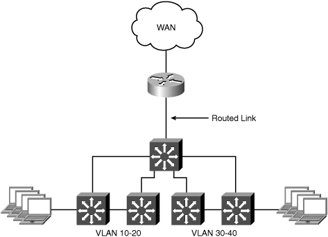
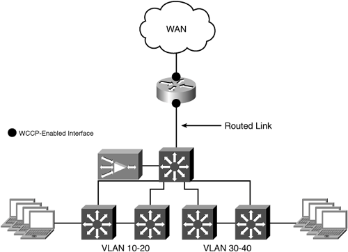
The large nonredundant branch office topology has a similar topology as the small to medium-sized branch. The primary differences are the number of LAN switches and the routing configuration. At larger branch locations, it is also possible for the WAN router to be a hardware-based platform, such as a Cisco 7600 Series router or a Catalyst 6500 Series switch with a FlexWAN module. Large branch offices have clients on multiple VLANs, which are not only accessing resources across the WAN, but are also communicating between each other locally. In these cases, it is most common for the LAN switches to provide IP routing capabilities. Figure 5-13 shows the large nonredundant reference branch office topology discussed in this section.
Here the link between the WAN access router and the LAN switch is a point-to-point routed link. The goal is to optimize traffic from clients going across the WAN. Because there are multiple existing VLANs, and maintaining the proximity of the WAE to the WAN access layer is desired, it makes sense to create a new VLAN on the top-level LAN switch dedicated for the WAE(s) that will be deployed in this branch. WCCP is still configured on the WAN router to intercept all TCP traffic and redirect it to the WAE. Figure 5-14 shows the branch office topology for this deployment model.
Unlike the small to medium-sized topology, the LAN switch performs routing for the subnet the WAE resides on. Because WCCP interception is still configured on the WAN access router, the WAE is multiple Layer 3 hops away from the intercepting router. This scenario requires that WCCP be configured to use both GRE forwarding and GRE return, because the intercepted traffic must traverse an intermediate Layer 3 hop between the intercepting router and the WAE.
The WCCP configuration of the WAN router is shown in Example 5-11.
Example 5-11. Large Nonredundant Deployment WAN Router Configuration
!
hostname WR-01
!
ip wccp 61 password cisco
ip wccp 62 password cisco
!
interface Loopback0
 ip address 10.32.77.66 255.255.255.255
!
interface FastEthernet0/0
 ip address 10.88.80.1 255.255.255.252
 ip wccp 61 redirect in
 duplex full
 speed 100
!
interface Serial0/0
 description ** Link to WAN **
 ip address 10.88.81.254 255.255.255.252
 ip wccp 62 redirect in
!
Example 5-12 shows the configuration of the LAN switch in this deployment scenario.
Example 5-12. Large Nonredundant Deployment LAN Switch Configuration
!
interface GigabitEthernet1/0/1
 ip address 10.88.80.2 255.255.255.252
!
<removed for brevity>
!
interface Vlan196
 ip address 10.88.81.17 255.255.255.240
!
ip route 0.0.0.0 0.0.0.0 10.88.80.1
ip classless
!
end
The configuration of the WAE in this deployment scenario is shown in Example 5-13.
Example 5-13. Large Nonredundant Deployment WAE Configuration
!
device mode application-accelerator
!
hostname AUSTIN-WAE
!
ip domain-name cisco.com
!
primary-interface GigabitEthernet 1/0
!
interface GigabitEthernet 1/0
 ip address 10.88.81.18 255.255.255.128
 exit
interface GigabitEthernet 2/0
 shutdown
 exit
!
ip default-gateway 10.88.81.17
!
wccp router-list 1 10.32.77.66
wccp tcp-promiscuous router-list-num 1 password cisco
wccp version 2
!
egress-method negotiated-return intercept-method wccp
!
no auto-register enable
!
ip name-server 10.88.80.53
!
authentication login local enable primary
authentication configuration local enable primary
!
central-manager address cm.cisco.com
cms enable
!
no adapter epm enable
!
<default ATP removed>
!
! End of WAAS configuration
The default gateway of the WAE is configured as the SVI interface on the LAN switch where the WAE subnet is located. However, because the WAE is multiple Layer 3 hops away from the intercepting router, the IP address configured in the WCCP router list is the Loopback0 interface address on the intercepting router. This is recommended to provide stability to the WCCP process on the intercepting router, and allow for WCCP to continue operating if there are multiple paths available between the WAE and the intercepting router. Another example of this configuration will be provided for the redundant branch office topology.
Another option in this scenario is to move the WCCP interception functionality to the LAN switch. This is useful in cases where you may not have administrative access to the WAN access router or you want to leverage the performance of the LAN switch to perform WCCP interception in hardware. Figure 5-15 shows the branch office topology for this deployment model.
This topology configures WCCP interception on the Cisco Catalyst LAN switch. The LAN switch in this case handles routing for the subnet the WAE resides on. No configuration changes are required on the WAN access router.
The IOS configuration of the LAN switch in this deployment scenario is shown in Example 5-14.
Example 5-14. WCCP on LAN Switch Configuration
!
ip wccp 61 password cisco
ip wccp 62 password cisco
!
interface GigabitEthernet1/0/1
 ip address 10.88.80.2 255.255.255.252
 ip wccp 62 redirect in
!
<removed for brevity>
!
interface Vlan100
 ip address 10.88.81.1 255.255.255.240
 ip wccp 61 redirect in
!
interface Vlan196
 ip address 10.88.81.17 255.255.255.240
!
ip route 0.0.0.0 0.0.0.0 10.88.80.1
ip classless
!
end
WCCP is configured on interface GigabitEthernet1/0/1, which is the physical routed interface connecting to the WAN router at the site. WCCP interception is also enabled on all of the client-facing SVI interfaces.
Caution
Do not use the command ip wccp redirect exclude in on hardware-based (that is, Catalyst) platforms.
Tip
When configuring WCCP on a hardware-based platform, always use inbound redirection to ensure full hardware acceleration.
The configuration of the WAE in this deployment scenario is shown in Example 5-15.
Example 5-15. WCCP on LAN Switch Deployment WAE Configuration
!
device mode application-accelerator
!
hostname AUSTIN-WAE
!
ip domain-name cisco.com
!
primary-interface GigabitEthernet 1/0
!
interface GigabitEthernet 1/0
 ip address 10.88.80.137 255.255.255.128
 exit
interface GigabitEthernet 2/0
 shutdown
 exit
!
ip default-gateway 10.88.81.17
!
wccp router-list 1 10.88.81.17
wccp tcp-promiscuous router-list-num 1 l2-redirect mask-assign password cisco
wccp version 2
!
no auto-register enable
!
ip name-server 10.88.80.53
!
authentication login local enable primary
authentication configuration local enable primary
!
central-manager address cm.cisco.com
cms enable
!
no adapter epm enable
!
<default ATP removed>
!
! End of WAAS configuration
Because WCCP is running on a hardware-based platform in this configuration, there are two additional WCCP options configured on the WAE: l2-redirect and mask-assign. The l2-redirect option tells the Catalyst 3750 to redirect traffic to the WAE by rewriting the destination MAC address of redirected traffic to equal the MAC address of the target WAE (as opposed to encapsulating the packet in a WCCP GRE header). The mask-assign option is an alternative to the default hash assignment, which is optimized for use in hardware-based platforms. Both of these options are required to ensure that WCCP redirection is handled completely in hardware.
Redundant branch office network topologies present additional challenges in that there are multiple paths traffic can traverse within the site and when entering and existing the WAN. It is common for the traffic load from the site to be distributed across multiple WAN links for increased capacity/performance, and to minimize the impact of a single WAN link outage. When deploying WAAS in redundant branch office topologies, one of the design goals is to preserve the original path selection, or outbound load distribution, of traffic across multiple WAN links. The following sections explore various placement and interception configuration options for off-path integration in redundant branch office topologies.
Small/medium redundant branch offices have multiple WAN routers and one or more LAN switches. The site may have multiple VLANs, with the WAN router responsible for routing traffic locally between the VLANs. The reference topology has a single existing VLAN. Figure 5-16 shows the redundant reference branch office topology discussed in this section.
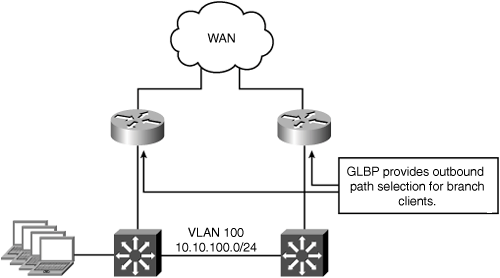
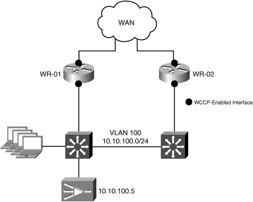
In this scenario, all IP routing for the branch is handled by the WAN routers (that is, the LAN switches function only at Layer 2). The WAN access routers are configured with GLBP on the LAN interfaces to provide default gateway redundancy for the local host systems. Traffic can enter or exit the site through either WAN router. Because there is only a single existing VLAN, and the links between the WAN access routers and the LAN switches are not configured as trunks, adding a dedicated VLAN for the WAE is not desirable. In these cases, the WAE is deployed on the existing VLAN with the hosts it is optimizing connections for. Figure 5-17 shows the branch office topology for this deployment model.
Both WAN access routers are configured with WCCP for transparent interception. Because both WAN access routers are members of the same WCCP service group, traffic can enter or exit the remote office through either router. The deterministic behavior of WCCP will ensure that traffic is redirected to the correct WAE in both directions. Egress traffic from the WAEs is returned directly to the intercepting routers’ real interface IP addresses (as opposed to the GLBP virtual IP addresses) using WCCP GRE return as the egress method. In addition to allowing the WAE to reside on the same VLAN with client systems, this configuration preserves the original WAN router selection for intercepted traffic.
Tip
The use of WCCP GRE return as an egress method is only intended for software-based platforms (ISR, 7200, and so on). If a hardware-based platform is being used as the WAN access routers (in other words, Cisco Catalyst switch), IP forwarding should be used as the egress method.
As traffic is redirected to the WAE, the WAE records the source IP address (from the WCCP GRE header) of the intercepting router that redirected the traffic to it. This allows the WAE to return the traffic to the intercepting router it came from once processing is complete. This stateful behavior is performed on a connection-by-connection basis, and is a key feature that allows for the existing WAN router selection to be preserved. The configuration of the WAN routers is shown in Example 5-16.
Example 5-16. Small to Medium-Sized Redundant Deployment WAN Router Configuration
!
hostname WR-01
!
ip wccp 61 password cisco
ip wccp 62 password cisco
!
interface FastEthernet0/0
 ip address 10.10.100.2 255.255.255.0
 ip wccp 61 redirect in
 speed 100
 full-duplex
 glbp 1 ip 10.10.100.1
 glbp 1 priority 105
 glbp 1 preempt delay minimum 60
 glbp 1 load-balancing host-dependent
 glbp 1 authentication text cisco
!
interface Serial0/0
 description ** Link to WAN **
 ip address 10.88.81.254 255.255.255.252
 ip wccp 62 redirect in
!

!
hostname WR-02
!
ip wccp 61 password cisco
ip wccp 62 password cisco
!
interface FastEthernet0/0
 ip address 10.10.100.3 255.255.255.0
 ip wccp 61 redirect in
 speed 100
 full-duplex
 glbp 1 ip 10.10.100.1
 glbp 1 priority 100
 glbp 1 preempt delay minimum 60
 glbp 1 load-balancing host-dependent
 glbp 1 authentication text cisco

!
interface Serial0/0
 description ** Link to WAN **
 ip address 10.88.81.250 255.255.255.252
 ip wccp 62 redirect in
!
Example 5-17 shows the WAE configuration that is used for this deployment model.
Example 5-17. Small to Medium-Sized Redundant Deployment WAE Configuration
!
device mode application-accelerator
!
hostname AUSTIN-WAE
!
ip domain-name cisco.com
!
primary-interface GigabitEthernet 1/0
!
interface GigabitEthernet 1/0
 ip address 10.10.100.5 255.255.255.0
 exit
interface GigabitEthernet 2/0
 shutdown
 exit
!
ip default-gateway 10.10.100.1
!
wccp router-list 1 10.10.100.2 10.10.100.3
wccp tcp-promiscuous router-list-num 1 password cisco
wccp version 2
!
egress-method negotiated-return intercept-method wccp
!
no auto-register enable
!
ip name-server 10.88.80.53
!
authentication login local enable primary
authentication configuration local enable primary
!
central-manager address cm.cisco.com
cms enable
!
no adapter epm enable
!
<default ATP removed>
!
! End of WAAS configuration
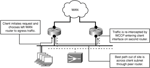
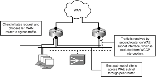
It is important to analyze the current routing configuration and traffic flows at sites with redundant topologies. It is possible even when deploying the WAEs on a dedicated subnet to experience a redirection loop for traffic that transits between routers on host subnets. Figure 5-18 shows an example of how a redirection loop can be created when traffic passes between WAN access routers on host VLANs.
The solution is to prevent traffic from transiting between routers over the existing host subnets, and make the newly created WAE subnet the transit path between the WAN access routers. If the host subnets are not a transit path between the WAN access routers, it is possible to deploy the WAEs on an existing host subnet. If any of the current host subnets are serving as transit paths between the WAN access routers, the WAEs should be deployed on a dedicated subnet that can also serve as the new transit path. Figure 5-19 shows the modified traffic flow with the WAE subnet serving as the transit path between the WAN access routers.
Example 5-18 shows the configuration of the WAN routers.
Example 5-18. Small to Medium-Sized Redundant Deployment WAN Router Configuration
!
hostname WR-01
!
ip wccp 61 password cisco
ip wccp 62 password cisco
!
interface FastEthernet0/0
 no ip address
 duplex full
 speed 100
!
interface FastEthernet0/0.201
 ip address 10.10.100.2 255.255.255.0
 ip wccp 61 redirect in
 speed 100
 full-duplex
 glbp 1 ip 10.10.100.1
 glbp 1 priority 105
 glbp 1 preempt delay minimum 60
 glbp 1 load-balancing host-dependent
 glbp 1 authentication text cisco
!
interface FastEthernet0/0.202
 ip address 10.88.81.2 255.255.255.240
 ip wccp redirect exclude in
 speed 100
 full-duplex
 glbp 2 ip 10.88.81.1
 glbp 2 priority 105
 glbp 2 preempt delay minimum 60
 glbp 2 load-balancing host-dependent
 glbp 2 authentication text cisco

!
interface Serial0/0
 description ** Link to WAN **
 ip address 10.88.81.254 255.255.255.252
 ip wccp 62 redirect in
!
router ospf 100
 passive-interface FastEthernet0/0.201
 network 10.10.100.0 0.0.0.255 area 0
 network 10.88.81.0 0.0.0.15 area 0
 network 10.88.81.252 0.0.0.3 area 0
!
_________________________________________
!
hostname WR-02
!
ip wccp 61 password cisco
ip wccp 62 password cisco
!
interface FastEthernet0/0
 no ip address
 duplex full
 speed 100
!
interface FastEthernet0/0.201
 ip address 10.10.100.3 255.255.255.0
 ip wccp 61 redirect in
 speed 100
 full-duplex
 glbp 1 ip 10.10.100.1
 glbp 1 priority 100
 glbp 1 preempt delay minimum 60
 glbp 1 load-balancing host-dependent
 glbp 1 authentication text cisco
!
interface FastEthernet0/0.202
 ip address 10.88.81.3 255.255.255.240
 ip wccp redirect exclude in
 speed 100
 full-duplex
 glbp 2 ip 10.88.81.1
 glbp 2 priority 100
 glbp 2 preempt delay minimum 60
 glbp 2 load-balancing host-dependent
 glbp 2 authentication text cisco

!
interface Serial0/0
 description ** Link to WAN **
 ip address 10.88.81.250 255.255.255.252
 ip wccp 62 redirect in
!
router ospf 100
 passive-interface FastEthernet0/0.201
 network 10.10.100.0 0.0.0.255 area 0
 network 10.88.81.0 0.0.0.15 area 0
 network 10.88.81.248 0.0.0.3 area 0
!
In Example 5-18, the interface connecting to the client subnet is set as passive under the OSPF process. This prevents a routing protocol adjacency from forming across the client subnet, which prevents it from becoming a transit path.
Note
Make sure that any static routes that are configured with a next-hop address across a client subnet are changed to use the WAE subnet as the transit path.
Example 5-19 shows the WAE configuration that is used for this deployment model.
Example 5-19. Dedicated WAE Subnet WAE Configuration
!
device mode application-accelerator
!
hostname AUSTIN-WAE
!
ip domain-name cisco.com
!
primary-interface GigabitEthernet 1/0
!
interface GigabitEthernet 1/0
 ip address 10.88.81.5 255.255.255.240
 exit
interface GigabitEthernet 2/0
 shutdown
 exit
!
ip default-gateway 10.88.81.1

!
wccp router-list 1 10.88.81.2 10.88.81.3
wccp tcp-promiscuous router-list-num 1 password cisco
wccp version 2
!
egress-method negotiated-return intercept-method wccp
!
no auto-register enable
!
ip name-server 10.88.80.53
!
authentication login local enable primary
authentication configuration local enable primary
!
central-manager address cm.cisco.com
cms enable
!
no adapter epm enable
!
<default ATP removed>
!
! End of WAAS configuration
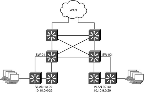
Large branch offices are much more likely to implement a multilayer Core, Distribution, and Access topology. It is also common for the WAN routers at large branch offices to be hardware-based platforms, such as Catalyst 6500 Series switches or 7600 Series routers. With a more extensive network infrastructure in large branch offices comes more options for where to configure interception. Figure 5-20 shows the large redundant reference branch office topology discussed in this section.
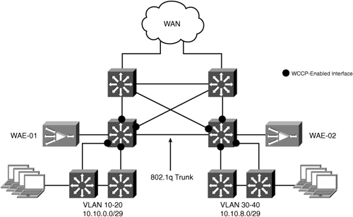
All of the switch links in the reference topology are routed links. Traffic load is distributed across both WAN routers as it leaves the site. We want to preserve this routing behavior after WAAS is deployed. Although we want to maintain the proximity of the WAEs to the WAN access layer, we need to consider how egress traffic from the WAEs will be handled. Because this topology uses hardware-based WAN routers, using WCCP GRE return as the egress method is not recommended. Instead, configure WCCP one hop away from the WAN routers on the LAN distribution switches. By moving down into the branch office infrastructure, we can take advantage of the dynamic IGP routing between the WAN routers and the LAN distribution layer switches. With the WAEs using IP forwarding as the egress method, and the LAN distribution switches configured as the default gateway of the WAEs, the routing protocol can handle outbound load distribution to the WAN routers. Figure 5-21 shows the branch office topology for this deployment model.
A dedicated VLAN is created for the WAEs on the LAN distribution switches. To facilitate WCCP L2 forwarding, the WAE VLAN is trunked between the two LAN distribution switches. This allows traffic to be intercepted on either LAN distribution switch and get redirected to the correct WAE. HSRP is configured on the WAE VLAN to provide default gateway redundancy.
The IOS configuration of both LAN distribution switches is shown in Example 5-20.
Example 5-20. Large Redundant Off-Path Deployment LAN Switch Configuration
!
hostname SW-01
!
ip wccp 61 redirect-list NO-LOCAL-TRAFFIC password cisco
ip wccp 62 redirect-list NO-LOCAL-TRAFFIC password cisco
!
interface Port-channel1
 switchport
 switchport trunk encapsulation dot1q
 switchport trunk allowed vlan 10-40,100
 switchport mode trunk
 no ip address
!
interface GigabitEthernet1/0
 description ** Link to WAN Router **
 ip address 10.88.81.250 255.255.255.252
 ip wccp 62 redirect in
!
interface GigabitEthernet1/1
 description ** Link to LAN Access Switch **
 ip address 10.88.81.246 255.255.255.252
 ip wccp 61 redirect in
!
interface GigabitEthernet1/2
 switchport
 switchport trunk encapsulation dot1q
 switchport trunk allowed vlan 10-40,100
 switchport mode trunk
 no ip address
 channel-group 1 mode desirable
!
interface GigabitEthernet1/3
 description ** WAE-01 **
 switchport
 switchport access vlan 100
 switchport mode access
 no ip address
 spanning-tree portfast
!
interface GigabitEthernet2/0
 description ** Link to WAN Router **
 ip address 10.88.81.254 255.255.255.252
 ip wccp 62 redirect in
!
interface GigabitEthernet2/1
 description ** Link to LAN Access Switch **
 ip address 10.88.81.242 255.255.255.252
 ip wccp 61 redirect in
!
interface GigabitEthernet2/2
 switchport
 switchport trunk encapsulation dot1q
 switchport trunk allowed vlan 10-40,100
 switchport mode trunk
 no ip address
 channel-group 1 mode desirable
!
<removed for brevity>
!
interface Vlan100
 description ** WAAS WAE VLAN **
 ip address 10.88.81.2 255.255.255.240
 standby 1 ip 10.88.81.1
 standby 1 priority 105
 standby 1 password cisco
!
ip access-list extended NO-LOCAL-TRAFFIC
 deny ip 10.10.0.0 0.0.15.255 10.10.0.0 0.0.15.255
 permit ip any any
!
end
________________________________________________________
!
hostname SW-02
!
ip wccp 61 redirect-list NO-LOCAL-TRAFFIC password cisco
ip wccp 62 redirect-list NO-LOCAL-TRAFFIC password cisco
!
interface Port-channel1
 switchport
 switchport trunk encapsulation dot1q
 switchport trunk allowed vlan 10-40,100
 switchport mode trunk
 no ip address
!
interface GigabitEthernet1/0
 description ** Link to WAN Router **
 ip address 10.88.81.238 255.255.255.252
 ip wccp 62 redirect in
!
interface GigabitEthernet1/1
 description ** Link to LAN Access Switch **
 ip address 10.88.81.234 255.255.255.252
 ip wccp 61 redirect in
!
interface GigabitEthernet1/2
 switchport
 switchport trunk encapsulation dot1q
 switchport trunk allowed vlan 10-40,100
 switchport mode trunk
 no ip address
 channel-group 1 mode desirable
!
interface GigabitEthernet1/3
 description ** WAE-02 **
 switchport
 switchport access vlan 100
 switchport mode access
 no ip address
 spanning-tree portfast
!
interface GigabitEthernet2/0
 description ** Link to WAN Router **
 ip address 10.88.81.230 255.255.255.252
 ip wccp 62 redirect in
!
interface GigabitEthernet2/1
 description ** Link to LAN Access Switch **
 ip address 10.88.81.226 255.255.255.252
 ip wccp 61 redirect in
!
interface GigabitEthernet2/2
 switchport
 switchport trunk encapsulation dot1q
 switchport trunk allowed vlan 10-40,100
 switchport mode trunk
 no ip address
 channel-group 1 mode desirable
!
<removed for brevity>
!
interface Vlan100
 description ** WAAS WAE VLAN **
 ip address 10.88.81.3 255.255.255.240
 standby 1 ip 10.88.81.1
 standby 1 priority 100
 standby 1 password cisco
!
ip access-list extended NO-LOCAL-TRAFFIC
 deny ip 10.10.0.0 0.0.15.255 10.10.0.0 0.0.15.255
 permit ip any any
!
end
The configuration of the WAEs in this deployment scenario is shown in Example 5-21.
Example 5-21. Large Redundant Off-Path Deployment WAE Configuration
!
device mode application-accelerator
!
hostname WAE-01
!
ip domain-name cisco.com
!
primary-interface GigabitEthernet 1/0
!
interface GigabitEthernet 1/0
 ip address 10.88.81.5 255.255.255.240
 exit
interface GigabitEthernet 2/0
 shutdown
 exit
!
ip default-gateway 10.88.81.1
!
wccp router-list 1 10.88.81.2 10.88.81.3
wccp tcp-promiscuous router-list-num 1 l2-redirect mask-assign password cisco
wccp version 2
!
no auto-register enable
!
ip name-server 10.88.80.53
!
authentication login local enable primary
authentication configuration local enable primary
!
central-manager address cm.cisco.com
cms enable
!
no adapter epm enable
!
<default ATP removed>
!
! End of WAAS configuration
Both WAE configurations are the same, except for the WAE IP address itself. Because WCCP is running on a hardware-based platform in this configuration, there are two additional WCCP options configured on the WAE: l2-redirect and mask-assign. The l2-redirect option tells the Catalyst 3750 to redirect traffic to the WAE by rewriting the destination MAC address of redirected traffic to equal the MAC address of the target WAE (as opposed to encapsulating the packet in a WCCP GRE header). The mask-assign option is an alternative to the default hash assignment, which is optimized for use in hardware-based platforms. Both of these options are required to ensure that WCCP redirection is handled completely in hardware. The default gateway of the WAE is configured as the HSRP VIP. In the WCCP router list, the IP address of the directly connected WAE VLAN interface is configured.
Inbound WCCP interception is configured on the interfaces connecting to the WAN routers and the interfaces connecting to the LAN access switches.
Caution
Do not use the command ip wccp redirect exclude in on hardware-based (that is, Catalyst) platforms.
Tip
When configuring WCCP on a hardware-based platform, always use inbound redirection to ensure full hardware acceleration.
As an alternative to a single HSRP virtual IP (VIP) address that the WAEs use a default gateway, Multigroup HSRP (MHSRP) can be configured on the WAE VLAN. With this configuration, each WAE can use a different VIP for its default gateway, which accomplishes a manual form of load distribution. Example 5-22 shows an MHSRP configuration on the WAE VLAN interface configuration on the LAN distribution switches.
Example 5-22. MHSRP Configuration for WAE VLAN
!
hostname SW-01
!
interface Vlan100
 description ** WAAS WAE VLAN **
 ip address 10.88.81.3 255.255.255.240
 standby 1 ip 10.88.81.1
 standby 1 priority 105
 standby 1 password cisco
 standby 2 ip 10.88.81.2
 standby 2 priority 105
 standby 2 password cisco
!
______________________________________
!
hostname SW-02
!
interface Vlan100
 description ** WAAS WAE VLAN **
 ip address 10.88.81.4 255.255.255.240
 standby 1 ip 10.88.81.1
 standby 1 priority 100
 standby 1 password cisco
 standby 2 ip 10.88.81.2
 standby 2 priority 100
 standby 2 password cisco
!
Example 5-23 shows the configurations of the WAEs in this deployment scenario.
Example 5-23. WAE Configuration Using MHSRP
!
device mode application-accelerator
!
hostname WAE-01
!
ip domain-name cisco.com
!
primary-interface GigabitEthernet 1/0
!
interface GigabitEthernet 1/0
 ip address 10.88.81.5 255.255.255.240
 exit
interface GigabitEthernet 2/0
 shutdown
 exit
!
ip default-gateway 10.88.81.1
!
wccp router-list 1 10.88.81.3 10.88.81.4
wccp tcp-promiscuous router-list-num 1 l2-redirect mask-assign password cisco
wccp version 2
!
no auto-register enable
!
ip name-server 10.88.80.53
!
authentication login local enable primary
authentication configuration local enable primary
!
central-manager address cm.cisco.com
cms enable
!
no adapter epm enable
!
<default ATP removed>
!
! End of WAAS configuration
______________________________________________________________________________
!
device mode application-accelerator
!
hostname WAE-02
!
ip domain-name cisco.com
!
primary-interface GigabitEthernet 1/0
!
interface GigabitEthernet 1/0
 ip address 10.88.81.6 255.255.255.240
 exit
interface GigabitEthernet 2/0
 shutdown
 exit
!
ip default-gateway 10.88.81.2
!
wccp router-list 1 10.88.81.3 10.88.81.4
wccp tcp-promiscuous router-list-num 1 l2-redirect mask-assign password cisco
wccp version 2
!
no auto-register enable
!
ip name-server 10.88.80.53
!
authentication login local enable primary
authentication configuration local enable primary
!
central-manager address cm.cisco.com
cms enable
!
no adapter epm enable
!
<default ATP removed>
!
! End of WAAS configuration
Policy-based routing (PBR) is another transparent interception option for off-path deployments. PBR is configured on the same routers and switches where you would normally configure WCCP. You should take into account the following items when considering PBR for transparent interception:
PBR requires more configuration steps in IOS than does WCCP.
The only egress method supported with PBR is IP forwarding. This means that the WAEs cannot be deployed multiple L3 hops away from the intercepting routers.
By default, PBR does not provide load distribution among multiple WAEs at a site.
By default, PBR does not track the availability of the WAE to receive traffic (requires the IOS IP SLA feature).
Based on these limitations, PBR is recommended over WCCP only as a last resort. The remainder of this section provides sample configurations for using PBR for transparent interception with WAAS.
The following example shows the configuration steps required to use PBR for WAAS interception:
Configure an access list to match the traffic you want to redirect to WAAS:
!
access-list 100 permit tcp any any
access-list 100 deny ip any any
!
Create a route map that references the access list, and sets a next-hop IP address of the WAE:
!
route-map WAAS permit 10
     match ip address 100
     set ip next-hop 10.88.81.2
!
Apply PBR to the individual interfaces:
!
interface FastEthernet0/0
 no ip address
 duplex full
 speed 100
!
interface FastEthernet0/0.201
 description ** Branch Client Subnet **
 encapsulation dot1Q 201
 ip address 10.88.81.17 255.255.255.240
 ip policy route-map WAAS
!
interface FastEthernet0/0.202
 description ** Branch WAE Subnet **
 encapsulation dot1Q 202
 ip address 10.88.81.1 255.255.255.240
!
interface Serial0/0
 description ** Link to WAN **
 ip address 10.88.81.254 255.255.255.252
 ip policy route-map WAAS
By default, PBR does not verify that the IP next-hop address specified in the route map is reachable. This can lead to a situation where traffic is being redirected to a WAE that is down. You can configure IOS devices to check the availability of IP next-hop address(es) using a combination of IP SLA features and the set ip next-hop verify-availability route map command.
Example 5-24 shows how to configure the WAN router to verify that the IP next-hop address specified in the route map is up and reachable.
Example 5-24. Verifying IP Next Hop Address Using IP SLA
!
hostname WR-01
!
ip sla monitor 10
 type echo protocol ipIcmpEcho 10.88.81.2
 frequency 10
ip sla monitor schedule 10 life forever start-time now
!
track 10 rtr 10 reachability
!
route-map WAAS permit 10
 match ip address 100
 set ip next-hop verify-availability 10.88.81.2 10 track 10
!
If the IP next-hop address becomes unavailable, the WAN router will start forwarding traffic natively across the WAN using the entries in the routing table as opposed to the policy route.
Another limitation of PBR is scenarios where multiple WAEs are deployed at a single site. Multiple WAEs can be deployed at a single site for scalability, redundancy, or both. The route map command set ip next-hop allows you to define multiple IP addresses. Example 5-25 shows a router-map with multiple next-hop addresses configured.
Example 5-25. Multiple IP Next Hop Addresses
!
route-map WAAS permit 10
       match ip address 100
       set ip next-hop 10.88.81.2 10.88.81.3
!
In Example 5-25, the IP addresses of both WAEs are configured as “IP next hop” addresses. The problem with this configuration is that the second IP address, 10.88.81.3, will be used only if the first IP address becomes unavailable. When the failover occurs to the second WAE, all traffic associated with existing TCP connections will be forwarded unoptimized. As new TCP connections are established, they will be optimized. So at any given time, only a single WAE will be receiving traffic. A potential workaround for this would be to use multiple route map entries to manually distribute traffic to each WAE. In Example 5-26, the LAN subnet at the location is using IP subnet 10.10.10.0/24. PBR is configured to send even-numbered hosts to the first WAE, and odd-numbered hosts to the second WAE. Each route map entry would be configured with the IP addresses of both WAEs, so if one fails, traffic will be rerouted to the other WAE.
Example 5-26. Traffic Distribution with PBR
!
hostname WR-01
!
ip sla monitor 10
 type echo protocol ipIcmpEcho 10.88.81.2
 frequency 10
ip sla monitor schedule 10 life forever start-time now
ip sla monitor 20
 type echo protocol ipIcmpEcho 10.88.81.3
 frequency 10
ip sla monitor schedule 20 life forever start-time now
!
track 10 rtr 10 reachability
!
track 20 rtr 20 reachability
!
access-list 100 permit tcp 10.10.10.1 0.0.0.254 any
access-list 100 permit tcp any 10.10.10.1 0.0.0.254
access-list 101 permit tcp 10.10.10.0 0.0.0.254 any
access-list 101 permit tcp any 10.10.10.1 0.0.0.254
!
route-map WAAS permit 10
 match ip address 100
 set ip next-hop verify-availability 10.88.81.2 10 track 10
 set ip next-hop verify-availability 10.88.81.3 20 track 20

!
route-map WAAS permit 20
 match ip address 101
 set ip next-hop verify-availability 10.88.81.3 10 track 20
 set ip next-hop verify-availability 10.88.81.2 20 track 10
!
Cisco IOS Firewall (IOS FW) is a fundamental part of the integrated threat-control solution available on Cisco low- and midrange routing platforms. An enhancement in Cisco IOS Release 12.4(11)T2 allows Cisco IOS FW and Cisco IOS IPS to recognize traffic being optimized by Cisco WAAS. With this enhancement, Cisco IOS FW observes the TCP options used in WAAS automatic discovery. If Cisco IOS FW notices that a connection has successfully completed WAAS automatic discovery, it permits the initial sequence number shift for the connection and maintains the Layer 4 state on the optimized connection.
Note
The capability of Cisco WAAS to interoperate with Cisco IOS FW and Cisco IOS IPS applies only to the Cisco IOS Zone-Based Policy Firewall starting from Release 12.4(11)T2. Cisco IOS Classic Firewall does not incorporate the Cisco WAAS interoperability enhancement.
In a branch office deployment, it is common to have security features, such as Cisco IOS FW, Cisco IOS IPS, or IPsec VPN, deployed on an ISR router. Cisco WAAS has three different deployment options:
Cisco WAAS deployed with an NME-WAE on the same router as Cisco IOS FW and IOS IPS, using WCCP redirect for traffic interception: This scenario supports IPsec VPN, along with IOS FW and IOS IPS features.
Cisco WAAS deployed as an off-path, standalone appliance, using WCCP redirection for traffic interception: This scenario also supports IPsec VPN, along with IOS FW and IOS IPS features,. The configuration for this option is the same as for the previous option.
Cisco WAAS deployed as an inline appliance, in front of the ISR router: This scenario supports IPsec VPN, along with IOS FW. In this case, because IOS FW and IOS IPS will receive WAAS optimized packets, Layer 7 inspection on the client side is not supported. The IOS IPS feature is partially supported because traffic is uncompressed during the first few RTTs, and IOS IPS will work if a signature is matched at the beginning of a connection.
An edge Cisco WAAS with Cisco IOS FW or Cisco IOS IPS is applied at branch office sites that must inspect traffic moving to and from a WAN connection and may use VPN connectivity. Cisco IOS FW monitors traffic for optimization indicators (TCP options and subsequent TCP sequence number changes) and allows optimized traffic to pass, while still applying Layer 4 stateful inspection and deep packet inspection to all traffic, maintaining security while accommodating Cisco WAAS optimization advantages.
Example 5-27 shows a configuration with IOS FW and WCCP interception configured on the same router.
Example 5-27. IOS Firewall and WCCP Interception
!
ip wccp 61
ip wccp 62
!
ip inspect WAAS enable
class-map type inspect match-any most-traffic
 match protocol icmp
 match protocol ftp
 match protocol tcp
 match protocol udp
!
policy-map type inspect p1
 class type inspect most-traffic
  inspect
 class class-default
zone security inside
zone security outside
zone-pair security in-out source inside destination outside
 service-policy type inspect p1
zone-pair security out-in source outside destination inside
 service-policy type inspect p1
!
interface GigabitEthernet0/0
 description Trusted interface
 ip address 10.70.0.1 255.255.255.0
 ip wccp 61 redirect in
 zone-member security inside
!
interface GigabitEthernet0/1
 description Untrusted interface
 ip address 10.72.2.3 255.255.255.0
 ip wccp 62 redirect in
 zone-member security outside
!
interface Integrated-Service-Engine1/0
 ip address 10.70.100.1 255.255.255.252
 ip wccp redirect exclude in
 zone-member security inside
 service-module ip address 10.70.100.2 255.255.255.252
 service-module ip default-gateway 10.70.100.1
!
This chapter explored various options for integrating Cisco WAAS into the branch office network infrastructure. Different topology and configuration scenarios were discussed, including both in-path and off-path interception options. As a point of reference, configuration examples for using PBR for transparent interception were provided. Finally, integration with Cisco IOS FW was reviewed, including deployment options and the associated device configurations. The material in this chapter provides the reader with a solid set of options for integrating WAAS into a common branch office network topologies.
