Data center network integration is a key component to a successful Cisco WAAS deployment. This chapter examines the key design considerations for deploying WAAS in the data center environment, including considerations for environments with multiple data centers. Sample design models and configurations are provided throughout this chapter, including the latest recommendations for integrating with Cisco firewall solutions commonly found in data center environments. This chapter also provides best practice recommendations for data center deployments that can scale to support hundreds or thousands of remote sites.
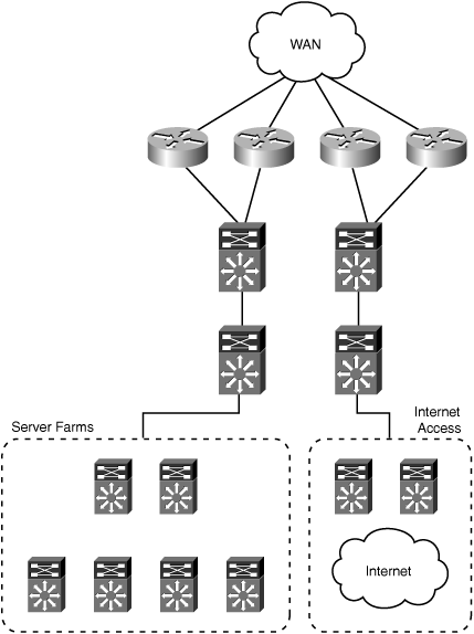
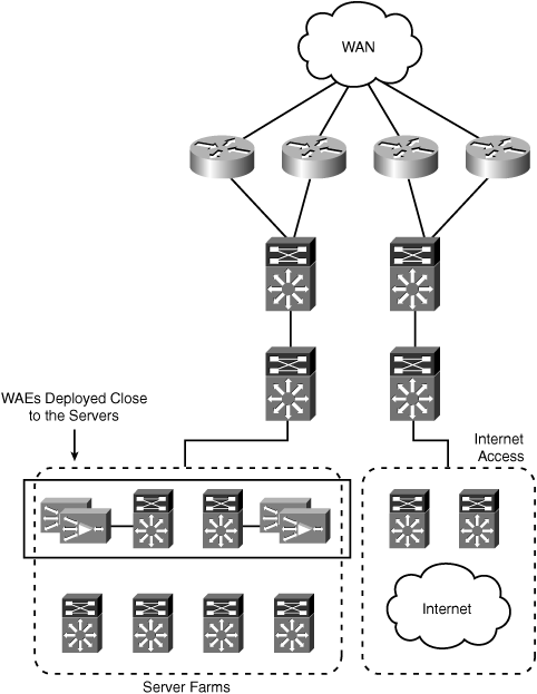
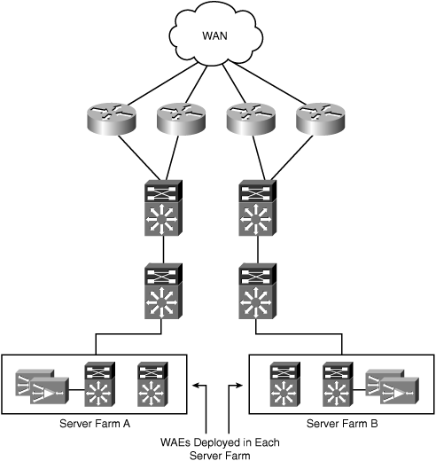
Determining where to deploy WAAS within the data center infrastructure requires careful consideration and planning. Data center environments are generally made up of complex network infrastructures, multiple layers of devices, diverse paths over which traffic can flow, and numerous types of systems performing various functions. This section focuses on where WAAS should be deployed within the data center, irrespective of the interception method used. Subsequent sections in this chapter provide design recommendations and sample configurations for network interception in the data center. Figure 6-1 shows the sample data center topology that will be used as a reference for discussing where within a data center WAAS should be deployed.
Starting from the top of the topology shown in Figure 6-1, traffic enters the data center through any of several Cisco routers located at the WAN edge. All of the WAN edge routers are aggregated into a pair of Cisco Catalyst 6500 Series switches. From there, traffic passes through another pair of Cisco Catalyst 6500 Series switches, which act as the core of the data center network infrastructure. Connecting to the core switches are multiple pairs of distribution switches, each providing connectivity for a different block of resources within the data center. For example, one resource block hosts multiple server farms, while another block provides connectivity to multiple Internet service providers (ISP) for corporate Internet connectivity, and another block could be present, connecting to downstream access layer infrastructure to support campus users.
The first logical location within the data center to consider deploying WAAS is the WAN edge, or the point where traffic from remote branch offices first enters the data center. The benefits to deploying WAAS at this location include:
The WAN edge is a natural aggregation point for traffic destined to or sourced from a remote branch office, and that is a good candidate for optimization. This is an important point, because passing intra-data center traffic through WAAS unnecessarily consumes resources and can potentially constrain throughput.
The WAN edge layer in the data center is less likely to contain other application-aware components, such as firewalls, IDS/IPS, and content switches that require visibility into multiple layers of the traffic flows.
The configuration required to support this deployment model is kept simple, because transparent interception needs to be configured and maintained only in a single location.
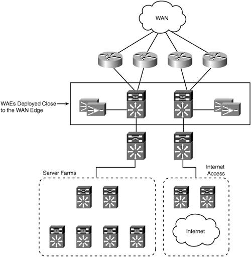
Deploying WAAS at a single aggregation point also provides the best hardware resource utilization, because a single cluster of WAEs can handle optimization and acceleration services for all WAN traffic. Figure 6-2 shows the reference data center topology with WAEs deployed at the WAN edge.
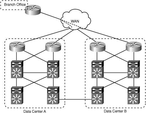
There are, however, reasons that can lead you to deploy WAAS deeper in the data center, that is, farther away from the WAN edge and closer to the server farm or host system. Take for example the topology in Figure 6-3, which shows a sample topology with multiple interconnected data centers.
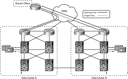
In this example, each remote branch office has WAN connectivity to both data centers. Users in the branch offices access resources in both data centers simultaneously. If the routing policy is such that users always take the most direct path to each data center, then deploying WAAS at the WAN edge in each data center will allow traffic to either data center to be optimized. Figure 6-4 shows sample traffic flows to each data center with WAAS deployed at the WAN edge.
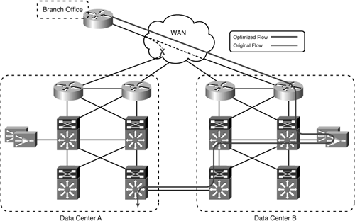
Figure 6-4 shows that, in a steady state, traffic from the remote branch office to either data center is optimized. However, in cases where traffic flows asymmetrically between the remote branch office and the data centers, the WAN edge might not be the best location to deploy WAAS in the data center. Asymmetric traffic flows can be the result of a WAN failure—for example, if the WAN link between the remote branch office and Data Center A in Figure 6-4 were to fail. Asymmetric traffic flows can also be caused by deliberate design; for example, if the routing policy dictates that both WAN links in the branch office are equal cost paths (that is, traffic can enter or leave over either WAN link, regardless of the final destination), all traffic from the branch office to Data Center A will flow across the WAN link to Data Center B, and then across the link between Data Center B and Data Center A. Figure 6-5 shows the traffic flow during a WAN link failure between the branch office and Data Center A.
At the time of the failure, connections that were being optimized between the branch office WAE and the WAEs at the WAN edge in Data Center A would be reset, because the WAEs in Data Center A would no longer see the traffic. Connections between the branch office and Data Center B would continue to be optimized. As users reconnect to resources in Data Center A, the WAEs located in Data Center B would intercept the connections and begin optimization. This same behavior would happen again when the WAN link between the branch office and Data Center A was restored. Connections between hosts in the branch office and Data Center A would begin flowing over the direct connection between the two sites. Because the connections are no longer seen by the WAEs in Data Center B, those connections will be reset. As the connections are reestablished, they will be optimized between the branch office WAE and the WAEs in Data Center A.
Tip
As a general recommendation, when the network topology provides multiple paths over which traffic can flow, the WAAS design should assume that traffic will flow asymmetrically over both paths, even if the current design intends for traffic to flow symmetrically.
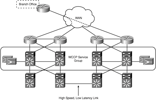
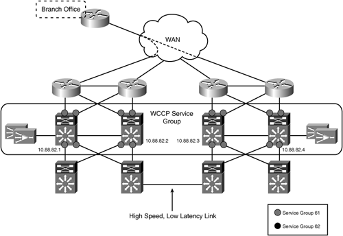
There are two design approaches to handle cases where traffic flows asymmetrically between multiple sites and the WAN edge is not the ideal location to deploy WAAS. The first approach stretches the transparent interception logic across the WAN edge layers in both data centers. This approach ensures that traffic entering or leaving either data center WAN edge is redirected to the same WAE in both directions. The design approach is easily accomplished with WCCP, by configuring a single WCCP service group that spans the WAN edge layer of both data centers. Figure 6-6 shows the use of a single WCCP service group to encompass the WAN edge layer of both data centers.
This design approach assumes that the data centers are “well connected”—that is, the connectivity between data centers is high bandwidth (>100 Mbps) and low latency (<10 msec). In essence, the WAEs in both data centers act as a single logical cluster. This design and the associated configurations are discussed in more detail later in this chapter.
The second design approach involves moving the location where WAAS is deployed closer toward the host resources and away from the WAN edge. In this topology, WAAS should be deployed behind the point in the data center topology where the two data centers are interconnected. Moving the WAEs and interception configuration behind the point of connectivity between the data centers eliminates the potential for traffic to only be seen in a single direction by the data center WAEs. Figure 6-7 shows the reference topology with WAAS deployed behind the point of asymmetric traffic flows.
As you consider moving WAAS away from the WAN edge and deeper into the data center, you need to take into consideration other components in the data center that rely on access to various pieces of information in the traffic flow. These other components can include firewalls, IDS/IPS, and content switches, just to name a few. Understanding the traffic visibility requirements of these devices is required as part of the design process.
Consider the example of a content switch, such as the Application Control Engine (ACE). If ACE intercepts traffic for load balancing before it is intercepted by WAAS, there is the potential that information within the packet that ACE relies on to make a load-balancing decision will be obscured. Because this example is dealing with HTTP traffic, the default policy action in WAAS is Full Optimization (TFO+DRE+LZ). This means that the payload of the TCP segment will be compressed, and will not be readable by the load-balancing functions in ACE. If ACE is configured to make a load-balancing decision based on content in the Layer 7 HTTP header, it will not have access to that information. In this case, the WAEs need to be deployed in front of the ACE modules, so that the optimized connections are terminated prior to being intercepted by ACE for load balancing. This is just one example of how other application-aware components in the data center can potentially conflict with the optimizations provided by WAAS. Understanding the capabilities of these components, and their architectural placement within the data center, is a key design consideration.
Another key consideration as you look at deploying WAAS closer to the server farm is the impact on sizing—that is, the number of WAEs required in the data center to support the solution deployment. When WAAS devices are deployed at a common aggregation point for all traffic, a single cluster of WAEs can be used. If you move WAAS closer to the server farm infrastructure, and, due to the network topology, end up configuring interception at multiple locations in the data center, the number of WAEs required to support the design could increase. Figure 6-8 shows an example topology where WAAS has been deployed in multiple server farm distribution blocks.
The impact on sizing of splitting the design into multiple clusters within the data center is two-fold:
Redundancy for each cluster must be accounted for separately. Data center deployments generally use n+1 sizing, where n is the number of WAEs required to support the expected load. The “+1” provides an additional WAE, which allows for the failure of a single WAE in the cluster without losing any cluster resource capacity. When you have multiple WAE clusters in the data center, having the same redundancy requirements means that each cluster is sized for n+1. This increases the number of WAEs required in the data center by the number separate WAE clusters that are deployed.
Depending on what is driving the number of WAEs required in the data center, you could end up having to replicate the same number of WAEs in each separate cluster. For example, in a large deployment with 1000 remote branch offices, it is possible that the number of peer WAEs is the determining factor in how many WAEs are deployed in the data center. If the data center design calls for two separate clusters of WAEs, one for each server farm, and all of the remote branches are talking to resources in both server farms concurrently, then each cluster will need the same number of WAEs to support the fan-out ratio.
The following section discusses the specific network interception design options and associated configurations for the data center environment.
This section provides the design and configuration details for deploying WAAS with transparent interception in the data center. The two transparent interception methods discussed are WCCP and content switching. The content switching design includes the Application Control Engine (ACE) from Cisco.
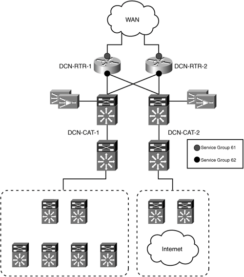
WCCP provides a scalable and transparent interception method suitable for both the remote branch office and data center environments. Figure 6-9 shows the reference data center topology with WCCP enabled on the WAN edge routers.
This case assumes that traffic flows symmetrically through the WAN edge in a single data center. Note that the placement of service groups 61 and 62 in the configuration is reversed from the branch office configuration. In the data center, service group 61 is configured on the WAN-facing interfaces, while service group 62 is configured on the LAN-facing interfaces.
This ensures that the load-distribution decision is based on the client IP address end-to-end. This is discussed in more detail in the section, “Scaling Transparent Interception” later in this chapter.
In Figure 6-9, WCCP is enabled on the Cisco WAN edge routers. The WAEs are connected to the WAN distribution switches on their own VLAN. WCCP is configured for GRE forwarding and hash assignment. To preserve the original path selection, and prevent the possibility of a redirection loop, the egress method is configured for negotiated return. This ensures that egress traffic from the WAEs is returned to the intercepting router after processing. Example 6-1 shows the relevant portions of each WAN edge router configuration for this deployment model.
Example 6-1. WAN Edge Router WCCP Configuration
!
hostname DCN-RTR-1
!
ip wccp 61 password cisco
ip wccp 62 password cisco
!
ip cef
!
interface Loopback0
 ip address 10.88.81.1 255.255.255.255
 no ip unreachables
!
interface GigabitEthernet0/1
 ** Link to DCN-CAT-1 **
 ip address 10.88.80.1 255.255.255.252
 ip wccp 62 redirect in
 duplex auto
 speed auto
 media-type gbic
 negotiation auto
!
interface GigabitEthernet0/2
 ** Link to DCN-CAT-2 **
 ip address 10.88.80.5 255.255.255.252
 ip wccp 62 redirect in
 duplex auto
 speed auto
 media-type gbic
 negotiation auto
!
interface ATM1/0
 no ip address
 load-interval 30
 no atm scrambling sts-stream
 no atm ilmi-keepalive
!
interface ATM1/0.55 point-to-point
 description ** 45 Mbps PVC to MPLS Service **
 bandwidth 45000
 ip address 10.19.176.5 255.255.255.252
 ip wccp 61 redirect in
 no snmp trap link-status
 pvc 1/55
  vbr-nrt 44209 44209
  broadcast
  encapsulation aal5snap
 !
!
!
hostname DCN-RTR-2
!
ip wccp 61 password cisco
ip wccp 62 password cisco
!
ip cef
!
interface Loopback0
 ip address 10.88.81.2 255.255.255.255
 no ip unreachables
!
interface GigabitEthernet0/1
 ** Link to DCN-CAT-2 **
 ip address 10.88.80.9 255.255.255.252
 ip wccp 62 redirect in
 duplex auto
 speed auto
 media-type gbic
 negotiation auto
!
interface GigabitEthernet0/2
 ** Link to DCN-CAT-1 **
 ip address 10.88.80.13 255.255.255.252
 ip wccp 62 redirect in
 duplex auto
 speed auto
 media-type gbic
 negotiation auto
!
interface ATM1/0
 no ip address
 load-interval 30
 no atm scrambling sts-stream
 no atm ilmi-keepalive
!
interface ATM1/0.55 point-to-point
 description ** 45 Mbps PVC to MPLS Service **
 bandwidth 45000
 ip address 10.19.176.9 255.255.255.252
 ip wccp 61 redirect in
 no snmp trap link-status
 pvc 1/55
  vbr-nrt 44209 44209
  broadcast
  encapsulation aal5snap
 !
!
Example 6-2 shows a sample configuration for a WAE in this deployment model.
Example 6-2. WCCP in WAN Edge Routers WAE Configuration
!
device mode application-accelerator
!
hostname DCN-WAE-1
!
ip domain-name asdcnp-waas.cisco.com
!
primary-interface GigabitEthernet 1/0
!
interface GigabitEthernet 1/0
 ip address 10.74.155.11 255.255.255.0
 exit
interface GigabitEthernet 2/0
 shutdown
 exit
!
ip default-gateway 10.74.155.1
!
no auto-register enable
!
! ip path-mtu-discovery is disabled in WAAS by default
!
ip name-server 10.88.80.53
!
ntp server 10.88.121.253
!
wccp router-list 1 10.88.81.1 10.88.81.2
wccp tcp-promiscuous router-list-num 1 password cisco
wccp version 2
!
egress-method negotiated-return intercept-method wccp
!
authentication login local enable primary
authentication configuration local enable primary
!
central-manager address 10.88.80.133
cms enable
!
no adapter epm enable
!
<ATP Configuration Removed>
!
! End of WAAS configuration
To take advantage of hardware-accelerated interception, WCCP can be configured on the WAN distribution switches instead of the WAN edge routers. Figure 6-10 shows the reference data center topology with WCCP enabled on the WAN distribution switches.
WCCP is enabled on the Cisco WAN distribution switches. The WAEs are directly connected to the WAN distribution switches on a dedicated VLAN, which is trunked between the two switches. This ensures that there is a Layer 2 adjacency between both switches and all WAEs in the service group. WCCP is configured for L2 forwarding and mask assignment. For performance reasons, the egress method is configured for IP forwarding. To distribute load across both WAN distribution switches, Multigroup HRSP is configured on the WAE VLAN. The default gateway configured on the WAEs in the cluster is balanced between the two HSRP VIPs. Example 6-3 shows the relevant portions of each WAN distribution switch configuration for this deployment model.
Example 6-3. WAN Distribution Switch WCCP Configuration
!
hostname DCN-CAT-1
!
ip wccp 61 password cisco accelerated
ip wccp 62 password cisco accelerated
!
vlan 65
!
interface Port-channel50
 description ** PC between CAT-1 to CAT-2 **
 switchport
 switchport trunk encapsulation dot1q
 switchport trunk allowed vlan 1,65
 switchport mode trunk
 no ip address
!
interface GigabitEthernet1/1
 description ** Link to DCN-RTR-1 **
 ip address 10.88.80.2 255.255.255.252
 ip wccp 61 redirect in
!
interface GigabitEthernet1/2
 description ** Link to DCN-RTR-2 **
 ip address 10.88.80.6 255.255.255.252
 ip wccp 61 redirect in
!
interface GigabitEthernet1/3
 switchport
 switchport access vlan 65
 switchport mode access
 no ip address
 spanning-tree portfast
!
interface GigabitEthernet1/4
 switchport
 switchport access vlan 65
 switchport mode access
 no ip address
 spanning-tree portfast
!
interface GigabitEthernet1/5
 switchport
 switchport access vlan 65
 switchport mode access
 no ip address
 spanning-tree portfast
!
interface GigabitEthernet1/6
 switchport
 switchport access vlan 65
 switchport mode access
 no ip address
 spanning-tree portfast
!
interface GigabitEthernet1/41
 description ** Link to DCN-CORE-1 **
 ip address 10.88.80.17 255.255.255.252
 ip wccp 62 redirect in
!
interface GigabitEthernet1/42
 description ** Link to DCN-CORE-2 **
 ip address 10.88.80.21 255.255.255.252
 ip wccp 62 redirect in
!
interface GigabitEthernet1/47
 description CAT-1 to CAT-2 LINKS
 switchport
 switchport trunk encapsulation dot1q
 switchport trunk allowed vlan 1,65
 switchport mode trunk
 no ip address
 channel-group 50 mode desirable
!
interface GigabitEthernet1/48
 description CAT-1 to CAT-2 LINKS
 switchport
 switchport trunk encapsulation dot1q
 switchport trunk allowed vlan 1,65
 switchport mode trunk
 no ip address
 channel-group 50 mode desirable
!
interface Vlan1
 no ip address
 shutdown
!
interface Vlan65
 description ** WAAS WAE Vlan **
 ip address 10.74.155.3 255.255.255.0
 standby 1 ip 10.74.155.1
 standby 1 priority 105
 standby 1 preempt
 standby 2 ip 10.74.155.2
!
!
hostname DCN-CAT-2
!
ip wccp 61 password cisco accelerated
ip wccp 62 password cisco accelerated
!
vlan 65
!
interface Port-channel50
 description ** PC between CAT-2 to CAT-1 **
 switchport
 switchport trunk encapsulation dot1q
 switchport trunk allowed vlan 1,65
 switchport mode trunk
 no ip address
!
interface GigabitEthernet1/1
 description ** Link to DCN-RTR-2 **
 ip address 10.88.80.10 255.255.255.252
 ip wccp 61 redirect in
!
interface GigabitEthernet1/2
 description ** Link to DCN-RTR-1 **
 ip address 10.88.80.14 255.255.255.252
 ip wccp 61 redirect in
!
interface GigabitEthernet1/3
 switchport
 switchport access vlan 65
 switchport mode access
 no ip address
 spanning-tree portfast
!
interface GigabitEthernet1/4
 switchport
 switchport access vlan 65
 switchport mode access
 no ip address
 spanning-tree portfast
!
interface GigabitEthernet1/5
 switchport
 switchport access vlan 65
 switchport mode access
 no ip address
 spanning-tree portfast
!
interface GigabitEthernet1/6
 switchport
 switchport access vlan 65
 switchport mode access
 no ip address
 spanning-tree portfast
!
interface GigabitEthernet1/41
 description ** Link to DCN-CORE-2 **
 ip address 10.88.80.25 255.255.255.252
 ip wccp 62 redirect in
!
interface GigabitEthernet1/42
 description ** Link to DCN-CORE-1 **
 ip address 10.88.80.29 255.255.255.252
 ip wccp 62 redirect in
!
interface GigabitEthernet1/47
 description CAT-2 to CAT-1 LINKS
 switchport
 switchport trunk encapsulation dot1q
 switchport trunk allowed vlan 1,65
 switchport mode trunk
 no ip address
 channel-group 50 mode desirable
!
interface GigabitEthernet1/48
 description CAT-1 to CAT-2 LINKS
 switchport
 switchport trunk encapsulation dot1q
 switchport trunk allowed vlan 1,65
 switchport mode trunk
 no ip address
 channel-group 50 mode desirable
!
interface Vlan1
 no ip address
 shutdown
!
interface Vlan65
 description ** WAAS WAE Vlan **
 ip address 10.74.155.4 255.255.255.0
 standby 1 ip 10.74.155.1
 standby 1 preempt
 standby 2 ip 10.74.155.2
 standby 2 priority 105
!
Example 6-4 shows a sample configuration for a WAE in this deployment model.
Example 6-4. WCCP on WAN Distribution Switches WAE Configuration
!
device mode application-accelerator
!
hostname DCN-WAE-1
!
ip domain-name asdcnp-waas.cisco.com
!
primary-interface GigabitEthernet 1/0
!
interface GigabitEthernet 1/0
 ip address 10.74.155.11 255.255.255.0
 exit
interface GigabitEthernet 2/0
 shutdown
 exit
!
ip default-gateway 10.74.155.1
!
no auto-register enable
!
! ip path-mtu-discovery is disabled in WAAS by default
!
ip name-server 10.88.80.53
!
ntp server 10.88.121.253
!
wccp router-list 1 10.74.155.3 10.74.155.4
wccp tcp-promiscuous router-list-num 1 l2-redirect mask-assign password cisco
wccp version 2
!
authentication login local enable primary
authentication configuration local enable primary
!
central-manager address 10.88.80.133
cms enable
!
no adapter epm enable
!
<ATP Configuration Removed>
!
! End of WAAS configuration
This same configuration could be used when deploying WAAS deeper in the data center, toward the server farms.
As discussed in the previous section, deploying WAAS in the WAN distribution layer when multiple data centers and asymmetric routing are involved requires that the WCCP service group span the WAN edge routers or switches in both data centers. Figure 6-11 shows a sample data center topology with a single WCCP service group that includes the WAN distribution switches in both data centers.
WCCP is enabled on the Cisco WAN distribution switches. The WAEs are directly connected to the WAN distribution switches on a dedicated VLAN, which is trunked between the two switches in the local data center. All of the WAEs in both data centers register with each pair of WAN distribution switches in both data centers. WCCP is configured for GRE forwarding and mask assignment. For performance reasons, the egress method is configured for IP forwarding. Each WAE uses the local WAN distribution switches as their default gateway. Example 6-5 shows a sample configuration for a WAE in this deployment model.
Example 6-5. Dual Data Center WAE Configuration
!
device mode application-accelerator
!
hostname DCN-WAE-1
!
ip domain-name asdcnp-waas.cisco.com
!
primary-interface GigabitEthernet 1/0
!
interface GigabitEthernet 1/0
 ip address 10.74.155.11 255.255.255.0
 exit
interface GigabitEthernet 2/0
 shutdown
 exit
!
ip default-gateway 10.74.155.1
!
no auto-register enable
!
! ip path-mtu-discovery is disabled in WAAS by default
!
ip name-server 10.88.80.53
!
ntp server 10.88.121.253
!
wccp router-list 1 10.88.82.1 10.88.82.2 10.88.82.3 10.88.82.4
wccp tcp-promiscuous router-list-num 1 mask-assign password cisco
wccp version 2
!
authentication login local enable primary
authentication configuration local enable primary
!
central-manager address 10.88.80.133
cms enable
!
no adapter epm enable
!
<ATP Configuration Removed>
!
! End of WAAS configuration
Using a content switch, such as ACE, provides an alternative to WCCP for transparent interception in the data center. ACE is best suited for designs where WCCP is unable to meet the scalability requirements of the deployment, or in data center designs where virtualization is used to provide logically separate infrastructures for different types of traffic. ACE can be deployed in either bridged mode or routed mode. Bridged mode is the equivalent of having ACE inline, as it bridges all traffic between VLANs. Routed mode requires that traffic be forwarded to ACE as a Layer 3 next hop. This is done by having traffic destined to a virtual IP address hosted on ACE, or using policy-based routing (PBR) to redirect traffic to ACE. Design and configuration examples of deploying ACE in bridged and routed mode for WAAS interception are provided in this section.
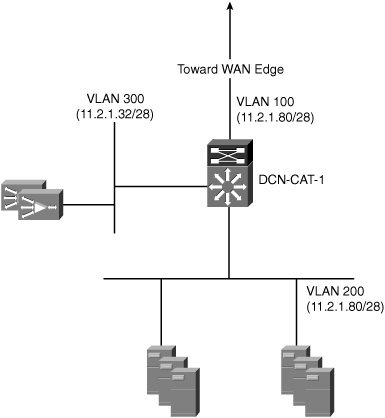
Figure 6-12 shows a topology where ACE is deployed in bridged mode at the server farm distribution layer.
In this deployment model, ACE bridges all traffic between VLAN 100 and VLAN 200. All traffic flows through ACE, regardless of whether or not the traffic is intercepted and redirected to a WAE for optimization. When the packet arrives on VLAN 100 in the Catalyst 6500 switch, it is passed through to the ACE module. A service policy configured to intercept all TCP traffic redirects the packet to one of the WAEs in the WAAS cluster. The WAE selected by the ACE load-balancing algorithm records the packet TCP options, and returns the packet to its configured default gateway, which is the IP address configured on the WAAS VLAN in ACE. ACE forwards the packet based on the destination IP address and its routing configuration.
When a SYN-ACK response from the origin server arrives on VLAN 200, it is matched against the original flow created when the SYN packet was intercepted by ACE. Because the WAAS VLAN is configured with mac-sticky, the ACE returns the packet back to the WAE that handled the original SYN packet. The WAE matches the SYN-ACK with the original SYN packet and continues the TFO auto-discovery process. The packet is then returned to the ACE and routed back toward the WAN edge.
Example 6-6 shows the Catalyst 6500 and ACE configuration for this deployment model.
Example 6-6. Catalyst 6500 and ACE Bridged Mode Configuration
!
hostname DCN-CAT-1
!
svclc multiple-vlan-interfaces
svclc module 1 vlan-group 10
svclc vlan-group 10 100,200,300
!
interface Vlan100
 description ** Client-Side VLAN **
 ip address 11.2.1.81 255.255.255.240
!
!
hostname DCN-ACE-1
!
arp interval 15
!
access-list PERMIT-ALL line 10 extended permit ip any any
access-list PERMIT-ALL line 20 extended permit icmp any any
!
rserver host DCN-WAE-2
  ip address 11.2.1.34
  inservice
rserver host DCN-WAE-2
  ip address 11.2.1.35
  inservice
!
serverfarm host WAAS
  transparent
  predictor hash address source
  rserver DCN-WAE-1
    inservice
  rserver DCN-WAE-2
    inservice
!
class-map match-any ALL-TCP
  description ** Match all TCP traffic **
  10 match virtual-address 0.0.0.0 0.0.0.0 tcp any
!
class-map type management match-any ACE-MANAGEMENT
  2 match protocol telnet any
  3 match protocol ssh any
  4 match protocol icmp any
class-map match-any TCP-ALL
  2 match virtual-address 0.0.0.0 0.0.0.0 tcp any
!
policy-map type management first-match ACE-MANAGEMENT
  class ACE-MANAGEMENT
    permit
policy-map type loadbalance first-match TCP-ALL
  class class-default
    serverfarm WAAS
policy-map multi-match WAAS-INTERCEPTION
  class TCP-ALL
    loadbalance vip inservice
    loadbalance policy TCP-ALL
!
service-policy input ACE-MANAGEMENT
!
interface vlan 300
  description ** WAAS WAE VLAN **
  ip address 11.2.1.40 255.255.255.240
  no normalization
  mac-sticky enable
  access-group input PERMIT-ALL
  access-group output PERMIT-ALL
  no shutdown
interface vlan 100
  description ** Client-Side VLAN **
  bridge-group 100
  no normalization
  access-group input PERMIT-ALL
  access-group output PERMIT-ALL
  service-policy input WAAS-INTERCEPT
  no shutdown
interface vlan 200
  description ** Server-Side VLAN **
  bridge-group 100
  no normalization
  access-group input PERMIT-ALL
  access-group output PERMIT-ALL
  service-policy input WAAS-INTERCEPT
  no shutdown
!
interface bvi 100
  ip address 11.2.1.83 255.255.255.240
  no shutdown
!
ip route 0.0.0.0 0.0.0.0 11.2.1.81
!
IP normalization is also disabled on the ACE VLAN interfaces with the command no normalization. This is required to allow the WAAS TFO auto-discovery process to function properly.
No special configuration is required on the WAE when ACE is used for interception. The default gateway configured on the WAE is the alias IP address of the WAE VLAN configured in ACE.
When ACE is deployed in routed mode, ACE must become a Layer 3 next hop for traffic in order for interception to take place. Because WAAS is transparent at Layer 3, traffic will not be destined to a VIP configured on ACE. For this deployment model, ACE is used in combination with PBR to intercept interesting traffic for optimization. PBR is configured in the network infrastructure devices, with a next-hop IP address of a VLAN interface on ACE.
The routed mode topology is similar to bridged mode, the primary difference being how traffic is intercepted by ACE. In the routed mode deployment, PBR is configured on the Catalyst 6500 switch to intercept TCP traffic that will be optimized by WAAS. The PBR configuration sets a next-hop address of an IP address configured on the ACE module. The WAEs are placed on a dedicated VLAN that is routed by the ACE module. Example 6-7 shows the ACE configuration for this deployment model.
Example 6-7. Catalyst 6500 and ACE Routed Mode Configuration
!
hostname DCN-CAT-1
!
vlan 500
!
interface Vlan100
 description ** Link to Data Center WAN Edge **
 ip address 10.88.81.6 255.255.255.252
 ip policy route-map PBR-TO-ACE
!
interface Vlan200
 ip address 172.16.0.1 255.255.254.0
 ip policy route-map PBR-TO-ACE
!
interface Vlan500
 description ** Lini to DCN-ACE-1 **
 ip address 30.30.5.4 255.255.255.0
!
ip access-list extended PBR-TO-ACE
 permit tcp any any
!
route-map PBR-TO-ACE permit 10
 match ip address PBR-TO-ACE
 set ip next-hop 30.30.5.1
!
!
hostname DCN-ACE-1
!
arp interval 15
!
access-list PERMIT-ALL line 10 extended permit ip any any
access-list PERMIT-ALL line 20 extended permit icmp any any
!
rserver host DCN-WAE-1
  ip address 30.30.51.10
  inservice
rserver host DCN-WAE-2
  ip address 30.30.51.11
  inservice
!
serverfarm host WAAS
  transparent
  rserver DCN-WAE-1
    inservice
  rserver DCN-WAE-2
    inservice
!
class-map type management match-any ACE-MANAGEMENT
  2 match protocol telnet any
  3 match protocol ssh any
  4 match protocol icmp any
class-map match-any TCP-ALL
  2 match virtual-address 0.0.0.0 0.0.0.0 tcp any
!
policy-map type management first-match ACE-MANAGEMENT
  class ACE-MANAGEMENT
    permit
policy-map type loadbalance first-match TCP-ALL
  class class-default
    serverfarm WAAS
policy-map multi-match WAAS-INTERCEPTION
  class TCP-ALL
    loadbalance vip inservice
    loadbalance policy TCP-ALL
!
service-policy input ACE-MANAGEMENT
!
interface vlan 500
  description ** Client-Side VLAN **
  ip address 30.30.5.1 255.255.255.0
  no normalization
  access-group input PERMIT-ALL
  access-group output PERMIT-ALL
  service-policy input WAAS-INTERCEPTION
  no shutdown
interface vlan 501
  description ** WAAS WAE VLAN **
  ip address 30.30.51.1 255.255.255.0
  no normalization
  mac-sticky enable
  access-group input PERMIT-ALL
  access-group output PERMIT-ALL
  no shutdown
!
ip route 0.0.0.0 0.0.0.0 30.30.5.4
!
Again, no special configuration is required on the WAE when ACE is used for interception. The default gateway configured on the WAE is the IP address of the WAE VLAN configured in ACE.
As organizations continue to consolidate more and more IT resources into the data center, the data center becomes a natural aggregation point for traffic from the remote branch offices. Due to the high traffic volumes, diverse routing paths, and increasing number of data center resources accessed from remote branch offices, in-path deployment models are not considered a scalable solution for data center environments. The preferred transparent interception method in data center environments is either WCCP or ACE/CSM. Both of these interception methods provide the availability and scalability features required to support large-scale WAAS deployments. Each interception method, along with best practice recommendations and configuration examples, is discussed in turn in the following sections.
The placement of services 61 and 62 in the router configuration plays an important role in the scalability of the WAAS solution. When multiple WAEs are deployed in the branch, the goal is to distribute load across the WAEs in the service group as evenly as possible. The TCP promiscuous services perform load distribution at IP address–level granularity. In most environments, the number of clients is far greater than the number of servers; therefore, performing load distribution based on the client IP address makes it statistically more likely that clients will be distributed more evenly across multiple WAEs. In contrast, if load is distributed based on server IP address, the effectiveness of DRE could potentially increase, because all content for a single server IP address would reside in a single WAE. However, using the server IP address does not allow for linear scalability of the solution. In addition, there is a potential for “hot spots,” where in a cluster of WAEs only one or two WAEs are used for the majority of traffic. This can happen due to the limited number of server IP addresses, and the potential for virtual IP addresses, proxy addresses, and other heavily used destination IP addresses being pinned to a single WAE.
The hash function used by WCCP hash assignment is designed to distribute client load across all of the WAEs in a service group. Although this is appropriate for branch office deployments, load distribution in the data center must also take into consideration the fan-out ratio. Take for example a branch office with hosts using IP addresses in the 10.48.136.0/23 network. In the data center there are three WAEs deployed in a cluster. Example 6-8 shows the hash bucket distribution for each of the three WAEs.
Example 6-8. Data Center WAE Hash Bucket Distribution
AST6-RTR-02# show ip wccp 61 detail
WCCP Client information:
        WCCP Client ID:          10.88.81.2
        Protocol Version:        2.0
        State:                   Usable
        Initial Hash Info:       00000000000000000000000000000000
                                 00000000000000000000000000000000
        Assigned Hash Info:      FFFFFFFFFFFFFFFFFFFFFC0000000000
                                 00000000000000000000000000000000
        Hash Allotment:          86 (33.59%)
        Packets s/w Redirected:  0
        Connect Time:            1d22h
        Bypassed Packets
          Process:               0
          Fast:                  0
          CEF:                   0
        WCCP Client ID:          10.88.80.138
        Protocol Version:        2.0
        State:                   Usable
        Initial Hash Info:       00000000000000000000000000000000
                                 00000000000000000000000000000000
        Assigned Hash Info:      00000000000000000000000000000000
                                 FFFFFFFFFFFFFFFFFFFFF80000000000
        Hash Allotment:          85 (33.20%)
        Packets s/w Redirected:  0
        Connect Time:            00:01:55
        Bypassed Packets
          Process:               0
          Fast:                  0
          CEF:                   0
        WCCP Client ID:          10.88.80.137
        Protocol Version:        2.0
        State:                   Usable
        Initial Hash Info:       00000000000000000000000000000000
                                 00000000000000000000000000000000
        Assigned Hash Info:      0000000000000000000003FFFFFFFFFF
                                 0000000000000000000007FFFFFFFFFF
        Hash Allotment:          85 (33.20%)
        Packets s/w Redirected:  0
        Connect Time:            00:00:50
        Bypassed Packets
          Process:               0
          Fast:                  0
          CEF:                   0
AST6-RTR-02#
In the preceding output, each WAE has received roughly 33 percent of the hash buckets in the table. Which data center WAE they will be redirected to can be determined by looking at a small sample of client IP addresses from the branch network. Example 6-9 shows the results of this test.
Example 6-9. Client Distribution Across Data Center WAEs
AST6-RTR-02# show ip wccp 61 hash 0.0.0.0 10.48.136.10 0 0
WCCP hash information for:
    Primary Hash:   Src IP: 10.48.136.10
        Bucket: 184
    WCCP Client: 10.88.81.2
AST6-RTR-02#
AST6-RTR-02# show ip wccp 61 hash 0.0.0.0 10.48.136.50 0 0
WCCP hash information for:
    Primary Hash:   Src IP: 10.48.136.50
        Bucket: 128
    WCCP Client: 10.88.80.137
AST6-RTR-02# show ip wccp 61 hash 0.0.0.0 10.48.136.200 0 0
WCCP hash information for:
    Primary Hash:   Src IP: 10.48.136.200
        Bucket: 122
    WCCP Client: 10.88.80.138
AST6-RTR-02# show ip wccp 61 hash 0.0.0.0 10.48.137.20 0 0
WCCP hash information for:
    Primary Hash:   Src IP: 10.48.137.20
        Bucket: 167
    WCCP Client: 10.88.80.137
AST6-RTR-02# show ip wccp 61 hash 0.0.0.0 10.48.137.70 0 0
WCCP hash information for:
    Primary Hash:   Src IP: 10.48.137.70
        Bucket: 245
    WCCP Client: 10.88.81.2
AST6-RTR-02# show ip wccp 61 hash 0.0.0.0 10.48.137.222 0 0
WCCP hash information for:
    Primary Hash:   Src IP: 10.48.137.222
        Bucket: 109
    WCCP Client: 10.88.80.138
AST6-RTR-02#
You can see from the output that clients from a single branch are redirected to all three WAEs in the data center cluster. This results in a DRE context for the branch office WAE in every data center WAE. While this may not pose a problem for small and medium-sized WAAS deployments, as you start to scale to hundreds or thousands of WAEs, keeping a DRE context for every remote WAE in every data center WAE does not scale. For example, if you have a WAAS deployment made up of 350 remote branch offices, you may choose to deploy three WAE-7341s in the data center to support the fan-out ratio. However, when hash assignment is used, each of the three WAE-7341s will likely have a peer relationship with all 350 remote branch WAEs. Therefore, when the number of remote WAEs in a deployment exceeds the fan-out ratio supported by a single WAE in the data center, hash assignment is not recommended.
With WCCP mask assignment, you can influence the load distribution by adjusting the position of the bit in the mask to take only the network portion of the IP address into consideration. Example 6-10 shows the mask/value set distribution across the three WAEs in the data center.
Example 6-10. Data Center WAE Mask/Value Distribution
DCN-CAT-8# show ip wccp 61 detail
WCCP Cache-Engine information:
      Web Cache ID:          10.88.81.2
      Protocol Version:      2.0
      State:                 Usable
      Redirection:           GRE
      Packet Return:         GRE
      Packets Redirected:    0
      Connect Time:          00:02:53
      Assignment:            MASK
      Mask  SrcAddr    DstAddr    SrcPort DstPort
      ----  -------    -------    ------- -------
      0000: 0x00001741 0x00000000 0x0000  0x0000
      Value SrcAddr    DstAddr    SrcPort DstPort CE-IP
      ----- -------    -------    ------- ------- -----
      0042: 0x00001240 0x00000000 0x0000  0x0000  0x0A585102 (10.88.81.2)
      0043: 0x00001241 0x00000000 0x0000  0x0000  0x0A585102 (10.88.81.2)
      0044: 0x00001300 0x00000000 0x0000  0x0000  0x0A585102 (10.88.81.2)
      0045: 0x00001301 0x00000000 0x0000  0x0000  0x0A585102 (10.88.81.2)
      0046: 0x00001340 0x00000000 0x0000  0x0000  0x0A585102 (10.88.81.2)
      0047: 0x00001341 0x00000000 0x0000  0x0000  0x0A585102 (10.88.81.2)
      0048: 0x00001400 0x00000000 0x0000  0x0000  0x0A585102 (10.88.81.2)
      0049: 0x00001401 0x00000000 0x0000  0x0000  0x0A585102 (10.88.81.2)
      0050: 0x00001440 0x00000000 0x0000  0x0000  0x0A585102 (10.88.81.2)
      0051: 0x00001441 0x00000000 0x0000  0x0000  0x0A585102 (10.88.81.2)
      0052: 0x00001500 0x00000000 0x0000  0x0000  0x0A585102 (10.88.81.2)
      0053: 0x00001501 0x00000000 0x0000  0x0000  0x0A585102 (10.88.81.2)
      0054: 0x00001540 0x00000000 0x0000  0x0000  0x0A585102 (10.88.81.2)
      0055: 0x00001541 0x00000000 0x0000  0x0000  0x0A585102 (10.88.81.2)
      0056: 0x00001600 0x00000000 0x0000  0x0000  0x0A585102 (10.88.81.2)
      0057: 0x00001601 0x00000000 0x0000  0x0000  0x0A585102 (10.88.81.2)
      0058: 0x00001640 0x00000000 0x0000  0x0000  0x0A585102 (10.88.81.2)
      0059: 0x00001641 0x00000000 0x0000  0x0000  0x0A585102 (10.88.81.2)
      0060: 0x00001700 0x00000000 0x0000  0x0000  0x0A585102 (10.88.81.2)
      0061: 0x00001701 0x00000000 0x0000  0x0000  0x0A585102 (10.88.81.2)
      0062: 0x00001740 0x00000000 0x0000  0x0000  0x0A585102 (10.88.81.2)
      0063: 0x00001741 0x00000000 0x0000  0x0000  0x0A585102 (10.88.81.2)

      Web Cache ID:          10.88.80.137
      Protocol Version:      2.0
      State:                 Usable
      Redirection:           GRE
      Packet Return:         GRE
      Packets Redirected:    0
      Connect Time:          00:01:44
      Assignment:            MASK
      Mask  SrcAddr    DstAddr    SrcPort DstPort
      ----  -------    -------    ------- -------
      0000: 0x00001741 0x00000000 0x0000  0x0000
      Value SrcAddr    DstAddr    SrcPort DstPort CE-IP
      ----- -------    -------    ------- ------- -----
      0011: 0x00000241 0x00000000 0x0000  0x0000  0x0A585089 (10.88.80.137)
      0012: 0x00000300 0x00000000 0x0000  0x0000  0x0A585089 (10.88.80.137)
      0013: 0x00000301 0x00000000 0x0000  0x0000  0x0A585089 (10.88.80.137)
      0014: 0x00000340 0x00000000 0x0000  0x0000  0x0A585089 (10.88.80.137)
      0015: 0x00000341 0x00000000 0x0000  0x0000  0x0A585089 (10.88.80.137)
      0016: 0x00000400 0x00000000 0x0000  0x0000  0x0A585089 (10.88.80.137)
      0017: 0x00000401 0x00000000 0x0000  0x0000  0x0A585089 (10.88.80.137)
      0018: 0x00000440 0x00000000 0x0000  0x0000  0x0A585089 (10.88.80.137)
      0019: 0x00000441 0x00000000 0x0000  0x0000  0x0A585089 (10.88.80.137)
      0020: 0x00000500 0x00000000 0x0000  0x0000  0x0A585089 (10.88.80.137)
      0021: 0x00000501 0x00000000 0x0000  0x0000  0x0A585089 (10.88.80.137)
      0022: 0x00000540 0x00000000 0x0000  0x0000  0x0A585089 (10.88.80.137)
      0023: 0x00000541 0x00000000 0x0000  0x0000  0x0A585089 (10.88.80.137)
      0024: 0x00000600 0x00000000 0x0000  0x0000  0x0A585089 (10.88.80.137)
      0025: 0x00000601 0x00000000 0x0000  0x0000  0x0A585089 (10.88.80.137)
      0026: 0x00000640 0x00000000 0x0000  0x0000  0x0A585089 (10.88.80.137)
      0027: 0x00000641 0x00000000 0x0000  0x0000  0x0A585089 (10.88.80.137)
      0028: 0x00000700 0x00000000 0x0000  0x0000  0x0A585089 (10.88.80.137)
      0029: 0x00000701 0x00000000 0x0000  0x0000  0x0A585089 (10.88.80.137)
      0030: 0x00000740 0x00000000 0x0000  0x0000  0x0A585089 (10.88.80.137)
      0031: 0x00000741 0x00000000 0x0000  0x0000  0x0A585089 (10.88.80.137)
      Web Cache ID:          10.88.80.138
      Protocol Version:      2.0
      State:                 Usable
      Redirection:           GRE
      Packet Return:         GRE
      Packets Redirected:    0
      Connect Time:          00:00:44
      Assignment:            MASK
      Mask  SrcAddr    DstAddr    SrcPort DstPort
      ----  -------    -------    ------- -------
      0000: 0x00001741 0x00000000 0x0000  0x0000
      Value SrcAddr    DstAddr    SrcPort DstPort CE-IP
      ----- -------    -------    ------- ------- -----
      0000: 0x00000000 0x00000000 0x0000  0x0000  0x0A58508A (10.88.80.138)
      0001: 0x00000001 0x00000000 0x0000  0x0000  0x0A58508A (10.88.80.138)
      0002: 0x00000040 0x00000000 0x0000  0x0000  0x0A58508A (10.88.80.138)
      0003: 0x00000041 0x00000000 0x0000  0x0000  0x0A58508A (10.88.80.138)
      0004: 0x00000100 0x00000000 0x0000  0x0000  0x0A58508A (10.88.80.138)
      0005: 0x00000101 0x00000000 0x0000  0x0000  0x0A58508A (10.88.80.138)
      0006: 0x00000140 0x00000000 0x0000  0x0000  0x0A58508A (10.88.80.138)
      0007: 0x00000141 0x00000000 0x0000  0x0000  0x0A58508A (10.88.80.138)
      0008: 0x00000200 0x00000000 0x0000  0x0000  0x0A58508A (10.88.80.138)
      0009: 0x00000201 0x00000000 0x0000  0x0000  0x0A58508A (10.88.80.138)
      0010: 0x00000240 0x00000000 0x0000  0x0000  0x0A58508A (10.88.80.138)
      0032: 0x00001000 0x00000000 0x0000  0x0000  0x0A58508A (10.88.80.138)
      0033: 0x00001001 0x00000000 0x0000  0x0000  0x0A58508A (10.88.80.138)
      0034: 0x00001040 0x00000000 0x0000  0x0000  0x0A58508A (10.88.80.138)
      0035: 0x00001041 0x00000000 0x0000  0x0000  0x0A58508A (10.88.80.138)
      0036: 0x00001100 0x00000000 0x0000  0x0000  0x0A58508A (10.88.80.138)
      0037: 0x00001101 0x00000000 0x0000  0x0000  0x0A58508A (10.88.80.138)
      0038: 0x00001140 0x00000000 0x0000  0x0000  0x0A58508A (10.88.80.138)
      0039: 0x00001141 0x00000000 0x0000  0x0000  0x0A58508A (10.88.80.138)
      0040: 0x00001200 0x00000000 0x0000  0x0000  0x0A58508A (10.88.80.138)
      0041: 0x00001201 0x00000000 0x0000  0x0000  0x0A58508A (10.88.80.138)
      DCN-CAT-8#
The default mask used for mask assignment is 0x1741. Looking at the same six IP addresses from the branch office, the mask function results in the redirection outlined in Table 6-1.
Table 6-1. Client Distribution Across Data Center WAEs
IP Address | Mask | Result | WAE |
|---|---|---|---|
0xa30880a (10.48.136.10) | 0x1741 | 0x0 | 10.88.80.138 |
0xa308832 (10.48.136.50) | 0x1741 | 0x0 | 10.88.80.138 |
0xa3088c8 (10.48.136.200) | 0x1741 | 0x40 | 10.88.80.138 |
0xa308914 (10.48.138.20) | 0x1741 | 0x100 | 10.88.80.138 |
0xa308946 (10.48.137.70) | 0x1741 | 0x140 | 10.88.80.138 |
0xa3089de (10.48.137.222) | 0x1741 | 0x140 | 10.88.80.138 |
In this case, the default mask is sufficient to redirect all traffic from the remote branch office to a single WAE in the data center cluster. However, if the number of WAEs in the cluster increases to 9, traffic sourced from the 10.48.136.0/23 address space begins getting distributed across multiple WAEs in the cluster. Determining when to change the default mask in data center deployments depends on the number of subnet mask bits used on the IP addressing scheme of the remote branch offices.
For large deployments, the default WCCP mask used in the data center should be changed by shifting to the left by the number of host bits in the IP addressing scheme for the remote branch office. By shifting the default mask to the left by the number of host bits in the addressing scheme, the variations in the host addressing are taken out of the load-distribution calculation. In Table 6-1 there are 9 host bits in a /23 addressing scheme. This results in the following change to the default mask:
0x1741 << 9 = 0x2e8200
Using a mask of 0x2e8200 in this example pins all traffic from 10.48.136.0/23 to a single data center WAE, regardless of the number of WAEs in the cluster. This provides the optimal balance of load distribution and fan-out control.
Similar logic applies when using ACE for transparent interception with WAAS. The mechanism in ACE that controls the distribution of traffic among WAEs is called the predictor method. When intercepting traffic flowing from clients to servers, a predictor method that hashes on the source IP address is applied.
The predictor method is configured in ACE as part of the server farm configuration. The syntax for CLI command is
predictor hash address [source | destination] [netmask]
Other predictor methods are available, but this discussion focuses on the address hashing method. Example 6-11 shows the predictor method CLI configuration within ACE.
Example 6-11. ACE Predictor Method CLI Command
!
serverfarm
 predictor hash address source 255.255.255.0
!
This configuration tells ACE to distribute load across the WAEs based on a hash of the first three octets of the source IP address. As with the WCCP mask, the netmask configured as part of the ACE predictor hash address method should focus on the network portion of the IP address. This has the desired effect of redirecting all traffic from the same source network to the same WAE in the data center.
Firewalls are a common component deployed within the data center environment. Cisco provides unique integration capabilities between WAAS and Cisco firewall solutions, specifically IOS FW, PIX/ASA appliances, and the Firewall Switch Module (FWSM). Beginning with FWSM software release 3.2.1, FWSM can recognize WAAS-optimized connections and employ security capabilities against these optimized flows. These capabilities include identifying optimized connections by their auto-discovery TCP option, and adjusting to the TCP sequence number space used by the optimized connection. In addition, deep packet inspection capabilities are dynamically disabled, avoiding unnecessary inspection of packet payloads compressed by WAAS. Example 6-12 shows the output of the command show conn long x, which displays how the FWSM recognized a WAAS-optimized connection, and the connection flag “W” (indicating a WAAS-optimized flow).
Example 6-12. FWSM Connection Display Output
FWSM# sh conn long 5
0 in use, 3 most used
Flags: A - awaiting inside ACK to SYN, a - awaiting outside ACK to SYN,
       B - initial SYN from outside, b - State bypass, C - CTIQBE media,
       D - DNS, d - dump, E - outside back connection, F - outside FIN,
       f - inside FIN, G - group, g - MGCP, H - H.323, h - H.225.0,
       I - inbound data, i - incomplete, J - GTP, j - GTP data, k - Skinny media,
       M - SMTP data, m - SIP media, n - GUP, O - outbound data,
       P - inside back connection, q - SQL*Net data, R - outside acknowledged FIN,
       R - UDP SUNRPC, r - inside acknowledged FIN, S - awaiting inside SYN,
       s - awaiting outside SYN, T - SIP, t - SIP transient, U - up
       X - xlate creation bypassed, W - WAAS Session
Network Processor 1 connections
Network Processor 2 connections
TCP out 10.1.1.1:2671 in 150.1.1.3:20 idle 0:00:00 Bytes 460698 FLAGS - UOIW

 Flags1: 0xd040 Flags2: 0x0071 Pr_tmout: 0x0002 address: 0x024000e0
 Session ID: 0x0d0e0f5d Xlate ID: 0x0205891f DeltaSeq: 0xf845d440 VCID: 0x0000
 Root:   Send Unack: 0x8005fec8 Next: 0x8005fec8 Scale: 0x07
         Win Size: 0xfff0 TCP Delta: 0x45fe
 NonRoot:Send Unack: 0xd3c0d99e Next: 0xd3c0d9bc Scale: 0x07
         Win Size: 0x2000 TCP Delta: 0xba01
 Ch Ptr (Data): 0x00000000 (Ctrl): 0x024000d6 Fn ID: 0x07 TLV List: 0x00
        AAA Delta: 0x00000000 Lu Last Sync: 0x240b571d
 L7:    Fxup Ctr: 0x0000  Flags: 0xcd3412ab
     Send Next (root): 0x00000000 (non root): 0x00000000
Mac (root): 0x000ccf6cce80 (non root): 0x00c04f0435fd
Vlan (root): 0150 (non root): 0080 Ifc (root): 0003 (non root): 0001
MPC_connTimeout: 0000 mins      MPC_embConnTimeout: 0120 secs
MPC_halfOpenTimeout: 0000 secs  MPC_halfClosedTimeout: 0000 secs
MPC_leaf_ext_ptr: 0x0
PC_Inspect_ptr: 0x0
Appln Extension: 0x0
System timestamp: 0x240b5cf6 Connection timestamp: 0x240b5cf5
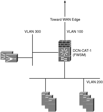
Figure 6-13 shows a sample data center topology with an FWSM deployed in the server farm aggregation layer.
Example 6-13 shows the FWSM configuration for this deployment model.
Example 6-13. FWSM Configuration with WAAS Interoperability
!
hostname FWSM
enable password 8Ry2YjIyt7RRXU24 encrypted
names
!
interface Vlan200
 nameif server
 security-level 99
 ip address 160.1.1.2 255.255.255.0
!
interface Vlan100
 nameif client
 security-level 10
 ip address 80.1.1.1 255.255.255.0
!
passwd 2KFQnbNIdI.2KYOU encrypted
ftp mode passive
access-list out2 extended permit tcp any any
access-list out1 extended permit icmp any any echo
access-list out1 extended permit tcp any any eq https
access-list out1 extended permit tcp any any eq 8443
access-list out1 extended permit tcp any any eq www
access-list out1 extended permit tcp any any eq ftp
access-list out1 extended permit tcp any any eq telnet
access-list out1 extended permit tcp any any eq 4050
access-list out1 extended permit tcp any any eq 445
access-list ftp-cap extended permit tcp any any eq ftp
!
<output omitted>
!
icmp permit any server
icmp permit any echo server
icmp permit any client
icmp permit any inside
icmp permit any echo inside
no asdm history enable
arp timeout 14400
nat (inside) 1 0.0.0.0 0.0.0.0
!
static (server,client) 80.1.1.5 150.1.1.3 netmask 255.255.255.255
access-group out1 in interface server
access-group out1 in interface client
access-group out1 in interface inside
route server 170.1.1.0 255.255.255.0 160.1.1.1 1
route server 150.1.1.0 255.255.255.0 160.1.1.1 1
route server 190.1.1.0 255.255.255.0 160.1.1.1 1
route server 80.1.1.5 255.255.255.255 160.1.1.1 1
route client 0.0.0.0 0.0.0.0 70.1.1.2 1
!
<output omitted>
!
class-map inspection_default
 match default-inspection-traffic
!
policy-map global_policy
 class inspection_default
  inspect dns maximum-length 512
  inspect ftp
  inspect h323 h225
  inspect h323 ras
  inspect rsh
  inspect smtp
  inspect sqlnet
  inspect skinny
  inspect sunrpc
  inspect xdmcp
  inspect sip
  inspect netbios
  inspect tftp
  inspect waas
  inspect icmp
  inspect http
!
service-policy global_policy global
prompt hostname context
!
Example 6-13 shows the use of the CLI command inspect waas, which enables interoperability between FWSM and WAAS. This command is available in all modes, and can be enabled per context.
Cisco PIX/ASA is also commonly used in data center environments. Like FWSM, PIX/ASA provides interoperability with WAAS beginning in software version 7.2.3. Example 6-14 shows a sample ASA configuration for providing interoperability with WAAS.
Example 6-14. PIX/ASA Configuration with WAAS Interoperability
!
hostname ASA
domain-name default.domain.invalid
enable password 8Ry2YjIyt7RRXU24 encrypted
names
!
interface GigabitEthernet0/0
 nameif inside
 security-level 100
 ip address 10.30.3.2 255.255.255.0
!
interface GigabitEthernet0/1
 nameif outside
 security-level 0
 ip address 10.30.2.3 255.255.255.0
!
interface GigabitEthernet0/2
 shutdown
 no nameif
 no security-level
 no ip address
!
interface GigabitEthernet0/3
 shutdown
 no nameif
 no security-level
 no ip address
!
interface Management0/0
 nameif management
 security-level 100
 ip address 171.68.96.120 255.255.255.0
 management-only
!
passwd 2KFQnbNIdI.2KYOU encrypted
boot system disk0:/asa722-33-k8.bin
ftp mode passive
dns server-group DefaultDNS
 domain-name default.domain.invalid
same-security-traffic permit intra-interface
access-list outside_access_in extended permit tcp 10.3.0.0 255.255.255.0 any eq https
access-list outside_access_in extended permit tcp 10.3.0.0 255.255.255.0 any eq 8443
access-list outside_access_in extended permit tcp 10.3.0.0 255.255.255.0 any eq 4050
access-list outside_access_in extended permit tcp 10.3.0.0 255.255.255.0 any eq www
access-list outside_access_in extended permit tcp host 10.0.2.4 any eq 8443
access-list inside_access_in extended permit ip any any
pager lines 24
logging enable
logging console debugging
logging asdm informational
mtu inside 1500
mtu outside 1500
mtu management 1500
no failover
icmp unreachable rate-limit 1 burst-size 1
icmp permit any inside
icmp permit any outside
asdm image disk0:/asdm-522.bin
no asdm history enable
arp timeout 14400
access-group inside_access_in in interface inside
access-group outside_access_in in interface outside
route inside 10.30.0.0 255.255.255.0 10.30.3.1 1
route inside 10.30.1.0 255.255.255.0 10.30.3.1 1
route outside 10.0.2.0 255.255.254.0 10.30.2.1 1
route outside 10.0.254.0 255.255.254.0 10.30.2.1 1
route outside 10.3.0.0 255.255.255.0 10.30.2.1 1
route outside 10.30.4.0 255.255.255.0 10.30.2.1 1
route management 0.0.0.0 0.0.0.0 171.68.96.1 1
timeout xlate 3:00:00
timeout conn 1:00:00 half-closed 0:10:00 udp 0:02:00 icmp 0:00:02
timeout sunrpc 0:10:00 h323 0:05:00 h225 1:00:00 mgcp 0:05:00 mgcp-pat 0:05:00
timeout sip 0:30:00 sip_media 0:02:00 sip-invite 0:03:00 sip-disconnect 0:02:00
timeout uauth 0:05:00 absolute
http server enable
http 0.0.0.0 0.0.0.0 management
no snmp-server location
no snmp-server contact
snmp-server enable traps snmp authentication linkup linkdown coldstart
telnet 0.0.0.0 0.0.0.0 management
telnet timeout 180
ssh scopy enable
ssh 0.0.0.0 0.0.0.0 management
ssh timeout 5
console timeout 0
!
class-map inspection_default
 match default-inspection-traffic
!
!
policy-map type inspect dns preset_dns_map

 parameters
  message-length maximum 512
policy-map global_policy
  class inspection_default
  inspect dns preset_dns_map
  inspect ftp
  inspect h323 h225
  inspect h323 ras
  inspect netbios
  inspect rsh
  inspect rtsp
  inspect skinny
  inspect esmtp
  inspect sqlnet
  inspect sunrpc
  inspect tftp
  inspect sip
  inspect xdmcp
  inspect waas
!
service-policy global_policy global
prompt hostname context
Cryptochecksum:c11b71317b49a3b461a8a3d7c19e47d1
: endThis chapter looked at the design considerations that are key to a successful WAAS deployment in the data center environment. It looked at different placement and configuration options for transparent interception, and discussed methods to scale transparent interception in the data center to hundreds or thousands of locations. Finally, this chapter looked at the configuration options available for integration between WAAS and popular Cisco firewall solutions, such as PIX/ASA and FWSM. At this point, you should have a solid understanding of the design and network integration options available with Cisco WAAS. Subsequent chapters dive into the deployment and configuration details for the different WAAS components and features.
