Previous chapters have examined a number of aspects of Cisco WAAS, ranging from network integration to management to configuring WAN optimization policies. This chapter focuses on the application acceleration components of Cisco WAAS, which help enable IT organizations to
Consolidate server and storage infrastructure
Improve performance of accessing file servers over the WAN
This chapter provides a technical overview and architectural examination of the application acceleration capabilities provided by Cisco WAAS. This chapter also provides a detailed explanation of how to configure and integrate Cisco WAAS application acceleration into a network. Along with providing an examination of how Cisco WAAS accelerates the Common Internet File System (CIFS) protocol, which is commonly used in Microsoft Windows environments for accessing files stored on file server shares, this chapter explores the details and configuration aspects of two other value-added Cisco WAAS capabilities that are directly related to application acceleration—CIFS prepositioning and disconnected mode of operation.
As discussed earlier in the book, WAN optimization refers to techniques that are employed to overcome WAN conditions, making the WAN more tolerable from an application performance perspective. Whereas WAN optimization focuses specifically on application-agnostic techniques to accomplish this lofty goal, application acceleration focuses on specific applications to improve performance. To compare and contrast, WAN optimization helps improve transport characteristics, efficiency, and performance, whereas application acceleration interacts with the application protocols themselves to overcome these limitations. Employing both of these techniques to flows traversing the WAN provides the powerful framework for ensuring that distributed users can interact with applications and collaborate with other users at performance levels similar to those enjoyed by users in the corporate campus, near the application servers themselves.
Application acceleration, especially when deployed in conjunction with WAN optimization, bridges the divide between two opposing forces. The first force is the drive to consolidate costly infrastructure for the obvious operational and capital savings (management, utilization, efficiency, data protection, recovery, hardware, and more). The challenge with consolidation is that a large portion of enterprise users would then be separated by the WAN from the resources they need to be productive, which significantly impedes performance (as discussed earlier in the book). The second force is the drive to empower remote users to increase productivity and efficiency. This force is in stark contrast to consolidation, because a foundational concept of empowering users to increase efficiency and performance is that they have application infrastructure readily available with high performance. This force tends to dictate the need to distribute application infrastructure.
Application acceleration helps bridge this divide by providing the best of both worlds—infrastructure consolidation and application acceleration—and provides the user with near-LAN response time in an environment where infrastructure is consolidated. Application acceleration, like WAN optimization, generally relies on a device deployed on both sides of a WAN link (such as a Cisco WAAS appliance or network module). These devices interact with application protocols to minimize the impact of latency, loss, and bandwidth limitations by acting as a transparent or nontransparent application layer proxy. The device closest to the user acts like the server to the user, whereas the device closest to the server acts like the user to the server. This architecture is similar to the TCP proxy architecture presented in Chapter 8, “Configuring WAN Optimization,” but rather than interacting at the transport layer, application acceleration operates at the session layer or above.
Figure 9-1 shows an example of how application acceleration in a CIFS environment looks from a user and server perspective.
As mentioned in Chapter 1, “Introduction to Cisco Wide Area Application Services (WAAS),” the CIFS acceleration architecture of Cisco WAAS uses a number of acceleration techniques, including caching, read-ahead, write-behind, pipelining, and multiplexing, to improve performance while enabling centralization.
CIFS is a stateful client/server protocol; that is, a long-lived session is established between two nodes—a client and a server. Although CIFS can be used between two servers, one will be acting as a client (mounting a shared resource and using the resource) and the other will be acting as a server (making a shared resource available). Given that CIFS is stateful, it is important to note that the client/server session may not be interrupted even in the face of a broken transport layer connection, because session management is employed above the transport layer. That is, a CIFS session remains active on the client and server until closed at the session layer, even if the underlying transport layer connection is terminated. It is also important to note that application layer acceleration for the CIFS protocol requires that Cisco WAAS see the application layer session be established, along with the establishment of the TCP connection itself.
CIFS acceleration is employed within Cisco WAAS through a dual-sided application proxy. WAAS devices deployed throughout the network perform a particular set of tasks for CIFS sessions based on the proximity to a CIFS endpoint, which determines the services that should be enabled on that WAAS device. For frame of reference, CIFS uses TCP as a transport over TCP ports 139 (CIFS over NetBIOS over TCP) or 445 (CIFS natively over TCP). Legacy Microsoft environments (for instance, Windows for Workgroups) could leverage CIFS over NetBEUI, which provided its own transport mechanism. However, these environments are rare, and it is highly unlikely that any organizations still leverage NetBEUI.
To perform CIFS acceleration, Cisco WAAS leverages three foundational components: core services, edge services, and connectivity directives. The following sections detail each of these.
Core services are the data center component of CIFS acceleration and should be enabled on WAAS devices that are deployed near file servers. In any-to-any sharing environments, where workstations are acting as servers (which is less likely), the WAAS devices deployed next to those workstations should also be configured with core services. Core services act as aggregation points for WAAS devices that are configured with edge services (discussed in the next section) and act as virtual clients to the servers that users are attempting to connect to. That is, when a user’s session is accelerated through WAAS, the edge device acts on behalf of the server to that user, and the core device acts on behalf of the client to the server that is being accessed.
Along with providing the server-side proxy functionality necessary for accelerating CIFS, the core services also provide termination of the CIFS proxy connections that are established between edge and core WAAS devices. These proxy connections, which run over TCP port 4050, are used to transport accelerated CIFS requests between WAAS devices. Two or more of these connections are established between edge and core WAAS devices, as described later in the chapter in the section “Connectivity Directives.”
WAAS devices configured with core services must be added to a “core cluster,” which is a logical grouping of adjacent WAAS devices, each of which has been configured as a core device. Edge devices are mapped to core clusters to ensure high availability.
Edge services are the remote office component of CIFS acceleration and should be enabled on WAAS devices that are deployed near users. Edge service WAAS devices establish CIFS proxy connections to a unique core service WAAS device within a configured core cluster based on the connectivity directive (discussed later in the section “Connectivity Directives”). WAAS devices configured with edge services act as “virtual servers” to the clients that are attempting to establish a session to a server in the data center.
Along with providing the user-side proxy functionality necessary for accelerating CIFS, the edge services also provide termination of the CIFS proxy connections that are established between edge and core WAAS devices. WAAS devices configured with edge services provide a client-side object cache and metadata cache for CIFS, which is independent of the DRE compression history. By keeping the application cache independent of the compression history, application performance can be maintained even in the event of massive compression history eviction, which could happen if a user were to, for instance, back up their entire home movie or music library over the WAN. Furthermore, having a separate application cache ensures that failures and cache-clearing events are isolated from one another. As an example, an application cache may be used to hold numerous gigabytes of distributed software or patches, which, if evicted, may need to be transferred over the WAN again. Keeping the cache and compression history isolated from one another provides numerous benefits in terms of operational efficiency.
In the case of both core and edge services, acceleration of the CIFS protocol is employed only when it is safe to do so. By monitoring connection state, and the interactive messages exchanged between client and server, WAAS can adjust its level of optimization to employ only those optimizations that are acceptable at that time. For instance, in the case of multiple users interacting with the same file on the server, WAAS can detect this situation and temporarily disable caching for this object. Furthermore, WAAS does not proxy (that is, respond to locally) application layer messages that could impact correctness or data integrity. As an example, a lock message, which indicates that a portion of a file needs to be locked for a particular user, is never handled locally by WAAS, and is always sent synchronously to the server for server-side processing. Safety mechanisms such as these are built into WAAS and require no user configuration.
The connectivity directive is the component that interlinks edge and core WAAS devices, and is necessary to enable CIFS acceleration. The connectivity directive definition identifies the network capacity to be consumed by CIFS acceleration, and determines the number of proxy connections that are established between edge and core devices. The proxy connections that are established are then used as the transport by which accelerated messages are exchanged between edge and core, either toward the server or toward the client. One connection is always established pass-through, and is used for messages that are synchronous and highly sensitive to latency. Such messages are generally control messages and contain little to no payload, and simply require the fastest possible delivery to their intended destination. Additional connections, which are configured to leverage the underlying WAN optimization components, are established for every 64 KB of BDP as determined by the connectivity directive definition.
Note
BDP is calculated by converting the network data rate to bytes, by dividing by 8, and then multiplying by the network latency in seconds. For example, a T1 (1.544 Mbps) equates to 193 kBps. With 100 ms of latency, the BDP of the network would be 19.3 KB. In this example, two proxy connections would be established, one as pass-through for synchronous control messages and the other for data.
As another example, assume a T3 (45 Mbps, equates to 5.625 MBps) with 200 ms of latency yields a BDP of 1.125 MB. One pass-through connection would be established for synchronous control messages, and 16 data connections would be established.
Up to 20 proxy connections can be established for each connectivity directive.
Core and edge devices can establish from 2 to 20 proxy connections between one another. This number is determined based on the bandwidth and latency parameters configured against the connectivity directive, and is discussed later in the chapter. The connectivity directive definition identifies one or more edge devices or groups, and one core cluster. In situations where a WAAS device is configured as both edge and core, a connectivity directive is required for both directions of CIFS acceleration. As an example, consider a scenario where WAAS devices are installed in two geographically separated campus locations. Each campus has users and servers, and users in each campus need to access servers locally and in the other campus. In this scenario, the WAAS devices in each location would be configured as both core and edge devices, and a connectivity directive would need to be defined for each direction.
With the exception of latency-sensitive synchronous signaling messages, all exchanges between edge and core for acceleration CIFS sessions leverage the underlying WAN optimization framework of Cisco WAAS. The Wide Area File Services (WAFS) policy determines the level of optimization applied between proxy connections established between edge and core. By leveraging the WAN optimization components of Cisco WAAS, not only are CIFS sessions accelerated, but the transfer of messages across the WAN is highly optimized. By coupling a user-side object and metadata cache (and other optimizations) with WAN optimization, the following benefits are realized:
Increase in application throughput: Higher data rates through local object delivery (full or partial) and minimized WAN bandwidth consumption (through compression and DRE).
Decrease in perceived latency: Faster delivery of partial or full objects (through user-side cache) and optimized transfer over the WAN.
Decrease in server load: Message processing by the user-side object and metadata cache when safe minimizes the number of messages that must traverse the WAN and be processed by the server, resulting in a decrease in server workload and utilization.
Figure 9-2 visualizes the application acceleration components of Cisco WAAS, and their interaction with underlying WAN optimization techniques.
This section examines the configuration and validation of all of the necessary CIFS acceleration components, including core services and clusters, edge services, connectivity directives, and the relevant application traffic policies. Configuration of CIFS acceleration must be performed from the Central Manager. Verification can be done in numerous locations, including the Central Manager, device GUI, and device CLI.
The first step in configuring CIFS acceleration is to identify which WAAS devices will be configured with core services. Any WAAS device that is deployed near file servers that will be accessed in an accelerated fashion through a distant WAAS device should be configured with core services. Configuration of core services involves two steps: defining one or more WAFS core clusters, and enabling and starting core services on the WAAS devices themselves.
A WAFS core cluster is a type of device group that identifies WAAS devices that are deployed within the same location that should act as aggregation points for WAAS devices configured with edge services performing CIFS acceleration. A WAFS core cluster should be configured for each location, and only in certain corner cases should multiple WAFS core clusters be required within a single location. Given that the vast majority of deployments do not require multiple core clusters in a given location, this text will not focus on such a deployment.
The WAFS core cluster is the entity that edge devices are mapped to through connectivity directives. When the connectivity directive information is propagated to edge WAAS devices, the information about each of the WAFS core cluster members is also sent. When the edge device receives this information, it retains it in memory to allow identification of an alternate cluster member should the member it is connected to fail. The edge device chooses the WAFS core cluster member to connect to by randomizing the list of devices contained in the cluster, and attempting connection sequentially through the list until the connection is accepted. If a connection from the edge to the core fails after it is already established, the edge assumes responsibility for attempting reconnection to a member of the WAFS core cluster. If all members of the WAFS core cluster are offline, the edge continuously attempts reconnection in 90-second intervals.
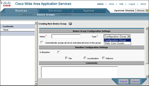
To configure the WAFS core cluster device group from the CM, choose Devices > Device Groups and click the Create New Device Group icon. Additionally, you can edit existing WAFS core cluster device groups from this page by clicking the Edit icon next to the device group entry. When you are defining or editing the device group, ensure that the Type field is set to WAFS Core Cluster.
The WAFS core cluster takes the following parameters, which you should consider prior to configuring the group:
Name: The name of the device group. Generally, it is best practice to include the name of the location where the WAAS devices are deployed, to simplify management.
File server credentials: The username and password that should be used by the core WAAS devices for preposition. Note that credentials are not required for accelerating interactive user sessions.
QoS configuration: DSCP values can be assigned to high-priority accelerated CIFS messages, which can help improve performance, assuming QoS is configured in the network to handle these messages in a high-priority manner. An explicit value can be supplied, or the core cluster can be configured to match the settings configured on the edge devices connected to it.
Members: WAAS devices that are already configured with core services can be assigned to the group.
Figure 9-3 shows the configuration page for defining or editing a WAFS core device group.
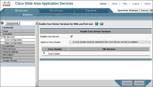
The next step is to enable core services on each of the WAAS devices that are deployed near the file servers. Enabling core services starts the upper-layer process (ULP) on the WAAS devices, allowing them to listen for incoming proxy connections from edge services running on remote WAAS devices. To enable core services on the WAAS devices through the Central Manager, choose Devices > Devices > WAE > File Services > Core Configuration. From there, check the Enable Core Server check box and choose the core cluster to assign the WAAS device to.
Figure 9-4 shows the configuration page for enabling core services on the WAAS device. Note that enabling core services on a WAAS device requires that the device be rebooted before the service can be started.
After you have enabled core services on the device, you can control and verify the status of the core services from the device GUI, which you can access in one of two ways:
From the CM homepage of the device, click the Device GUI button.
In your browser, browse directly to https://(ipaddress):8443/mgr, and then authenticate using the appropriate username and password.
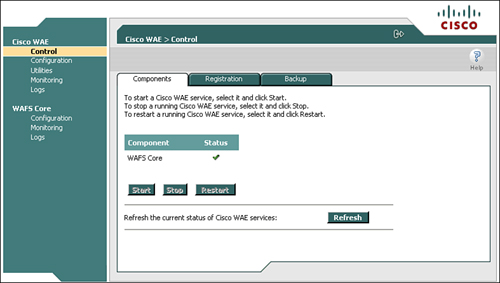
Within the device GUI, navigate to Cisco WAE > Control > Components. The configured CIFS acceleration services (WAFS Core, WAFS Edge) are listed, with either a green check mark or a red X in the Status column. Ensure that the core service is started. You can control services by clicking the service name and then clicking Start, Stop, or Restart.
Figure 9-5 shows the device GUI homepage, where you can control and verify the status of CIFS acceleration services.
The next step in configuring CIFS acceleration is to configure edge services. Edge services should be enabled on WAAS devices that are deployed near users that are accessing remote file servers, when the remote file servers have adjacent WAAS devices configured with core services. Similar to configuring core services and core clusters, edge services must be configured through the CM. Choose Devices > Devices > WAE > File Services > Edge Configuration.
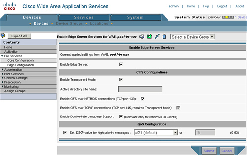
The Edge Configuration page, shown in Figure 9-6, takes the following parameters:
Enable Edge Server: Checking this box enables edge CIFS acceleration services on the WAE. Enabling edge services requires a reboot of the WAE.
Enable Transparent Mode: Ensure that this box is checked. Transparent mode allows the WAE to intercept CIFS messages destined to the origin server name for acceleration. Nontransparent mode, which requires the user map to a server name published by the WAE, is being phased out.
Active Directory Site Name: Applicable only to nontransparent mode (which should not be used), this name allows the WAE to understand where in the Active Directory topology it is deployed to ensure that, should DFS referrals be encountered, the user can be routed to the appropriate link target. Again, ensure that Enable Transparent Mode is checked, and this parameter is not required.
Enable CIFS over NetBIOS Connections: Checking this box allows the WAE to intercept CIFS requests on TCP port 139, which is used for CIFS messages transmitted over the NetBIOS session protocol. CIFS over NetBIOS is commonly used for legacy Windows releases (those released prior to Windows 2000). It is recommended that you check this box, to ensure legacy clients receive the benefits of acceleration.
Enable CIFS over TCP/IP Connections: Checking this box allows the WAE to intercept CIFS requests on TCP port 445, which is used for CIFS messages transmitted natively over TCP. CIFS over TCP/IP is commonly used for newer Windows releases (from Windows 2000 on). Ensure that this box is checked.
Enable Double-Byte Language Support: Checking this box allows the WAE to support double-byte characters, which is required for foreign language support and for optimizing Windows 98 clients. It is recommended that you check this box.
Set DSCP Value for High Priority Messages: Checking this box allows the WAE to apply a configured DSCP value to high-priority CIFS messages that must be transferred over the WAN. Check this box if you are using QoS in the network, and supply a DSCP value that represents high-priority interactive traffic that aligns with your QoS strategy.
Note
As mentioned earlier, you can configure the core service to apply a DSCP setting to high-priority CIFS messages. You can also configure the core service to use the configuration settings applied to the connected edge WAE with which it is communicating.
After you have configured edge services, you must reboot the WAE before the services can be utilized. This is due to the reprovisioning of the file system that must take place to allocate capacity for the CIFS object and metadata cache. You can reboot the system by using the reload CLI command, or by clicking the Reload WAE icon on the device homepage in the Central Manager.
Similar to core services, edge services can be verified and controlled from the device GUI. Figure 9-7 shows the device GUI with edge services enabled.
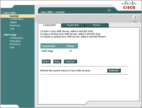
You can also use the WAE CLI to verify that the edge services are running. The command show tfo accelerators, as discussed earlier in the book, shows the status of each of the acceleration components of the WAE. In the case of edge services, a TFO accelerator named CIFS is listed. If the handling level is 100 percent, the CIFS edge services are properly configured and enabled. Example 9-1 shows the output of the show tfo accelerators command on a WAE where the edge services are functioning normally.
Example 9-1. Verifying Edge Services Status from WAE CLI
WAE# show tfo accelerators
Name: TFO                    State: Registered,  Handling Level: 100%
  Keepalive timeout: 3.0 seconds,  Session timeouts: 0,  Total timeouts: 0
  Last keepalive received 00.6 Secs ago
  Last registration occurred 48:13:14:05.4 Days:Hours:Mins:Secs ago
Name: EPM                    State: Not Registered,  Handling Level: 100%
  Keepalive timeout: 5.0 seconds,  Session timeouts: 0,  Total timeouts: 0
  Last keepalive received 48:13:14:19.0 Days:Hours:Mins:Secs ago
  Last registration occurred 48:13:14:21.0 Days:Hours:Mins:Secs ago
Name: CIFS                   State: Registered,  Handling Level: 100%
  Keepalive timeout: 4.0 seconds,  Session timeouts: 0,  Total timeouts: 0
  Last keepalive received 00.5 Secs ago
  Last registration occurred 48:13:13:09.9 Days:Hours:Mins:Secs ago
Connectivity directives interlink WAE devices configured with edge services to those that are configured with core services for the purposes of CIFS acceleration. The connectivity directive defines the configuration for the transport over which CIFS proxy connections are established between edge and core WAE devices using TCP port 4050. CIFS-related messages that are exchanged between edge and core WAEs use this transport, which includes control and data exchanges.
To configure connectivity directives from the Central Manager, choose Services > File > Connectivity and specify the following parameters:
Name: Provide a name for the connectivity directive. Connectivity directives are commonly named using a convention involving the core cluster name and the edge device or edge group name or location, such as BostonCore-SeattleEdge or simply Boston-Seattle.
Core Cluster: Specify the core cluster that should provide one end of termination for this connectivity directive. All core cluster members will participate in this connectivity directive.
File Server Settings tab: Defines how file server names are exported, which is only necessary for nontransparent CIFS deployments. Using nontransparent CIFS deployments is not recommended, so do not apply any changes to this tab.
Edge Devices or Groups: Specify which edge devices or edge device groups should provide the opposite end of termination for this connectivity directive. All items defined must be of the same type; that is, there cannot be a mix of edge devices and edge groups in the connectivity directive definition.
WAN Utilization: Defines the WAN bandwidth and latency characteristics of the link connecting the edge and core devices. This allows the edge WAE to calculate the number of proxy connections that must be established between edge and core to ensure that the link capacity can be fully leveraged.
Note
Cisco WAAS automatically detects CIFS servers and does not require that you manually define each of them. You can define CIFS servers manually (at Services > File > File Servers) if you want to, but there is no benefit in doing so. This text focuses solely on deployment scenarios where WAAS is allowed to automatically detect CIFS servers and does not cover deployment scenarios where CIFS servers are explicitly configured.
Additionally, Cisco WAAS will bypass acceleration in very low-latency environments to eliminate resource consumption. This is manifested when users connect to file servers through WAAS devices over a LAN.
Because WAN utilization is configured as part of the connectivity directive, sharing a connectivity directive across a group of edge devices is recommended only if the WAN bandwidth and latency between the core devices and all of the edge devices is very similar. The edge device calculates the BDP of the network, and determines the number of proxy connections to establish to the selected core cluster member from the connectivity directive. As described in a note earlier in the chapter, the edge can establish up to 20 proxy connections to the core for a given connectivity directive.
The proxy connections that are established between edge and core devices use the underlying WAN optimization framework provided by WAAS, including TFO. TFO helps to ensure fairness among optimized and unoptimized connections by using an adaptive congestion avoidance mechanism. The congestion avoidance mechanism in TFO aggressively increases the available window capacity in scenarios where packet loss is absent, and reverts to a less aggressive behavior that closely resembles TCP when packet loss is frequent.
This is important for ensuring that proxy connections—even in networks without QoS—do not compromise on all of the available WAN bandwidth. If the proxy connections begin consuming a significant portion of WAN bandwidth—to the point that it causes congestion—the proxy connections will be throttled due to the adaptive congestion avoidance of TFO. To summarize this concept, configuring the actual link speed and WAN latency in the connectivity directive will not cause accelerated CIFS traffic over the proxied connections from starving other accelerated or pass-through connections from being able to leverage their fair share of network capacity. In situations where the bandwidth is freely available without contention, the proxy connections will be able to leverage a generous portion of the link capacity.
After you define the connectivity directive, you can use the WAE CLI to validate the presence of proxy connections. Additionally, you can use the WAE device GUI to validate connectivity between edge and core.
Example 9-2 shows how to verify the presence of CIFS acceleration proxy connections from the WAE CLI.
Example 9-2. Verifying CIFS Acceleration Proxy Connections
WAE# show tfo connection summary server-port 4050
Optimized Connection List
Policy summary order: Our's, Peer's, Negotiated, Applied
F: Full optimization, D: DRE only, L: LZ Compression, T: TCP Optimization
Local-IP:Port         Remote-IP:Port        ConId   PeerId            Policy
10.10.100.2:13512     10.10.10.240:4050     119815  00:05:9a:3d:31:dd F,F,F,F
10.10.100.2:13513     10.10.10.240:4050     119816  00:05:9a:3d:31:dd F,F,F,F
10.10.100.2:13514     10.10.10.240:4050     119817  00:05:9a:3d:31:dd F,F,F,F
10.10.13.240:37849    10.10.10.240:4050     2       00:11:25:ac:3c:5c F,F,F,F
10.10.13.240:37850    10.10.10.240:4050     3       00:11:25:ac:3c:5c F,F,F,F
10.10.13.240:37851    10.10.10.240:4050     4       00:11:25:ac:3c:5c F,F,F,F
You can also use the WAE device GUI to validate the presence of CIFS acceleration proxy connections. On the edge WAE, choose WAFS Edge > Monitoring > Connectivity. On the core WAE, choose WAFS Core > Monitoring > Connectivity. Figure 9-8 shows an example of using the device GUI to validate connectivity between edge and core, as shown from the edge device GUI.
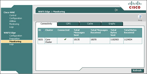
The final piece in verifying the configuration of CIFS acceleration is to examine the configuration of the CIFS acceleration traffic policies. These policies are configured by default and should require no modification. However, an examination of each of the policies is provided here to enable you to understand the reason for the policies and, if you ever need to change them, give you a reference for how to ensure they are configured correctly.
Like other application traffic policies, as discussed in Chapter 8, the CIFS acceleration policies are constructed using the ATP, and can be defined explicitly against a device or a device group. For the purposes of ensuring consistent configuration, it is recommended that these policies be configured against a device group. The CIFS acceleration policies are included in the default policy that is, by default, applied to the AllDevicesGroup.
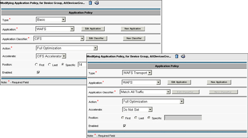
CIFS acceleration relies on two policies:
CIFS policy: A basic policy that defines the application as “WAFS” using traffic classifier CIFS, and specifies that the flow should be handled by the CIFS Accelerator. An optimization of Full Optimization is specified, in case any of the messages require transmission over the WAN.
WAFS policy: A WAFS transport policy that defines the application as “WAFS” using traffic classifier Match All Traffic, and specifies that the flow should leverage the optimization of Full Optimization.
The CIFS accelerator uses these policies individually in the following ways. The CIFS policy is used for CIFS traffic that is entering a WAE from an external client or an external server. That is, when a client issues a CIFS request, or a server issues a CIFS response, the CIFS policy is used to classify the traffic as CIFS and direct the traffic first to the CIFS acceleration service running on that particular node. If CIFS acceleration is not configured, traffic is not passed to the CIFS acceleration service and is instead passed through the WAN optimization system. As a reminder, any TCP connection passing through WAN optimization must complete automatic discovery for any policy to be applied, and CIFS is not an exception.
If the CIFS acceleration service is running and a peer of the opposite service type is connected, the traffic is fully terminated by the CIFS acceleration service. Any traffic that requires transmission over the WAN uses the CIFS proxy connections, which are internally generated by the local CIFS acceleration service (edge or core). This traffic is caught by the WAFS policy, which is configured for Full Optimization, thereby leveraging DRE, TFO, and PLZ for communications over the WAN. CIFS proxy connections that are established between edge and core populate internal filters that are applied to the WAFS policy, which allows the policy to be configured as Match All Traffic. To summarize, the WAFS policy, even though it is configured as Match All Traffic, will be applied only to CIFS proxy connections.
Figure 9-9 shows the configuration pages for the CIFS traffic policy and the WAFS traffic policy.
CIFS acceleration policies, like other application traffic policies, appear in the running-config file of the WAEs themselves. Thus, you can use the CLI to validate that the policies are configured correctly. Example 9-3 shows the output of the show running-config command with the CIFS acceleration policies displayed.
Example 9-3. Verifying CIFS Acceleration Policies
WAE# show running-config
... portions removed ...
policy-engine application
   name WAFS
   classifier CIFS
      match dst port eq 139
      match dst port eq 445
   map basic
      name WAFS classifier CIFS action optimize full accelerate CIFS-adaptor
   map adaptor WAFS transport
name WAFS All action optimize fullWith services configured, connectivity directives defined, and policies in place, WAAS can move beyond basic WAN optimization of CIFS traffic and into the realm of accelerating CIFS traffic. The difference between the two is that WAN optimization primarily minimizes bandwidth consumption for CIFS traffic, whereas acceleration of CIFS traffic mitigates latency and can tremendously improve the user experience. As discussed earlier, because CIFS is a chatty protocol, WAN optimization alone might not improve the user experience in latency-bound environments.
WAAS provides numerous facilities for verifying that CIFS acceleration is occurring. These facilities exist in the device CLI and the device GUI. An examination of these facilities is provided in this section. Before proceeding, it is important to note again that CIFS is a session-oriented protocol, and CIFS sessions tend to be very long-lived—even if the underlying transport connection is broken and reestablished. The CIFS acceleration capabilities provided in WAAS rely on the presence of two important situations before CIFS can be accelerated:
Full visibility to the establishment of the TCP connection: WAAS must see the TCP connection from the beginning in order to complete the TFO AD process described in Chapter 8.
Full visibility to the establishment of the CIFS session: WAAS must see the establishment of the CIFS session between the client and server in order to begin applying CIFS acceleration to the session.
If WAAS does not have visibility to the establishment of the TCP connection, WAE devices will be unable to automatically discover one another. In this scenario, the connection will be treated as pass-through and neither optimization nor acceleration will be applied. If WAAS does not have visibility to the establishment of the CIFS session, WAE devices will be unable to discern the state of the user to server connection, nor will WAE devices be able to discern whether or not the user has successfully authenticated, whether or not the user has become authorized, or what share or file is being used by that particular user. In this scenario, the session will be treated as pass-through by the CIFS acceleration system, even if it is optimized by the WAN optimization layer beneath it.
Put simply, if connections or user sessions were established prior to enabling CIFS acceleration, you must break these connections and reestablish them for WAAS to be able to optimize and accelerate them. Multiple means of forcing reestablishment of the CIFS session and underlying TCP connection exist, including:
Reboot the client machine
Disable and enable the client network adapter
Log out and log back into the client machine
From the server, disconnect the user session
Note
One of the biggest challenges faced by those implementing CIFS acceleration is long-lived user sessions. Be sure to pay careful attention to this seemingly trivial detail when implementing CIFS acceleration.
The following device CLI commands, executed on the edge, can help validate the presence of CIFS acceleration. You should execute these commands only after user sessions have been established through a properly configured WAAS network in which CIFS acceleration is configured correctly.
Example 9-4 shows the use of the show cifs connectivity peers command, which validates that peer devices running the opposite CIFS acceleration services are connected. This command can be executed on either edge or core devices.
Example 9-4. Verifying Presence of CIFS Peers
WAE# show cifs connectivity peers
In_1219580214_10.10.100.2
In_1003195315_10.10.13.240
Example 9-5 shows the use of the show cifs session count and show cifs session list commands, which, respectively, identify the number of accelerated CIFS sessions and identify each of the accelerated CIFS sessions. These commands can be executed from the edge only, and will return an error message if executed from the core.
Example 9-5. Verifying Accelerated CIFS Sessions
WAE# show cifs session count
1
WAE# show cifs session list
Accelerated CIFS Sessions
Client                 Server                 State    Idle(s)  Resolved
10.10.13.100:2593      10.10.10.100:445       active   38       server.peap.local
You can also use the device GUI to validate the presence of accelerated CIFS connections. From the device GUI, choose WAFS Edge > Monitoring > CIFS, and examine the field Connected Sessions Count. Figure 9-10 shows sample output from this page.
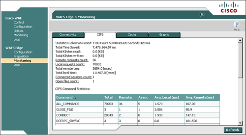
This page also provides other valuable information, including the amount of time saved by using CIFS acceleration, the number of locally served requests as compared to the number of requests that needed to traverse the WAN, and the number of files that are open through accelerated CIFS sessions.
The CIFS acceleration capability of WAAS includes a feature that allows you to schedule the delivery of selected pieces of information to a specific WAE device. This feature, called CIFS preposition (or just preposition), populates the CIFS cache in the target WAE (running edge services) and the DRE compression history. The use cases for CIFS preposition are significant, including:
Software distribution: Improve the performance and delivery of applications, software updates, and service packs to remote offices
Prime the compression history: Prepopulate the compression history on multiple devices with data that may be used interactively by users
Enable disconnected operations: Ensure specific content is available in the cache when transitioning into disconnected mode of operation (discussed later, in the section “Disconnected Mode of Operation”
Ensure highest performance for first open: Prepopulating data to the edge cache, which also populates the compression history, improves the performance for the first user accessing the content
CIFS preposition is a component of CIFS acceleration. Thus, CIFS acceleration must be configured and operational before preposition can be configured. Preposition is configured from the Central Manager and cannot be configured from the CLI. Architecturally, preposition is a capability that leverages the following pieces in the manner described:
Central Manager: Used to define the preposition task, origin server, destination (WAEs running edge services), job details, and schedule
Core WAE: Fetches a manifest (list of contents) from the origin server based on the job configuration and sends that manifest to the edge. The Edge WAE then proactively fetches content that is new or has changed based on the status of the edge cache
Edge WAE: Receives the manifest from the core WAE, and then begins requesting objects from the core based on the difference between the current cache state and manifest that was received from the core
In essence, the core acts as a “staging area,” because it is unaware of the status of the edge cache. The core, once it receives the manifest from the origin server (based on the job configuration), passes the manifest to the edge. Then, the core begins fetching files from the origin server based on the manifest. These files are then stored in a temporary staging area, which is ~1 GB in capacity. As the edge fetches files, they are removed from the staging area and the core continues to fetch additional files from the origin server. If the staging area becomes full of files, and the edge requests a file that is not in the staging area, the core will know that the edge does not need any of the files found in the staging area. In such a case, the core will empty its staging area and begin fetching files from the origin server starting with the file requested by the edge. Because the core and edge are working from the same manifest, the core can adapt and evict files from the staging area based on the requests coming from the edge.
Preposition tasks have a number of configurable parameters that allow you to specify content, origin server, size parameters, and time parameters. For instance, you can specify that a preposition job should run for no more than 1 hour, and copy all *.msi files that are at least 1 MB from a particular server to all of the edge WAEs. The parameters that you can configure on a preposition task include:
Name: Name of the preposition task. It is recommended that the type of content being prepositioned be referenced in the name (for instance, InstallerFiles or ServicePacks).
Status: A preposition task can either be “enabled” or “disabled.”
File Server: Prepositioning requires that the origin server be defined under the System > File > File Servers tab. This is the origin server that the content will be fetched from, as well as the root share, directories, and filename patterns.
Cache Parameters: Specify the percentage of cache capacity that can be consumed before the edge is instructed to stop fetching new files. This allows you to impose a capacity limit around the preposition task itself.
File Parameters: Specify the minimum file size, maximum file size, and type of preposition task (all files, changed since last preposition, or changed in the last specified interval).
Edge Devices: Defines the target devices or device groups that should be populated with the content referenced in the task. Note that devices or device groups can be defined.
Schedule: Defines when the preposition job should run, including now (immediate), daily (including a start time), date (specify a date), weekly (specify a day of week), monthly (specify one or more days of the month), or monthly weekdays (specify, for instance, the third Sunday of each week).
Figure 9-11 shows the architecture of preposition, along with the interaction of the edge, core, and origin server.
Note
CIFS preposition uses the underlying CIFS proxy connections for transfer, which leverage DRE, TFO, and persistent LZ. Files transferred through preposition will also populate the DRE compression history, which can provide substantial performance improvement if the data is written back by a remote user to a server in the data center.
The first step in configuring CIFS preposition is to define the origin server from which you wish to fetch content. In the Central Manager, choose Services > File > File Servers, click the Create New File Server icon, and then define the following parameters (see Figure 9-12):
File Server Name: Supply either the NetBIOS name, fully qualified domain name (FQDN), or IP address of the file server that you wish to distribute content from.
Allow Access on WAN Failure: This item is used by disconnected mode of operation, discussed in the next section. Check this box if you are using disconnected mode of operation.

Then, click Assign Core Clusters in the left to specify a core cluster that is near the file server. One member of the core cluster will be responsible for fetching files and acting as a staging area for the content during the execution of the preposition task.
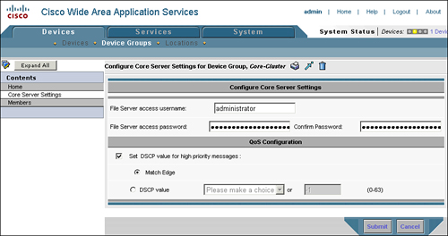
It is important to note that the core cluster you select should be configured with the appropriate credentials for accessing the file server. To configure the credentials for a core cluster, choose Devices > Device Groups > <devicegroupname> > Core Server Settings. The credentials configured on this page are used only during preposition tasks, and are not required for accelerating interactive CIFS sessions from a user to a server.
Figure 9-13 shows the Central Manager configuration page for defining the credentials used by a core cluster when connecting to a file server for the purposes of prepositioning. The credentials supplied need only read access to the share and its contents; it is not necessary to supply read/write access. You should always follow the principle of least privilege when distributing permissions to network devices.
The next step in configuring preposition is to create the preposition job. Before continuing, be sure you have a solid understanding of what it is you want to preposition, where you want to preposition it to, and where the content should be fetched from. A good list to examine before defining a preposition job is the second list in the previous section (“CIFS Preposition Architecture”), which outlines the configuration items associated with a preposition job.
To configure a new preposition job, choose Services > File > Preposition, click the Create New Preposition Directive icon, and supply the GUI with the name, status, file server, cache parameters, and file parameters. The preposition job definition page is shown in Figure 9-14.
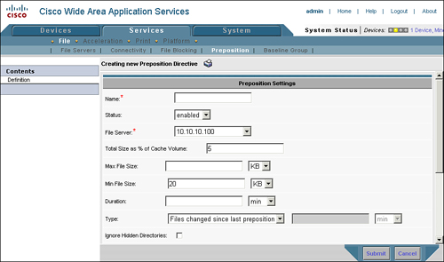
Of particular interest on the preposition job configuration page is the Browse button that appears after you have specified the file server. Clicking this button enables you to interactively select shares and folders contained within those shares in a similar manner to using a file browser. Using this tool simplifies the definition of the source location that content should be distributed from.
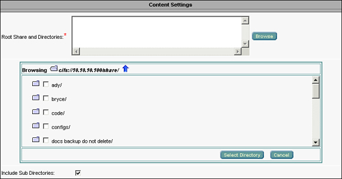
Figure 9-15 shows an example of the interactive browser provided within the preposition job configuration page. When navigating the preposition browser, be sure not to use the browser’s Back button. Instead, use the navigation options such as the “move up to parent folder” icon, which is represented as a blue arrow.
After you have specified the initial preposition job parameters, click the Submit button to save the configuration. Upon saving the parameters, the table of contents in the left pane will adjust to show the remainder of the preposition configuration items, which include edge device/group assignment and schedule. Similar to other configuration items, edge devices and edge groups can be configured by simply clicking the blue X next to the device or group name, and this configuration can be saved by clicking Submit.
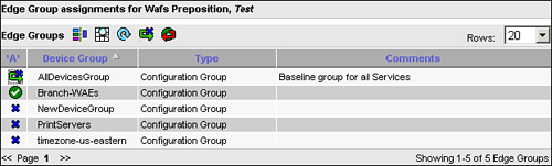
Figure 9-16 shows an example of the appearance of the edge group configuration page. Notice that the Branch-WAEs group is already configured as a target for this preposition job, and the AllDevicesGroup has been selected but the update has not yet been submitted. It should be noted that the configuration page for selecting one or more edge devices individually is very similar, but shows the list of unique devices as opposed to the list of groups.
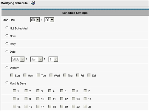
After selecting the target devices or device groups, click Schedule to set the schedule for the preposition job. Preposition jobs can be assigned one of the following schedules:
Not Scheduled: The preposition job will not run. The job is effectively disabled when it is not scheduled.
Now: The preposition job will run immediately. The Central Manager will distribute the job details to the appropriate devices on the next LCM cycle interaction with those devices.
Daily: The preposition job will run every day. The Start Time parameter can be defined to specify when the job should start. The job will run through the duration configured against the preposition job according to its definition.
Date: The preposition job will run once on the date specified. The Start Time parameter can be defined to specify when the job should start. The job will run through the duration configured against the preposition job according to its definition.
Weekly: The preposition job will run weekly on the days of the week specified (Sunday through Saturday). The Start Time parameter can be defined.
Monthly Days: The preposition job will run monthly on the individual days selected (1 through 31). The Start Time parameter can be defined. If the defined days do not exist in a particular month (for instance, if you check 30 and enter the month of February), the job will not run. As such, it is best to configure preposition jobs to run earlier in the month as opposed to later.
Monthly Weekdays: The preposition job will run upon encountering the specific occurrence of a particular weekday. For instance, the third Thursday of every month. The Start Time parameter can be defined.
Figure 9-17 shows an example of the configuration page for defining the schedule of a preposition job.
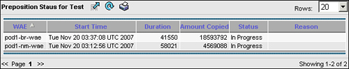
After you have defined the preposition job, it appears in the Preposition Status window. This window shows the target edge devices and groups, and identifies the start time, duration, amount copied, status, and any reason associated with the job status.
As mentioned in the previous section, you can examine the status of a preposition job on the Preposition Status page in the Central Manager (choose Services > File > Preposition > Preposition Job > Preposition Status). Figure 9-18 shows an example of the preposition status.
The Central Manager is not the only place that you can check the preposition status. You can examine the device GUI for the edge devices to see the status and statistics for each of the preposition jobs. Open the device GUI for the edge and choose WAFS Edge > Preposition to see a tabular view containing the following information:
Job ID: A unique identifier, created by WAAS, that identifies the preposition job
Description: The name of the preposition job
Root Directory: Defines the listing of servers, shares, and folders that are included in the preposition job
Schedule: Defines the schedule assigned to the preposition job
Started: If the job is running, defines when the job started; otherwise, identifies when the last job started
Duration: If the job is currently active, lists the amount of time the job has been running; otherwise, lists the length of time the last job ran for
Status: Lists the status of the preposition job
Termination Reason: Lists the reason why the last job terminated
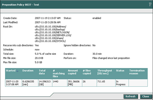
Clicking an individual job and then clicking View provides you with a more detailed view of the preposition job. Clicking an individual job and then clicking Terminate allows you to stop the currently running job. When examining the detailed statistics of a preposition job, you are provided with all of the configuration data associated with the preposition job, and additional data as follows:
Total Data: The capacity consumed by the files identified in the manifest as per the preposition job configuration.
Number of Matching Files: The number of files identified in the manifest as per the preposition job configuration.
Amount Copied: The amount of data that has been copied up to this point as a result of running the preposition job.
Number of Files Copied: The number of files copied up to this point as a result of running the preposition job.
Throughput: The average rate of transmission of the preposition job. Note that throughput is listed in kBps, as opposed to kbps or Mbps.
Status: The status of the current job.
Termination Reason: If the job terminated, the reason why the job terminated.
Figure 9-19 shows the status page from a preposition job as seen from the device GUI of an edge device.
Although the device CLI does not expose information about specific preposition jobs that are running, it does provide a series of helpful tools that can expose statistics about the edge cache. For instance, you can examine the disk capacity consumed by the CIFS cache from the device CLI, and identify the number of objects stored in the CIFS cache. During a preposition job, if there are any changed files or new files, these counters will increment as the files are fetched. Neither the device CLI nor the device GUI exposes the list of files that are cached in the device itself. This is done to ensure the security of the contents of the WAE disk contents.
Example 9-6 shows the output of the commands that can be executed from the WAE CLI to examine cache disk capacity consumption and the number of cached objects.
The last capability of the CIFS acceleration component of Cisco WAAS covered in this chapter is disconnected mode of operation. Disconnected mode of operation, also called disconnected mode, is a caching model that, when implemented on the edge, allows the edge WAE to provide read-only service to remote users in the event of a network or service disconnection. Disconnected mode is a configurable parameter and is applied to a server that has been defined in the Central Manager. When this setting is applied (by checking the Allow Access on WAN Failure check box, shown earlier in Figure 9-12), the edge device becomes more aggressive in caching contents and metadata requested from this server. This behavior can be characterized as follows:
More aggressive read-ahead requests: The edge device will try to cache larger portions of the requested objects to improve probability that an object is available in the event of a WAN disconnection.
Directory and metadata caching: The edge device normally caches directory metadata for a short period of time (5 seconds) to optimize interactive user operations such as folder browsing. With disconnected mode, the edge device caches directory metadata persistently, until evicted due to change or capacity constraints.
Access control entry caching: The edge device, which normally does not cache access control information, will begin caching this data, and use it for determining access control during periods of disconnection. This data is not used unless the network is in a disconnected state.
It is recommended that disconnected mode be used in conjunction with CIFS preposition (discussed in the previous section) to ensure that contents of interest are available during periods of network disconnection. For instance, if the server being made available during periods of network disconnection is used to provide application installation files, hotfixes, or other critical infrastructure software, it is recommended that one or more preposition jobs be configured to run periodically to ensure that these objects are cached. Using preposition helps to improve the likelihood that the objects are available during periods of disconnection. In reality, it is not the server that needs to be available during periods of disconnection, but rather the information stored on that server.
Disconnected mode of operation requires that a local Active Directory domain controller be reachable on the network to successfully transition into disconnected mode. That is, if the network becomes severed, a domain controller must be reachable to authenticate users. For remote offices in which a domain controller is installed, or in cases where the connection to the data center is severed but a domain controller can be reached elsewhere, the edge device can transition into disconnected mode without an issue. Given that the edge device never locally authenticates a user (it relies on the authentication provided within CIFS at the beginning of each session), the edge device cannot provide value in disconnected mode if a domain controller is not available to authenticate users.
Disconnected mode requires that edge devices be joined to the Active Directory domain. By joining the edge device into the domain, it can then forward authentication requests to a domain controller for the purpose of authenticating users. If a user is authenticated successfully by a domain controller (that is, the user’s identity is verified through the request that was forwarded by the edge device to the domain controller), the edge device can then authorize the user based on cached access control entries for the object in question. If the edge device cannot reach a domain controller, or does not have cached the access control entry information about the object being requested, then the object will not be made available.
Domain integration can be configured from the Central Manager, device GUI, or device CLI. For purposes of ensuring simplicity, this chapter covers integration of the WAE into the domain using the Central Manager or the device CLI.
The first step in ensuring integration into the domain is to set the correct time zone and time on each WAE. Domain integration requires that each domain member, including WAEs, be no more than 5 minutes askew from the relative time on the domain controller. That is, the time difference on the WAE, after accounting for time zone differences, must be within 5 minutes of the relative time on the domain controller.
The simplest way to align time on the WAE device with the domain is to first set the time zone on each WAE and then configure each WAE to use a Network Time Protocol (NTP) server. Although this can be easily accomplished through the device CLI, as you can see in Example 9-7, recommended practice dictates that you create unique device groups, where each device group represents a separate time zone. After you add the appropriate WAE devices into each timezone-based device group, you can apply the NTP server settings to the device group.
Example 9-7. Configuring Time Zone and Time on Device CLI
WAE# show clock
Local time: Wed Nov 21 23:09:49 UTC 2007
WAE# clock set 23:49:00 21 Nov 2007
WAE# configure
WAE(config)# clock timezone PST8PDT -8 0
WAE(config)# ntp server 10.10.10.100
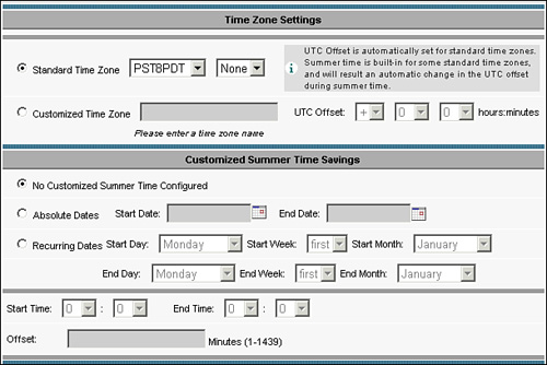
Figure 9-20 shows how to configure NTP server settings from the Central Manager against a device group. To reach this page, choose Devices > Device Groups > Device Group > General Settings > Miscellaneous > Date/Time > Time Zone.
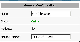
Once the system time between the WAE and the domain has been aligned, and is within a 5-minute skew, the next step is to ensure each WAE device has an assigned NetBIOS name. You can configure the NetBIOS name from either the device CLI or the Central Manager. Example 9-8 shows how to configure the WAE NetBIOS name from the device CLI.
Example 9-8. Configuring WAE NetBIOS Name from Device CLI
WAE# configure
WAE(config)# windows-domain netbios-name POD1-BR-WAE
Figure 9-21 shows how to configure the WAE NetBIOS name from the Central Manager using the activation page found at Devices > Devices > WAE Device Name > Activation. Note that device groups cannot be used for configuring NetBIOS names, because each NetBIOS name within the domain must be unique. Thus, a NetBIOS name cannot be shared among WAEs; each must be unique.
The next step in domain integration is to define domain-related parameters within each WAE device or against a common device group. If WAEs are to be registered against multiple autonomous domains, it is recommended that you either apply the domain settings individually to each WAE or configure separate device groups to represent each possible configuration. If WAEs are to be registered against a single domain using common, shared parameters, it is recommended that you apply these settings against the AllDevicesGroup device group. Domain-related parameters include the following, which much be configured:
Domain Name Server (DNS) addresses: Used for name resolution.
Windows Internet Name Service (WINS) Server addresses: Used if DNS is not available. WINS may not be necessary, as many customers have migrated to DNS-based Active Directory and phased WINS out of their environments.
Domain Name: The domain name that the WAE will be integrated into.
Domain Controller IP or Fully Qualified Domain Name (FQDN): The IP address or FQDN on the domain controller that the WAE should attempt to register itself with.
Authentication Protocol Specific Options: Parameters related to the authentication protocol being used. Because Kerberos is the most commonly encountered, this chapter focuses on Kerberos specifically. Note that NTLMv1 and v2 are also supported.
Example 9-9 shows how to configure the DNS and WINS server entries from the device CLI.
Example 9-9. Configuring DNS and WINS Settings from Device CLI
WAE# configure
WAE(config)# ip domain-name company.com
WAE(config)# ip name-server 10.10.10.100
WAE(config)# windows-domain wins-server 10.10.10.100
WAE(config)# windows-domain workgroup "PEAP"
You can also configure the DNS and WINS settings from the Central Manager using the following pages, which you access from the device homepage:
Domain Name: General Settings > Network > DNS
DNS Server Addresses: General Settings > Network > DNS
Windows Domain Name: General Settings > Network > Windows Name Services
WINS Server Addresses: General Settings > Network > Windows Name Services
The next step is to define the domain controller either by its IP address or its FQDN. Example 9-10 shows how to define the domain controller in the device CLI. Kerberos is shown in this example.
Example 9-10. Defining Domain Controller Using Device CLI
WAE# configure
WAE(config)# kerberos local-realm COMPANY.COM
WAE(config)# kerberos realm company.com COMPANY.COM
WAE(config)# kerberos server COMPANY.COM 10.10.10.100 port 88
WAE(config)# windows-domain password-server "company.com"
WAE(config)# windows-domain security ADS
WAE(config)# windows-domain realm "COMPANY.COM"
From the Central Manager GUI, you can configure these same settings by choosing Devices > Devices > WAE Device Name > General Settings > Authentication > Windows Domain. If the WAE or WAEs are to be integrated into a Windows domain where Windows 2000 Server Service Pack 4 or newer or Windows 2003 Server Service Pack 1 or newer is being used, it is recommended that you also add the command shown in Example 9-11.
After you have applied the configuration, the next step is to instruct the WAE to join the Windows domain, which you can do from either the device CLI or the Central Manager. The Central Manager provides a status screen that automates verification of all of the domain integration components. The CLI, on the other hand, does not, but commands are available to validate successful integration and, more importantly, why an attempt to join the Windows domain failed.
To join a Windows domain using Kerberos from the device CLI, execute the command shown in Example 9-12. When executing this command, be sure to include the quotes, but do not use the brackets, which are only there to show you the value that needs to be supplied. It is important to note that the credentials supplied (username and password) must have the appropriate permissions within the Windows domain to add new computer accounts. It is generally recommended that the domain administrator credentials be used.
Example 9-12. Joining a Windows Domain from the Device CLI
WAE# windows-domain diag net "ads join -S servername -U username%password"
Using short domain name -- PEAP
Joined 'POD1-BR-WAE' to realm 'PEAP.LOCAL'
If you encounter an issue, use the following commands to troubleshoot issues with joining the domain:
To check the trust secret between the Windows domain and the WAE, use windows-domain diagnostics wbinfo –t.
To check the domain sequence number, use windows-domain diagnostics wbinfo --sequence.
To verify accessibility of domain information, use windows-domain diagnostics wbinfo –D domainname.
Joining the Windows domain from the Central Manager can be done from a single page in the GUI, and thus it is the recommended interface for this task. To join the WAE into the Windows domain, ensure that the settings defined in the last section are configured, and then choose Devices > Devices > WAE Device Name > Authentication > Windows Domain. All relevant parameters configured in the previous section should appear in the appropriate location. Near the bottom of the page, as shown in Figure 9-22, are fields that allow you to specify the domain administrator username and domain administrator password. It is again important to note that the credentials supplied here must have the appropriate permissions within the domain to join a new computer into the domain.
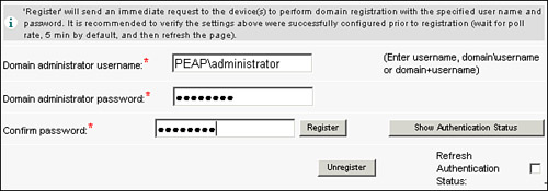
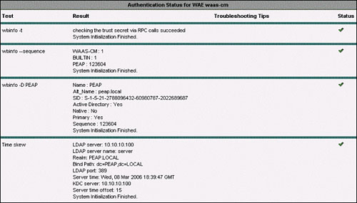
After supplying the credentials, click the Register button. This causes the WAE to attempt to join the Windows domain. Then, click Show Authentication Status to view the status of integration. Figure 9-23 shows the Authentication Status window. If there is an issue with joining the WAE into the domain, this window provides troubleshooting tips on what is not configured correctly or what failed when attempting to join the domain.
Configuring disconnected mode of operation is simple and straightforward, once the WAE has been successfully joined into the Windows domain. To configure disconnected mode of operation, simply check the Allow Access on WAN Failure box on the configuration page for the file server. (Refer to Figure 9-12.) Before taking a closer examination of the disconnected mode of operation, it is necessary to first understand the two types of disconnected operation supported by WAAS.
Disconnections, as related to CIFS acceleration, are categorized in one of two ways: intermittent disconnection and prolonged disconnection. Intermittent disconnection is defined as a period of up to 90 seconds during which the connectivity between an edge device and a core device is severed. During this period of time, the user might not notice a disturbance, because WAAS masks intermittent disconnection by temporarily queuing requests until the connection between edge and core is restored. If the client submits an interactive request, which demands a server response (such as a file save operation), the operation will hang and the application may become temporarily unresponsive until either connectivity is either restored or the system enters into prolonged disconnected mode. During this initial 90-second period, the edge WAE begins testing connectivity to additional devices that are members of the peer core cluster. If a new peer is identified, all CIFS sessions are destroyed, causing the client redirector to automatically reestablish the session. From a user perspective, this is disruptive only in cases where interactive requests are present.
Prolonged disconnected mode is any disconnection scenario that extends beyond the 90-second window. In this mode, the edge device destroys any active CIFS sessions, which forces the sessions to be re-created. At this point, the edge device begins publishing the name of the disconnected server on the network, and intercepts all requests going to that server to be handled locally. When the new CIFS session requests inevitably come in from the users that were active during the disconnection (or new user sessions), the WAE forwards the authentication request to the domain controller. If the domain controller deems the user authentic, the WAE begins to provide that user access to cached metadata and data based on the cached authorization information (access control entries). If a file is not fully cached, or certain metadata is not cached, the file is not made available to the user even if they are authorized, because the WAE does not have the information in the first place.
If the connection between the edge and core is restored, which is checked every 90 seconds once prolonged disconnected mode has been entered, CIFS sessions are once again torn down. New sessions, which are typically re-created automatically by the user, will be accelerated as normal.
Figure 9-24 shows the transition into prolonged disconnected mode of operation.
Cisco WAAS provides a powerful suite of CIFS acceleration components that complement the underlying WAN optimization framework to help enable infrastructure consolidation and improve the user experience. CIFS acceleration couples a number of application layer optimization techniques, including edge-side caching, multiplexing, and read-ahead to dramatically improve CIFS throughput and response times, thereby providing remote users with the impression that they are working with local servers. CIFS acceleration depends upon the configuration of the edge service, core service, core cluster, and connectivity directives, each of which plays a vital role in improving performance and availability. Additionally, WAAS provides value-added features for CIFS acceleration such as preposition and disconnected mode of operation. Preposition improves probability that a set of files will be cached and data from those files will be present in the compression history, which helps to improve the performance for the first user access to the object. By using preposition, organizations can confidently consolidate additional infrastructure components such as software distribution servers while continuing to provide similar levels of performance and service. With disconnected mode of operation, organizations can provide nearly uninterrupted read-only access to cached contents if a network disconnection event occurs.