
MDSE Use Cases
The first and most known application scenario for MDSE is definitely the one of software development automation (typically known as model-driven development (MDD)) where model-driven techniques are consistently employed with the goal of automating as much as possible the software lifecycle from the requirements down to the deployed application. However, the full spectrum of possible applications for MDSE spans a much wider set of scenarios; MDD is just the tip of the MDSE iceberg (as shown in Figure 3.1).
In this sense, the acronym MD(S)E can also be read as Model-Driven Everything, that is the MDSE philosophy can be applied to any software engineering task. This chapter will focus on three main application scenarios that illustrate how the benefits of MDSE can apply to different needs. Apart from the software development scenario, we will describe the application of MDSE to the reverse engineering and software modernization field and to the tool/systems’ interoperability problem.
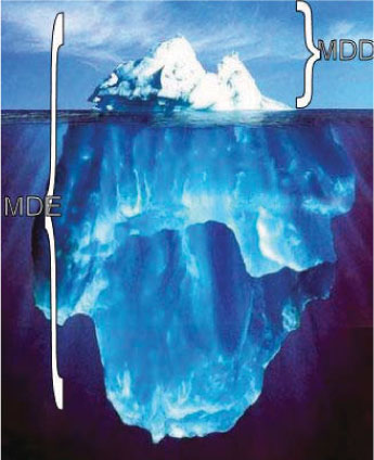
Figure 3.1: MDD is just the most visible side of MDSE.
3.1 AUTOMATING SOFTWARE DEVELOPMENT
Software development automation consists of starting from a high level (or early) representation of the desired software features and deriving a running application out of it, possibly through a set of intermediate steps to enable some degree of user interaction with the generation process.
Typically, when following an MDSE approach, the running application can be obtained through one or more model transformations that subsequently produce a more and more refined version of the software description, until an executable version of it is reached. A usual MDSE-based development process is illustrated in Figure 3.2. In each phase, models are (semi)automatically generated using model-to-model transformations taking as input the models obtained in the previous phase (and manually completed/refined when necessary). In the last step, the final code is generated by means of a model-to-text transformation from the design models.1

Figure 3.2: A typical MDSE-based software development process.
In fact,Figure 3.2 highlights one of the main advantages of model-driven approaches: bridging the communication gap between requirements/analysis and implementation. At the organization level, this translates to bridging the gap between business needs and IT realization or support. This is a major problem in a number of enterprises, and models have proven to be a valid solution as a lingua franca among actors from business and IT divisions.
There are other benefits of bringing MDSE into the development process. To mention some of them, models capture and organize the understanding of the system in a way that facilitates the discussion among team members (and eases the integration of new ones), are well suited for documentation, permit earlier exploration of design alternatives and the early evaluation of the system adequacy, increase the decomposition and modularization of the system, and improve the reuse of parts of the system in new projects and the system’ evolution and maintenance (e.g., by facilitating tracing back the code to the original requirements). Overall, the most direct benefits of MDE can be summarized as: increase of communication effectiveness between the stakeholders and increase in the productivity of the development team thanks to the (partial) automation of the development process. As a side effect, this automation reduces also the number of defects in the final code that could be inadvertently introduced by the developers.
In order to be able to generate a running system from the models, they must be executable.2 An executable model is a model complete enough to be executable. From a theoretical point of view, a model is executable when its operational semantics are fully specified. In practice, the executability of a model may depend more on the adopted execution engine than on the model itself. On the one hand, we may find some models which are not entirely specified but that can be executed by some advanced tools that are able to “fill the gaps” and execute them; on the other hand, we may have very complex and complete models that cannot be executed because an appropriate execution engine is missing. For instance (Figure 3.3), given a simple class diagram specifying only the static information of a domain, a trivial code-generator will only be able to generate the skeletons of the corresponding (Java) classes while a more complex one would be able to infer most of the system behavior out of it. As an example, this advanced generator could assume that for each class in the diagram the system will need to offer all typical CRUD (create/read/update/delete) operations and thus, it could directly decide to create all the forms and pages implementing these operations3 (in fact, studies like [3] show that the CRUD operation account for a staggering 80% of the overall software functionality in typical data-intensive applications so this advanced code-generator could save a lot of development time from a minimal system specification).
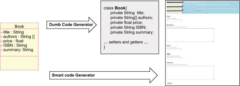
Figure 3.3: Code-generation example.
The most well-known family of executable models are those based on the UML language, generically referred as executable UML.4 Executable UML models make extensive use of an action language (kind of imperative pseudocode) to precisely define the behavior of all class methods, state transitions, etc. The OMG itself has recently standardized this notion of executable UML models. In particular, the OMG has standardized the semantics of a Foundational Subset for Executable UML Models (fUML) that suffices to model software specifications in a way that makes them suitable to be the input of an automated software development process. The adopted action language for fUML is known as the Action Language for fUML, or Alf.5 Alf is basically a textual notation for UML behaviors that can be attached to a UML model at any place a fUML behavior can be. Syntactically, Alf looks at first much like a typical C/C++/Java legacy language, which softens its learning curve.
Code-generation and model-interpretation are then two different alternative strategies to “implement” execution tools and thus make executable models actually execute.
3.1.1 CODEGENERATION
Code-generation aims at generating running code from a higher level model in order to create a working application, very much like compilers are able to produce executable binary files from source code. In this sense, code-generators are also sometimes referred to as model compilers.
This generation is usually done by means of a rule-based template engine, i.e., the code generator consists in a set of templates with placeholders that once applied (instantiated) on the elements in the model, produce the code.
Once the code is generated, common IDE tools can be used to refine the source code produced during the generation (if necessary), compile it, and finally deploy it. As depicted in Figure 3.4, the single goal of a code-generation process is to produce a set of source files from a set of models. All other activities around these files are performed using the same tools you would use to manipulate manually written code.
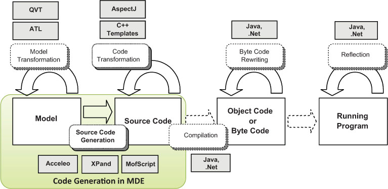
Figure 3.4: Scope of MDSE code-generation (based on [64]).
Obviously, by “source code” we do not restrict ourselves to programming languages. By means of code-generation we can transform many kinds of models to many types of software artifacts (test cases, make files, documentation, configuration files, etc).
Partial vs. Full Generation
When the input models are not complete and the code-generator is not smart enough to derive or guess the missing information, we can still benefit from a code-generation approach by creating a partial implementation of the system. Nevertheless, partial code-generation must be approached with caution. Partial generation means that programmers will need to complete the code manually to obtain a fully functional system. This leads to a situation where no single source of information exists: both the models and the code contain important information that may not be replicated in the other artifact, but at the same time some pieces of information appear in both places (e.g., the parts of the model that have been directly translated into the code). Having the same information in two places (code and models) is a recipe for trouble.
Strategies to maximize the benefit of partial code-generation include:
• defining protected areas in the code, which are the ones to be manually edited by the developer. Thanks to this, a code-generation tool can still regenerate the code with the assurance that the manually added code excerpts will be preserved;
• using round-trip engineering tool, so that changes on the code are, when possible, immediately reflected back to the model to keep both in sync;
• focusing on complete generation of parts of the system more than on a partial generation of the full system. For instance it is better to be able to say that the code-generator creates the full database implementation of the system even if no generation is done on the business logic part than having a code-generator that produces a little bit of both. We can regard the generation approach as full generation for some parts of the system avoiding the above risks for those parts.
Both in full and partial generation scenarios, one objective to keep in mind is to try to generate the smallest possible amount of code to achieve the desired functionality. An effective code-generation strategy should rely on all kinds of existing frameworks, APIs, components, or libraries in order to minimize the amount of actually generated code.
Advantages of Code Generation
There are several advantages that can be mentioned for the code-generation approach.
• It protects the intellectual property of the modeler, as it allows the generation of the running application for a specific client, without sharing the conceptualization and design, which is the actual added value of the work and which can be reused or evolved in the future for other projects. Customers are starting the request the source code of the applications they pay for but so far there is no agreement regarding whether the models should be delivered as well.
• The generated implementation is model- and process-agnostic, and therefore easier to understand: the generated code is produced in a standard programming language that any developer can understand.
• Code-generation allows customers to choose their runtime environment. This implies that the customer can avoid any risk of vendor lock-in with respect to the MDSE technology that is used. Since standard code is produced, customers can even opt for abandoning the MDSE approach in the future.
• It can target a specific architecture based on the needs or legacy solution that the customer already has in house. The generated code can precisely follow the guidelines of the customer and can provide better integration with other IT components in the organization. In a sense, code-generation grants two degrees of freedom instead of one: the model and the generator. Each of them can be tailored to the needs of the customer.
• Flexibility in the deployment of the generated code facilitates customers being compliant to their IT architecture policies and to other rules, also imposed by national or local laws (e.g., in terms of security, privacy, reliability, fault-tolerance, etc.) by exploiting the capabilities of a standard execution environment, without having to rely on a proprietary solution.
• Code-generation allows reusing existing programming artifacts. In particular, existing pieces of code can be generalized and used as templates for code-generation of the new parts of the software. If the code generator is flexible enough, it can be iteratively extended to generate more or richer pieces of code.
• A code generator is usually easier to maintain, debug, and track because it typically consists of rule-based transformations, while an interpreter has a generic and complex behavior to cover all the possible execution cases.
• Possibility of following a partial generation approach.
• In general, a generated application performs better in terms of execution speed with respect to a corresponding interpreted version.
Code-generation is not free from a few drawbacks (c.f. the benefits of the model interpretation alternative as discussed in the next section). One of the big hurdles in adopting code-generation techniques is the fact that the produced code does not look “familiar” to the developers. Even if it behaves exactly as expected and it is written in the programming language of choice, it could be very different from the code that actual programmers would write and this makes them reluctant to accept it (for instance, they may not feel confident to be able to tune it or evolve it if needed in the future). In this sense, it could be useful to define a Turing test for code-generation tools. Similar to the classic Turing test for AI,6 the Turing test for code-generation tools reads as follows.
A human judge examines the code generated by one programmer and one code-generation tool for the same formal specification. If the judge cannot reliably tell the tool from the human, the tool is said to have passed the test.
Tools passing the test would have proved they can generate code comparable to that of humans and should be acceptable to them.
The chances of passing the Turing test for code-generation may be increased by building the code generation templates starting from existing code manually written by the developers (generalizing and abstracting the templates from this code). Thus, when running these templates, they should produce code which looks more familiar to the developers.
3.1.2 MODEL INTERPRETATION
Model interpretation does not generate code from a model to create a working software application. Instead, a generic engine is implemented, which parses and executes the model on the fly, with an interpretation approach (exactly as interpreters do for interpreted programming languages).
Model interpretation is characterized by the following properties and advantages.
• It enables faster changes in the model because it does not require any explicit code-generation step. This can lead to a significant shortening of the turnaround time in incremental development approaches, as the model can be run and modified on the fly.
• It even allows changing the model at runtime without stopping the running application, as the interpreter would continue the execution by parsing the new version of the model.7
• In principle, it enables the portability of the applications because it is possible to create an interpreter which is available on multiple platforms (e.g., multiple operating systems, cloud platforms, or technologies). The interpreter basically realizes an agnostic virtual environment where a modeled application can run, exactly in the same way an interpreter works on interpreted programming languages. To achieve the same with code-generation, one should generate interpreted code, for which interpreters are available for different platforms.
• In case of model interpretation you don’t need (and you cannot) delve into the source code of the application anymore, simply because such a concept does not exist anymore (though some tools still allow you to add custom behavior as black-box components to be “interpreted” with the model depending on certain conditions). In a sense, one could say that the model is the code, because the former actually replaces in all senses the latter.
• It makes possible the empowerment or modification of the behavior of the running application by updating the interpreter and still keeping the same models (the same can be achieved in case of code-generation by updating the generator but then the code needs to be regenerated, compiled, and deployed again).
• It provides a higher level of abstraction (implemented by the interpreter) upon the system, according to the Platform-as-a-Service (PaaS) philosophy. Notice that the provided platform must comprise not only an execution engine able to run the model and produce the final state, but also many other tools (e.g., model debuggers, profilers, and so on) to fully exploit the potential of MDSE.
• It allows easy debugging of models at runtime, because interpretation can proceed step by step. This is natural for model interpretation, while it requires very sophisticated tools in case of code-generation (because the executable application must be hooked to the model concepts and the modeling tool must catch events from the running application).
• No deployment phase is needed, because the model is already the running version of the application.
Despite these benefits, this option still “scares” many MDSE users. The fact that the application source code is not available makes you dependent from the MDSE tool vendor. If it disappears you cannot just rely on the source code to continue executing and evolving the application. Performance concerns are also often cited to discard this option (both due to the fact that the model is interpreted and the limitations you have in tuning the application since you don’t have full control on it), although this is not a real issue for most applications. Besides, with model interpretation customers are required to install a new proprietary platform in their IT infrastructure (the interpreter). This may be extremely critical in large organizations that have strict IT architecture policies and rely on separate platforms for managing non-functional requirements like security, reliability, modularity (e.g., think about information systems based on a service bus), etc.
3.1.3 COMBINING CODE GENERATION AND MODEL INTERPRETATION
Both code-generation and model interpretation are used in practice, and not necessarily as mutually exclusive alternatives. Hybrid approaches are often used, either intertwined in the development process based on the experience of the developers or within a development platform as a combined solution.
For instance, within the MDSE process a developer may choose code-generation to take an application to production, but at the same time the developer can adopt model interpretation during development time, e.g., to speed up the design of functional prototypes of the system thanks to the use of model simulations that help him to get a better understanding of the domain. Besides, a specific MDSE platform can opt for a hybrid code-generation plus model interpretation approach. Some possibilities are:
• to provide a model interpretation approach based on an internal code-generation strategy. This means that the tools actually generate, compile, and execute the code. However, this is hidden from the designer, who “feels” using a model interpretation approach (but with the option to partially configure the generation); and
• to provide a code-generation oriented strategy that relies on predefined runtime components or frameworks to drastically reduce the amount of code to be generated. The predefined components might be flexible enough to carry out complex tasks, which need only simple pieces of code to be generated on purpose. This makes the code-generation phase simpler and may produce a more readable source code (the source code can remain at a higher-abstraction level and delegate to the components most of the internal complexity). Ultimately, the “code” could simply be a set of XML descriptors and configuration files that could be “interpreted” by the runtime components. This dramatically reduces the complexity of building the interpreters with respect to the problem of building a generic interpretation for a complex modeling language. This solution provides the additional advantage of not requiring any compilation of the generated artifacts, which also remain easily readable by humans.
To summarize, there is not an approach better than the other in absolute terms. Choosing one approach or the other (or a combination of them) depends on the attitude and expertise of the work team, on the requirements of the application that is being built and sometimes on the phase of the development process.8
3.2 SYSTEM INTEROPERABILITY
Interoperability is formally defined by IEEE as “the ability of two or more systems or components to exchange information and to use the information that has been exchanged.” [24]
Interoperability is required in several scenarios: forward and reverse engineering (e.g., between two consecutive tools in the development chain), tool and language evolution (to address backward compatibility with previous versions), collaborative work (several members of the same organization may need to work together in the same task even if they use two completely different systems to perform the task), system integration (e.g., when, after a business acquisition, the information system of the acquired company must communicate with the one of the parent company), and so forth.
Unfortunately, interoperability is a challenging problem that requires addressing both syntactic and semantic issues since each tool/component/system may use a different syntactic format to store its information and, more importantly, use its own internal interpreter (with its own semantics) to represent and manipulate such information, most likely different from the one expected by other tools. Therefore, trying a manual solution is error-prone and very time consuming, and it is hardly reusable even when using a similar set of components. Instead of ad-hoc solutions, a generic set of bridges between the components of both systems should be provided. Each bridge should ensure data-level interoperability (i.e., metadata/data interchange) and operational-level interoperability (i.e., behavior interchange) between the parties, independently of the specific project/context in which they are used.
Initial attempts to build these bridges tried to implement bridges by directly connecting the components’ APIs or interfaces. However, this low-level view of the systems was too limited to achieve real data interoperability. With the advent of MDSE, it has become possible to address the interoperability problem at a higher abstraction level.
Model-driven interoperability (MDI) approaches aim at defining bridges to achieve interoperability between two or more systems by applying model-driven techniques. They work by first making explicit the internal schema (i.e., metamodel) of each system (or each externally accessible component of the system). Metamodels are then aligned by matching the related concepts. Finally, model-to-model transformations exploit this matching information to export data (i.e., models) created with the first component to data conforming to the second component’s internal schema. Deducing this internal schema can be performed following different strategies. For some systems the internal schema may be already available as part of the system specification, in the form of explicit models and associated documentation. For others, it can be derived from an analysis of the structure of the storage format used by the system (e.g., the XML schema in case the component stores XML data or a relational schema if the components manages information in a relational database management system). It is also possible to generate the metamodel from an analysis of the public API of the components. [31]
A generic bridge to achieve interoperability between two systems A and B using MDSE as a pivot is depicted in Figure 3.5 (see [13] for a concrete application of this bridge). The basic principle of MDI is to decompose the bridge in two main parts: a syntactic mapping and a semantic mapping.
Syntactic Mapping
Syntactic mapping aims at crossing different technical spaces. The idea is to use projectors to go from a generally heterogeneous world (in terms of formats, techniques, etc) to a more homogeneous world, in our case the modeling world of MDSE, and vice versa. Once in the modeling world, models can be used as the lingua franca between the tools. These projectors can be directly hard coded using a general-purpose language such as Java, or preferably implemented with model-to-text or text-to-model transformation technologies (assuming that the input/output files are in text format), as the ones we will see in the next chapters.
As mentioned in Chapter 2, there are two kinds of projectors:
• injectors that allow “injecting” the content of input files, using dedicated formats, as models (e.g., to transform the input file a1 into model a1 in Figure 3.5); and
• extractors that allow “extracting” the content of models as output files using dedicated formats (e.g., to generate the output file b1 from model b1 in Figure 3.5).
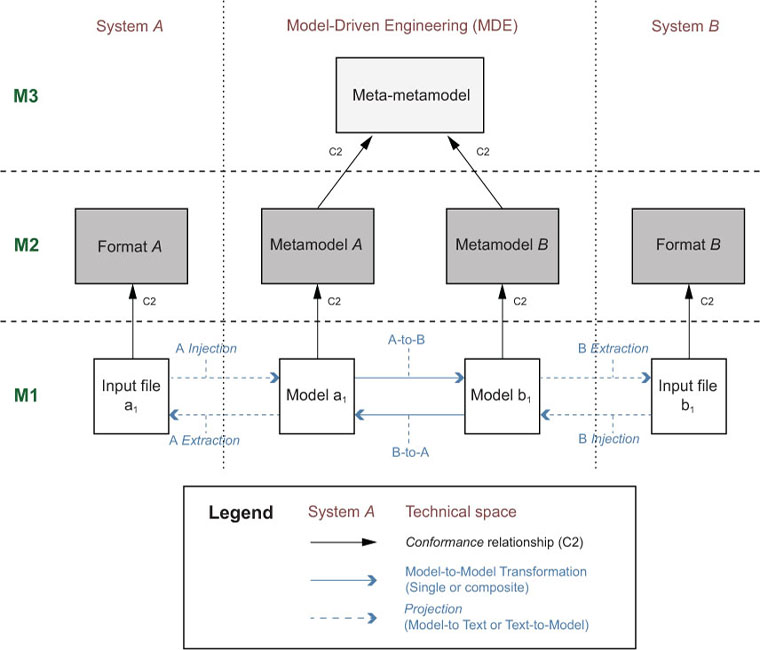
Figure 3.5: Generic interoperability bridge between two systems.
Semantic Mapping
Semantic mapping aligns the concepts coming from the domains of both systems. This mapping is implemented as a model-to-model transformation. The transformation re-expresses the domain concepts of system A into a set of equivalent domain concepts understandable by system B. Meta-models A and B can be manually generated, derived from the corresponding format description (e.g., a XML schema when the input or output are XML documents) or automatically created if the formats to bridge conform to a meta-format for which a bridge at the metametalevel is already available (i.e., a generic bridge between the XML Schema language and the MDSE meta-metamodel would allow an automatic transformation of all format descriptions, i.e., specific XML Schemas, to metamodels).
To summarize, a standard MDI bridging process is actually composed of three main consecutive parts:
1. injection (text-to-model);
2. transformation (model-to-model); and
3. extraction (model-to-text).
All the actual domain knowledge is specified in the “transformation” part. The “projection” parts (i.e., “injection” or “extraction”) only deal with technical/syntactical details, mainly concerning the storage formats.
Both projections and transformations can be either atomic or composite (i.e., chains of transformations). In most cases, such transformation chains are actually required in order to be able to split the overall problem into simpler ones, and so provide better extensibility, reusability, and maintainability for the bridge.
3.3 REVERSE ENGINEERING
Nowadays, almost all organizations, independent of their size and type of activity, are facing the problem of managing, maintaining, or replacing their existing systems. These legacy systems are often large applications playing a critical role in the company’s overall information system; they have been in use for a long time, they have been developed with now obsolete technology, and sometimes they are not completely documented. Therefore, the first problem to be solved when dealing with the evolution and/or modernization of legacy systems is to really understand what their architecture, provided functionalities, handled data, and enforced business rules and processes actually are.
This process of obtaining useful higher-level representations of legacy systems is commonly called reverse engineering, and remains today an open problem. MDSE comes to the rescue also in this scenario: Model-Driven Reverse Engineering (MDRE), i.e., the application of Model-Driven Engineering principles to provide relevant model-based views on legacy systems, has been recently proposed as a new solution to this important challenge.
The main goal of MDRE is to offer a better support for the comprehension of existing systems thanks to the use of model-based representations of those systems. Taking as input the set of artifacts associated to the various components of the legacy system (spanning from source code, configuration files, databases, partial documentation, and so on), MDRE aims to create a set of models that represent the system (where each model focuses on a separate aspect of the system at a different abstraction level).These models can then be used for many different purposes, e.g., metrics and quality assurance computation, documentation generation, and tailored system viewpoints, or as a first step in a software evolution or modernization process, as shown in Figure 3.6.
A MDRE process includes three main phases.
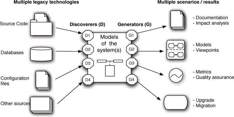
Figure 3.6: Model-driven Reverse Engineering.
• Model Discovery. In MDRE, the idea is to switch as soon as possible from the heterogeneous real world (with many legacy artifacts of different nature) to the homogeneous world of models, where all artifacts are represented as a set of interrelated models. This is what we call the model discovery phase. A good approach for creating these models is to first focus on quickly creating a set of initial models that represent the legacy system at the same (low) abstraction level, i.e., without losing any information in the process. These raw models can be directly manipulated with the arsenal of model representation and manipulation techniques we will see in the book and at the same time are detailed enough to be the starting point of any of the MDRE applications outlined in Figure 3.6.
• Model Understanding. Most MDRE applications will require the processing of the raw models discovered in the previous phase in order to obtain higher-level views of the legacy systems that facilitate their analysis, comprehension, and later regeneration. Thus, the second phase is the model understanding phase where chains of model manipulation techniques are employed to query and transform the raw models into more manageable representations (e.g., by omitting details that are not relevant for the MDRE scenario at hand or by deriving and making explicit the information hidden in the system structure, which helps to better understand the system itself).
• Model (Re)Generation. The processed models obtained at the end of the model understanding phase are finally used to generate and/or display the expected outcome of the reverse engineered process (e.g., the code of a refactored version of the system)
Figure 3.7 sketches a typical MDRE scenario where the aim is to migrate and redeploy an existing COBOL system into a Java platform.
In the first step (model discovery), we obtain the low-level models containing the full details of the COBOL code.
In the next step (model understanding), we raise the abstraction level of those models using model-to-model transformations and generating, for instance, UML diagrams with the domain information and rules extracted from the COBOL models. These models are then refactored or changed in various ways (e.g., to adapt them to the new policies in place in the organization or to adapt to new non functional requirements such as security or performance). The refactorings can be also implemented as model-to-model transformations (having UML models as both input and output of the transformation).
Subsequently, the models are used to generate the new running Java application. This is obtained through the third step (model generation), which transforms back the models to a lower-level representation if required (in this case, Java models) through a M2M transformation and then produces the proper Java code through a model-to-text transformation.
The Eclipse-MDT Modisco project9 offers several model discoverers, generators, and transformations that can be used as building blocks for your reverse engineering projects.
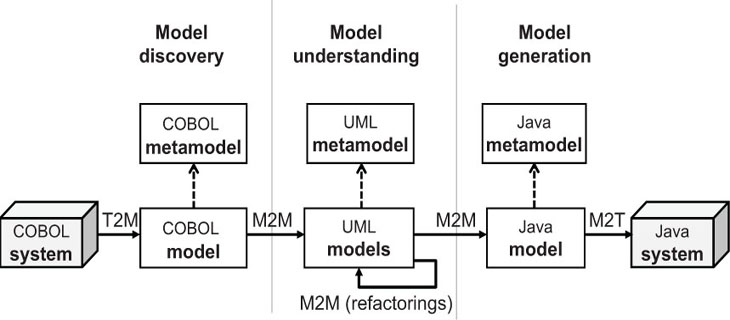
Figure 3.7: Example of a software modernization scenario.
1 As we will discuss later on, this is just an example. In some context we can go directly from the analysis models to the code or, when using model interpretation, skip the implementation phase and execute directly the models
2 This doesn’t mean that all models created during the process have to be executable but at least some of them must.
3 Note that this is the strategy that many MVC frameworks for popular languages like Ruby, PHP, or Python already follow; frameworks like Ruby on Rails, Symfony or Django automatically create a production-ready administration web interface based on the model definition.
4 Executable UML is also used to refer to the specific executable UML development method (xUML) proposed by S. Mellor [42] as an evolution of the previous Shlaer-Mellor method.
5 See http://www.omg.org/spec/ALF/ for the Alf Language specification or http://modeling-languages.com/new-executable-uml-standards-fuml-and-alf/ for a short introduction by Ed Seidewitz, the main language designer.
6 http://en.wikipedia.org/wiki/Turing_test
7 Models at runtime are also heavily employed in self-adaptive systems, i.e., systems that monitor the environment and are able to modify its behavior in response to changes on the environmental conditions. The information about how to adapt to these changes is usually expressed as a model that it is interpreted by the system at runtime.
8 See also the discussion thread in: http://www.theenterprisearchitect.eu/archive/2010/06/28/model-driven-development-code-generation-or-model-interpretation