
Developing your Own Modeling Language
Modeling has been often misunderstood as the process of just drawing pretty pictures. However, as we have already mentioned, models are much more than just pretty pictures. Models have to follow a clearly defined structure (exactly like program code), i.e., they have to conform to the associated metamodel representing the abstract syntax of the modeling language. Having a well-defined structure is the basis for applying operations on models such as loading/storing models from/to model repositories, querying and transforming the content of models, and checking the well-formedness of models to name just a few possible operations. In several modeling environments and tools, which use models as sketches or which were not built based on MDE practices, metamodels have a secret life hidden behind the user interface of the tools and, thus, are often invisible for the modelers. In simple usage scenarios, designers may not need to have a clear understanding of what is going on behind the curtains, but for complex MDE scenarios it is important to understand the big picture of MDE design. Especially, if you build your own tailored MDE environment, developing and using a metamodel is crucial as we will see in this chapter. The main reason for this is that other language aspects going beyond the language’s abstract syntax, such as the definition of the visual notation to be used when modeling, are heavily based on metamodels.
7.1 METAMODEL-CENTRIC LANGUAGE DESIGN
This chapter addresses the task of developing a new modeling language. In particular, we will delve into the task of defining the most important syntactical ingredients of modeling languages, namely the abstract syntax and the concrete syntax of the languages as introduced in Chapter 6.
7.1.1 ABSTRACT SYNTAX
The first ingredient is the definition of the modeling concepts and their properties by defining metamodels which play a role corresponding to grammars for textual languages.1 While a grammar defines all valid sentences of a language,2 a metamodel defines all valid models of a modeling language. Metamodels are defined with so-called metamodeling languages. Current metamodeling languages are heavily based on the core of structural object-oriented modeling languages, i.e., using classes, attributes, and associations—so to speak the core concepts of UML class diagrams. The term “metamodeling languages” originates from the fact that these kind of modeling languages are applied for modeling modeling languages.
The prefix meta in this context implies that the same technique is used to define the technique itself [41]. Another example for the usage of this prefix is metalearning, which stands for learning how to learn. Analogously, the term metamodeling stands for modeling how to model. The prefix meta may also be applied several times. Consider the term meta-metamodeling which stands for modeling how to metamodel. The language for defining how to build metamodels is therefore called meta-metamodel—a model which is able to represent all valid metamodels. However, as models are always an abstraction, metamodels and meta-metamodels only define the abstract syntaxes of the languages they represent. Other concerns such as the concrete syntaxes or semantics are currently not covered by these kind of models and have to be specified with additional artifacts as we will see later.
Metamodels containing classes, attributes, and associations define the modeling concepts and their properties, however modeling constraints are only partially described (see also Chapter 6). For example, as known from UML class diagrams, multiplicity constraints may be defined for attributes and association ends as well as types for attributes. Additional constraints stating more complex validation rules for models may be defined based on these metamodel elements using a constraint language. As presented before in Chapter 6 for UML class diagrams, OCL is the language of choice for defining constraints going beyond simple multiplicity and type constraints. Thus, OCL is also reused for metamodels to define these kinds of constraints. Recall, metamodeling languages are heavily based on UML class diagrams, thus OCL can be also employed for metamodels. For instance, a modeling constraint such as “A model element has to have a unique name” is not expressible in current metamodeling languages which are based solely on class diagrams. However, this constraint is easily specifiable in OCL as we shall see later in this chapter.
Metamodeling frameworks allow the specification of metamodels using dedicated editors as well as generating modeling editors out of the metamodels for defining and validating models. This means that metamodels are employed: (i) constructively by interpreting the metamodel as a set of production rules for building models and (ii) analytically by interpreting the metamodel as a set of constraints a model has to fulfill to conform to its metamodel.
7.1.2 CONCRETE SYNTAX
As mentioned before, metamodels only define the abstract syntax, but not the concrete notation of the language, i.e., the graphical or textual elements used to render the model elements in modeling editors. This is a major difference from EBNF-based grammars which define the abstract syntax as well as the concrete syntax of textual languages all at once. For example, if we define a programming language with an EBNF-based grammar, the keywords of the language are also determined by the grammar. For modeling languages, additional artifacts which refer to the metamodel elements are used to specify their concrete syntax. By the separation of the abstract and concrete syntax of a language, several concrete syntaxes may be defined for one modeling language. For instance, it is even possible to define both, a graphical as well as a textual concrete syntax for the same modeling language.
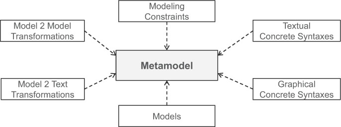
Figure 7.1: Metamodel-centric language design.
7.1.3 LANGUAGE INGREDIENTS AT A GLANCE
All language aspects going beyond the abstract syntax of a modeling language have in common that they are defined on the basis of the metamodel as it is illustrated in Figure 7.1. Thus, in the rest of this chapter, we first show how to define the abstract syntax of a modeling language including modeling constraints, and subsequently how graphical and textual concrete syntaxes on the basis of the abstract syntax are defined.3 Furthermore, we elaborate on current technologies available on top of Eclipse which may be employed for developing these syntactical aspects of a modeling language.
Please note that the transformation aspects such as model-to-model transformations and model-to-text transformations are also based on the metamodels of modeling languages. However, before we elaborate on transformation engineering aspects, we first introduce the prerequisites in this chapter, i.e., language engineering. Transformation engineering is the subject of the two subsequent chapters (cf. Chapter 8 for model-to-model transformations and Chapter 9 for model-to-text transformations). By using transformations, the semantics of a modeling language can be formalized by following different approaches [39]: (i) giving denotational semantics by defining a mapping from the modeling language to a formal language; (ii) giving operational semantics by defining a model simulator; or (iii) giving translational semantics by defining, e.g., a code generator for producing executable code. While the first two approaches are using model-to-model transformations, the latter is often implemented as model-to-text transformations.
In the following sections and chapters, we make use of a running example for demonstrating by-example how modeling languages and model transformations are actually developed.
As context for the running example, we assume the following situation. A software development company is repeatedly building simple Web applications, which all comprise similar functionality. To be more specific, the Web applications are mostly used to populate and manage persistent data in a database. The Web applications are realized by using a typical three-layered architecture following the Model-View-Controller (MVC) pattern [23]. As implementation technologies, a relational database for persisting the data as well as plain Java classes for retrieving and modifying the data are employed for building the model layer. Apache Tomcat is used as the Web Server, and the view layer, i.e., the user interface, is implemented as Java Server Pages and the controller layer is realized as Java Servlets.
The functionality supported by the Web applications is the following. For each table defined in the database, the following Web pages are needed: (i) showing a list of all entries as an overview; (ii) showing the details of one selected entry; (iii) creating a new entry; (iv) updating an existing entry; and finally (v) deleting an existing entry. Although the functionality is more or less the same for all tables, it has to be re-implemented again and again for each table.
Space for improvements. To be competitive, the company has to develop high-quality Web applications within short time frames to have a unique selling point. In order to achieve this, the following goals have been identified by the company to further rationalize its software development process.
• Homogeneity: Web pages should provide the same interface and the same functionality for all tables.
• Portability: The transition to new devices such as mobile phones as well as to emerging Web development frameworks should be easily achievable.
• Agility: Early customer feedback is appreciated to allow for an agile development process.
• Efficiency: Repetitive tasks in the development process should be eliminated.
MDE to the Rescue. For realizing these goals, the company decided to switch from a traditional development approach to a model-driven approach. Because UML is designed as a general-purpose modeling language for object-oriented systems, it lacks specific modeling support for Web applications. Thus, the company decided to develop its own DSML called simple Web Modeling Language (sWML) for defining their specific kind of Web applications in a platform-independent way. Furthermore, platform-specific models following the MVC pattern should be derived with model transformations from which the Java-based implementations are finally generated. By following this approach, the company expects to gain the following benefits.
• Homogeneity: Model transformations always generate the same kind of implementation for a given type of models.
• Portability: Having platform independent models of the Web applications allows the support of new devices and frameworks by providing additional transformations.
• Agility: Prototypes for black-box testing are rapidly generated from models.
• Efficiency: Having a concise DSML and transformations eliminates repetitive tasks.
In the following sections and chapters, it is shown how this DSML is implemented based on Eclipse-based technologies. Of course, it is not the goal to present complete descriptions of the involved modeling languages and transformations. Instead, some interesting excerpts are shown to demonstrate the different concepts, techniques, and tools. The implementation artifacts of the DSML are provided on the book’s website.4
7.3 ABSTRACT SYNTAX DEVELOPMENT
In this section, we explain how modeling languages are developed using metamodeling as the central technique. The standard metamodeling language defined by the OMG is the Meta Object Facility (MOF) [50]. Besides this OMG standard, several languages and tools for metamodeling have been proposed in the last decade, the most prominent of which is the Eclipse Modeling Framework (EMF) offering the metamodeling language Ecore. MOF and Ecore are both based on a subset of UML class diagrams for describing structural aspects, whereas Ecore is tailored to Java for implementation purposes. Thus, for explaining how to define metamodels, we first use simplified UML class diagrams corresponding to MOF and afterwards we discuss peculiarities of Ecore in Section 7.3.2.
One may raise the question: Why not just reuse UML for metamodeling as it is? Although MOF is very similar to the core of UML class diagrams, it is at the same time much more focused on the task of defining other modeling languages. For instance, MOF resigns n-ary associations, association classes, interfaces, and dependencies which are all concepts available in UML. The main differences between MOF and UML result from their fields of application. The domain of UML is object-oriented modeling in general. Thus, it is a comprehensive modeling language covering structural and behavioral modeling aspects as well as conceptual and implementation-oriented modeling. In contrast, the domain of MOF is much more focused—it is “simply” metamodeling. In a nutshell, MOF is a specialized DSML for metamodeling which reuses a subset of the UML core.
Benefits of metamodeling. By using a metamodeling language, the language designer may define the abstract syntax of his/her own modeling language being either a general or a domain-specific modeling language. Independent of the kind of language which is metamodeled, having an explicit metamodel conforming to a standardized meta-metamodel comes with several benefits.
• Precise language definition: There is a formal definition of the language’s syntax which is processable by machines. For example, the metamodels may be used to check if models are valid instances.
• Accessible language definition: With the core of UML class diagrams, a well-known modeling language is used to define metamodels. Thus, the knowledge of UML class diagrams is sufficient to read and understand the modeling language definitions in form of metamodels.
• Evolvable language definition: Metamodels may be subject to modifications as any other model is. For example, the language may be extended with new modeling concepts by providing new subclasses for already existing metamodel classes. Having an accessible language definition further contributes to an easy adaptation of modeling languages based on metamodels.
In addition, generic tools, which are metamodel agnostic, may be developed based on the meta-metamodel level. For example, current metamodeling frameworks provide sophisticated reflection techniques to develop programs which are applicable to all instances of metamodels conforming to a particular meta-metamodel. Here are some examples.
• Exchange formats: Based on the meta-metamodel, there is support to serialize/deserialize models into XML documents which are exchangeable between tools supporting the same meta-metamodel.
• Model repositories: Similar to model exchange, models may be stored to and retrieved from a model repository based on generic storage/loading functionalities.
• Model editors: For modifying models, generic editors may be provided which are applicable on all models, irrespective which modeling language is used.
The list of such generic support is not limited. For example, simple programs may be developed for computing model metrics, e.g., how many model elements are comprised by a model. But also sophisticated tool support may be developed based on the meta-metamodel level, e.g., model comparison and model versioning support as we shall see later in Chapter 10.
Four-layer metamodeling stack. Current metamodeling tools mostly employ a four-layer metamodeling stack. An overview on this metamodeling architecture is shown in Figure 7.2. The upper half of this figure is concerned with language engineering, i.e., building models for defining modeling languages, while the lower half is concerned with domain engineering, i.e., building models for particular domains. On the top layer—named M3 in OMG terms—there reside the metamodeling languages which specify the metamodeling concepts used to define metamodels. Normally, metamodeling languages are rather focused languages which offer a minimal set of concepts. In order to have a finite metamodeling architecture, these languages are most often reflexively defined, meaning that they are able to describe themselves. Thus, no additional language on top of M3 is needed to define M3, but you can think of having again the same language on M4 as on M3. Also, from a practical point of view, having a different language on M4 than on M3 seems to bring no further benefits. It would be again only a structural modeling language offering similar expressibility. MOF and Ecore are designed as reflexive languages typically used on the M3 layer.
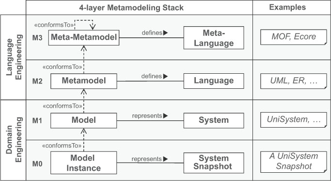
Figure 7.2: Four-layered metamodeling stack at a glance (based on [41]).
On the M2 layer, the metamodels reside which represent modeling languages (e.g., UML and ER) by defining their modeling concepts. These metamodels can be instantiated to build models on the M1 layer of the metamodeling stack. Models on the M1 layer represent systems such as a university management system (cf. UniSystem in Figure 7.2) and typically define domain concepts by using the language concepts defined by the metamodels on M2. On the M0 layer there are the instances of the domain concepts which represent real-world entities, e.g., a snapshot of the university management system, at a given point in time.
The four-layer metamodeling stack assumes that a model on layer M conforms to a model on layer M+1. This relationship is called conformsTo. Thinking in graph structures, this means that a model is a graph consisting of nodes and edges. This graph has to fulfill the constraints of the next higher level. If each element (node or edge) on layer M is fulfilling the constraints given by its type element on layer M+1 from which it is instantiated, the model on layer M conforms to its type model, i.e., the assigned model on layer M+1. In case of M0 and M1, the instances of a domain model have to conform to the domain model. In case of M1 and M2, the model has to conform to its metamodel. In case of M2 and M3, the metamodel has to conform to its meta-metamodel. Finally, in case of M3, the meta-metamodel has to conform to itself, because the conformsTo relationship is reflexive.
7.3.1 METAMODEL DEVELOPMENT PROCESS
One way to think about a metamodel is seeing it as the schema to store its models in a repository. Therefore, developing a metamodel is similar to developing a class diagram for a concrete domain. One has to identify the concepts that should be supported by the language, and, subsequently, these concepts have to be concisely specified by using a metamodeling language. As soon as the first metamodel version is available, the modeling language may be tested by using generic editors which allow the interpretation of the metamodel to build an example model. The editors may be used to model some reference examples to get a first impression whether all concepts have been defined properly or if some changes in the metamodel are necessary. To summarize, the metamodeling process in its simplest form is a three-step, iterative, and incremental process.
• Step 1: Modeling domain analysis: According to [37], three aspects have to be considered in the first phase of developing a modeling language: the purpose, realization, and content of the language. Especially, the last point is the most challenging: the identification of modeling concepts and their properties. For this, the modeling domain that should be supported by the modeling language has to be analyzed. A pragmatic way to do this is to find several reference examples [55] that should be expressible in the modeling language to be developed—so to say the requirements for the language are defined by-example.
• Step 2: Modeling language design: A metamodeling language is used to formalize the identified modeling concepts by modeling the abstract syntax of the language and modeling constraints should be formalized by using OCL. The output of this step is a metamodel for the modeling language to be developed.
• Step 3: Modeling language validation: The metamodel is instantiated by modeling the reference examples to validate the completeness and correctness of the developed metamodel. Furthermore, other general principles of language design such as simplicity, consistency, scalability, and readability also have to be considered. The result of this step provides important feedback for the next iteration of the metamodel development process.
Please note that this process is currently only concerned with the development of the abstract syntax of the language. To get feedback from domain experts, a concrete syntax is also needed in order to have an accessible modeling language. Thus, in practice, the complete process should also involve the development of the concrete syntax of the language. However, before we discuss how to develop a concrete syntax, the basics of developing the abstract syntax have to be understood. Thus, we discuss the development of the abstract and concrete syntax sequentially in this book due to didactic reasons, but we strongly encourage to develop both syntactical concerns together in practical settings.
To make the metamodel development process more concrete, it is now instantiated for developing a metamodel for sWML.
Step 1: Modeling Domain Analysis
Several sources of information may be exploited for finding the appropriate set of modeling concepts. Which sources to tap depends on the purpose of the modeling language that should be developed. If a modeling language should be defined for abstracting from low-level program code, a major source of information may be existing programs. For example, reoccurring patterns found in the program code may be abstracted to modeling concepts. If the modeling language is tailored to a specific domain, document analysis or expert interviews may be a proper choice to derive the necessary modeling concepts. All these activities should lead to concrete reference examples which are beneficial for communication with domain experts, testing the modeling language and code generators, etc. Thus, in the following we show how the reference example approach is used to develop the modeling concepts of the sWML language.
Let us assume that in a workshop, a first sketch of modeling Web applications (cf. Figure 7.3) has been created based on an already existing Web application of a conference management system. For instance, the Web application shows which talks and tutorials are offered by the conference. Based on this model sketch, we elaborate on the purpose, realization, and content of sWML.
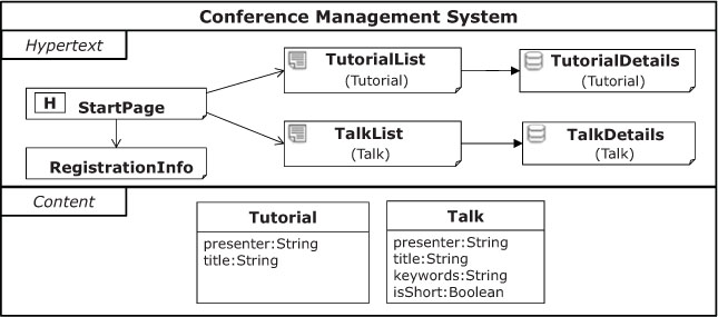
Figure 7.3: sWML model sketch.
Language purpose. sWML should allow the modeling of the content layer and the hypertext layer of Web applications. The content layer defines the schema of the persistent data which is presented to the user by the hypertext layer in form of Web pages. In addition, the hypertext layer defines the navigation between Web pages and the interaction with the content layer, e.g., querying content from the database.
Language realization. To support different sWML user types, a graphical syntax should be defined which may be used for discussing with domain experts and for reasoning on the structure of the hypertext layer and the content layer. However, for making a smooth transition from the standard development process based on programming languages to the model-driven approach, additionally, a textual syntax should be provided for developers who are familiar and used to work with text-based languages.
Language content. A sWML model consists of a content layer and a hypertext layer which reflects the previously mentioned purpose of the language.
A content model contains an unrestricted number of classes. Classes have a unique name (e.g., Tutorial) and multiple attributes (e.g., Tutorial.title). Attributes have an assigned name and type. For instance, permitted types are: String, Integer, Float, Boolean, and Email. For each class one must select one of its attributes as its representative attribute which is not explicitly shown in the concrete syntax to keep the syntax concise.
Hypertext models contain different kinds of pages, where each page has a name. Exactly one page is the homepage of the Web application. Later on, this page (and all directly linked pages of the homepage) can be accessed by all other pages of the Web application. Pages are subdivided into static and dynamic pages. Static pages represent only static content, e.g., a collection of useful links. In contrast, dynamic pages represent dynamically generated content coming from the database. Thus, a dynamic page always has a relationship to a class defining the type of the displayed instances. The relationship to the used classes is shown in parentheses under the name of the page. Dynamic pages are further subdivided into details pages and index pages having specific icons. Index pages show all instances of a class in terms of a list, e.g., a list consisting of all tutorials of the conference, showing only the representative attribute of the instances. In contrast, details pages always show exactly one instance, e.g., one tutorial, with all its attributes.
Links represent the navigation between pages by pointing from a source page to a target page. On the source page, the link is visualized to the user. Thus, a page usually knows its links pointing to other pages but it is unaware of incoming links. Two kinds of links are distinguished: (i) non-contextual links (NCLinks) are standard links, which do not transport any information, e.g., a link to a static page; and (ii) contextual links (CLinks) transport information to the target page, e.g., to transfer data needed to compute the content of the target page, e.g., to select the instance shown by a details page.
Essence of the abstract syntax. The first version of the language content description comprises different kinds of information. Primary, the modeling concepts are introduced by defining their properties which is necessary input for developing the abstract syntax. But sometimes other aspects such as the notation and semantics of the modeling concepts are discussed. Thus, from this text, the essence of the abstract syntax has to be filtered out, before the first version of the metamodel can be build. As a result, a list of concepts and their properties is produced. For our example, the table shown in Figure 7.4 summarizes the most important sWML concepts and their properties. In particular, intrinsic properties, having only primitive data values, must be distinguished from extrinsic properties, which represent relationships between modeling concepts.
Step 2: Modeling Language Design
The modeling concept table shown in Figure 7.4 is transformable into a metamodel as illustrated in Figure 7.5 for sWML. First, concepts are transformed to classes, intrinsic properties into attributes, and extrinsic properties are defined as associations between classes. Having this initial structure, one can reason about further modeling constraints. For attributes, types have to be introduced such as String, Integer, and Boolean. If there is a range of possible values, enumerations may be defined as for the SWMLTypes (cf. Figure 7.5). For the association ends, upper and lower bounds of multiplicities have to be set properly.
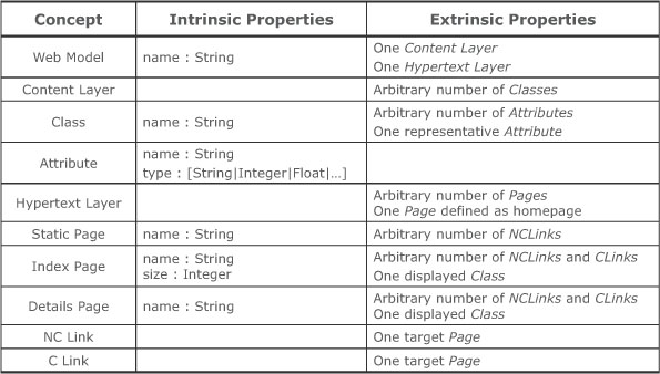
Figure 7.4: Modeling concept table for sWML.
Furthermore, one has to reason about the containment structure of the metamodel, because elements in models are often nested. For example, consider the content layer which contains classes, whereas classes again contain attributes. This containment structure has to be defined in the meta-model by declaring some association ends as compositions. The most important consequence of defining a association ends as compositions is that when the container element is deleted all contained elements are deleted, too.
To enhance readability and extensibility of the language definition, inheritance relationships between classes are introduced to reuse attributes and associations defined for superclasses also for subclasses (cf. abstract classes for pages, and links). For this, refactorings for improving the structure of class diagrams may be applied on metamodels as well. For example, shifting up attributes from subclasses to superclasses, extracting superclasses from existing classes, or substituting an association with an explicit class to define additional properties for the association are recurring operations on metamodels. At the end of the day, metamodels should fulfill the well-known quality attributes of object-oriented modeling.
Discourse. For defining a modeling concept, we have the following three possibilities in meta-modeling languages: define it as a class, attribute, or association. Consider for instance the homepage concept in our example language. The first option (using a class) would result in an explicit class HomePage. However, if we would like to switch a homepage into a normal page, we have to delete the homepage, create a new page, and set all features using the previous values of the homepage for this new page. The second option (using an attribute) would result in having an Boolean attribute in the class Page, e.g., called isHomepage. Thus, for each page we can dynamically decide if the page represents a homepage or not. Of course, we may need a modeling constraint which ensures that for each Web application, only one homepage exists. Using the third option (an association), as we have done in the metamodel shown in Figure 7.5, allows to mark exactly one page as the homepage within the set of all pages contained by the hypertext layer. Thus, we can dynamically change the homepage and do not need to add an additional well-formedness rule. This discussion shows that when deciding how to represent a modeling concept in the metamodel, one has to reason about the advantages and disadvantages of using classes, attributes, or associations to represent the concept. This decision has a major impact on the actual modeling possibilities influencing the modeling experience the users will have. Thus, it is important to consider feedback from users to improve the modeling language by switching between different metamodeling patterns.
Note that if a more powerful content modeling language is required, one option is to import existing metamodels as, e.g., the class diagram part of the UML metamodel, instead of remodeling the complete content modeling language from scratch.
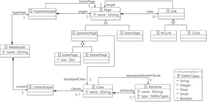
Figure 7.5: Metamodel for sWML.
Modeling constraints. As already mentioned, several constraints cannot be defined by current meta-modeling languages using only graphical elements. Thus, OCL is employed to define additional constraints as so-called well-formedness rules. These rules are implemented in OCL as additional invariants for the metamodel classes and have to hold for every model. Thus, the constraints are defined on the metamodel and validated on the model level.
For the actual validation, several strategies may be used. For instance, a lazy evaluation of the OCL constraints may be possible if complex constraints have to be evaluated which leads to a costly evaluation. In such cases, the validation may be done only after saving a model or before a model is translated to another model or code. However, there are also approaches which allow for an optimized evaluation of OCL constraints. Having such support or using only local constraints (which may be evaluated by only analyzing one instance without complex navigation and iteration to/over other elements) may allow for instant evaluation of the constraints after every edit operation on a model.
OCL invariants for sWML. In the following, we introduce some examples for well-formedness rules for sWML in natural language and subsequently show the corresponding OCL invariants.
Rule 1: A Class must have a unique name within the Content Layer to avoid name clashes.
![]()
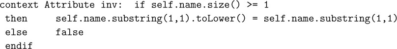
Rule 2: The representative Attribute of a Class must be taken out of the set of Attributes contained by the Class.
![]()
Rule3: A page must not contain a non-contextual link to itself, because navigating such a link would result in exactly the same page as shown before the navigation.

Benefits of using OCL constraints. By introducing OCL invariants for metamodel classes, a modeling language is more precisely defined leading to models with higher quality. This is especially important when employing models for code-generation. Otherwise, some problems may not be detected until the final implementation is generated where the problems may manifest as compile-time and runtime errors, or remain undetected in the worst case.
Besides well-formedness rules, with OCL invariants, modeling guidelines can be defined, introducing, for instance, naming conventions such as all attribute names have to start with a lower case letter.
Finally, rules for representing best practices may be implemented as OCL invariants. For instance, assume that a class should not have more than six attributes:
![]()
Step 3: Modeling Language Validation
Current metamodeling frameworks allow direct instantiation of the metamodel by using generic modeling editors. This means, to test the abstract syntax of a modeling language, no additional implementation effort is needed. Now the question arises how to define a model using its abstract syntax?
Because we are using object-oriented metamodeling languages to define metamodels, models are a collection of objects. Thus, it is common to represent models by UML object diagrams (cf. also Chapter 6). In UML, object diagrams allow the sketching of instantiations of class diagrams by using:
• objects for instantiating Classes;
• values for instantiating Attributes; and
• links for instantiating Associations.
Object diagram notation. The notation of object diagrams is summarized in Figure 7.6. In the upper half of this figure, a class diagram is shown which is instantiated in the lower half by using an object diagram. Objects are notated similarly to classes using a rectangle, with the difference that in the first compartment the identifier of the object is given in combination with its type (e.g., cf. a01 : ClassA in Figure 7.6). Of course, the type has to correspond to the name of a class in the metamodel. Attribute values are defined in the second compartment in so-called attribute slots. Links are notated like associations between objects. This notation can be used independently of the concrete metamodeling level. Normally, object diagrams are employed to instantiate class diagrams representing domain models, but they can be also used to instantiate metamodels and even meta-metamodels.
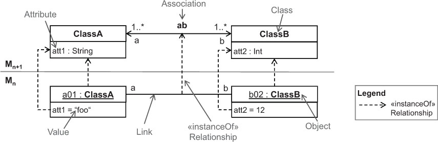
Figure 7.6: Object diagrams as instances of class diagrams.
For instantiating models from metamodels the same rules as instantiating object diagrams from class diagrams apply. First, only concrete classes can be instantiated. Second, data types such as enumerations act only as constraints for the attribute values, but cannot be instantiated. Third, the meta-features of attributes and references, i.e., multiplicities and uniqueness constraints, act only as constraints for the object diagrams. Finally, the containment references are also just represented as links in object diagrams. However, if a container object is deleted all directly and indirectly contained elements, i.e., objects linked by containment references, are automatically deleted. To enhance the readability, containment links are shown in the following by using the black diamond notation.
Instantiating the sWML metamodel. In Figure 7.7, the object diagram for an excerpt of the sketched example model (cf.Figure 7.3) is shown. To better illustrate the relationships between (i) metamodel and model level and (ii) abstract and concrete syntax, the identifiers of the objects are annotated in the concrete syntax as special labels to the model elements. As can be seen in this figure, all model elements are represented as objects in the abstract syntax.
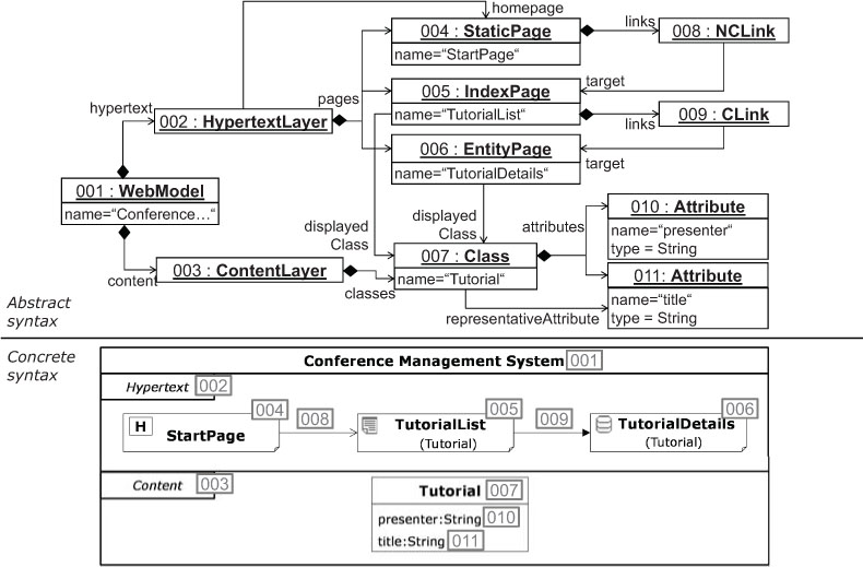
Figure 7.7: sWML model’s abstract syntax.
Feedback for metamodel improvements. When testing metamodels, several changes may be identified which are needed to represent and formalize the language properly. For example, the following simple modifications are quite common: mark classes as concrete/abstract, set references as containment/non-containment, restrict/enlarge multiplicities of features, make feature types more specialized/generalized, or just delete existing and introduce new elements. Not only simple modifications may be required, but also more complex changes such as refactorings for switching between metamodeling patterns, as explained before, or for the introduction of design patterns, e.g., the composition pattern, may be needed to improve the modeling language definition.
Note that having to change the metamodel in cases where instances of them already exist may lead to troubles when the changes break the conformance relationships between the metamodel and the models. For instance, the models may be no longer loadable in the modeling editors if metamodel elements are renamed or deleted. How to deal with such metamodel/model co-evolution problems is discussed in Chapter 10.
7.3.2 METAMODELING IN ECLIPSE
After having presented how metamodels are defined (using UML class diagrams) and instantiated (using UML object diagrams) on a conceptual level, we now discuss roughly how these tasks are supported by EMF (Eclipse Modeling Framework). EMF comes with its own metamodeling language Ecore and tool support for defining Ecore-based metamodels as well as instantiating those. Please note that this subsection gives only a short overview on EMF and its base functionalities. For further information, we kindly refer the interested readers to dedicated EMF resources mentioned on our book website.5
An overview on Ecore’s modeling concepts is depicted in Figure 7.8. The main concepts of Ecore are EClassifiers comprising EClasses, EDataTypes, and EEnums, as well as EStructuralFeatures comprising EAttributes and EReferences. Thus, the same object-oriented concepts are provided by Ecore as known from MOF. EClasses are the first-class citizens in Ecore-based metamodels. An EClass may have multiple EReferences and EAttributes for defining its structural features as well as multiple superclasses. An EAttribute is part of a particular EClass and has a lower- and an upper-bound multiplicity. Additionally, it can be specified as being ordered and unique in case the attribute is multi-valued. The type of an EAttribute is either a simple EDataType or an EEnum stating a restricted list of possible values, i.e., the EEnum’s literals (cf. EEnumLiterals). EString, EBoolean, EInt, and EFloat are part of Ecore’s default data type set. Analogous to EAttribute, an EReference is part of a specific EClass and also has a lower and an upper bound multiplicity. An EReference refers to an EClass and optionally to an opposite EReference for expressing bi-directional associations. Besides, an EReference can be declared as a being ordered, unique, and as a containment reference, i.e., if the container object is deleted, all contained objects are deleted as well. Finally, EPackages group related EClasses, EEnums, EDataTypes, as well as other EPackages.
For specifying Ecore-based metamodels in Eclipse, there are several concrete syntaxes available supported by different editors. First, EMF comes with a tree-based editor for modeling metamodels in their abstract syntax similar to object diagrams, but using the containment hierarchy to form an explicit tree structure. However, as working with the modeling language’s abstract syntax does not scale, it is recommended to use editors supporting concrete syntaxes for Ecore. There are several graphical editors for Ecore, e.g., the Ecore tools project,6 which allow to model Ecore metamodels using a similar syntax as UML class diagrams. In addition, there are other approaches which define Ecore metamodels textually such as KM37 and Emfatic.8
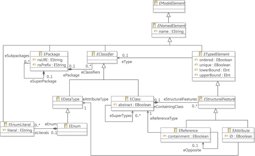
Figure 7.8: Overview of Ecore’s main language concepts.
OCL support for Ecore. For defining OCL constraints for Ecore-based metamodels several plugins are available in Eclipse. Eclipse OCL9 is a project focusing—as the name suggests—on the implementation of the OCL standard within Eclipse. An interesting subcomponent in this project is OCLinEcore10 which allows the definition of invariants for Ecore-based metamodels and the evaluation of these constraints within modeling editors. An alternative project is the Dresden OCL Toolkit11. Further support for defining and evaluating invariants for EMF-based models is provided by the Epsilon Validation Language12 of the Epsilon project and the Check language13 of the oAW project. Both languages are inspired by OCL, but provide a slightly different syntactic appearance related to Java.
7.4 CONCRETE SYNTAX DEVELOPMENT
As mentioned before, the abstract syntax development process is supported by several OMG standards. For the concrete syntax definition there is currently just one OMG standard available, namely the Diagram Definition (DD)14 specification, which allows defining graphical concrete syntaxes. However, in the current UML metamodel definition in the UML standard document [51], the concrete syntax is only shown in so-called notation tables (one column is used for modeling concepts and one for their notation elements) and by giving some examples. A more formal definition of the UML concrete syntax is not given. This is in contrast to traditional text-based language engineering approaches where also the concrete syntax is formally defined by using, e.g., EBNF-based grammars.
Having the concrete syntax formally defined opens the door for using sophisticated techniques such as automatic generation of editors which allow to manipulate the artifacts in their concrete syntax. Having such editors is a must for the productive usage of models in practice. Without having a formal definition of the concrete syntax, these editors have to be implemented manually which require much effort leading to high investments to realize a MDE environment.
Fortunately, there are several emerging frameworks which provide specific languages to describe the concrete syntax of a modeling language formally as well as generator components which allow the generation of editors for visualizing and manipulating models in their concrete syntax. Modeling languages are often considered to be graphical languages, only, but as there exist graphical programming languages, there is also the possibility to define a textual syntax for modeling languages. Thus, two kinds of concrete syntaxes are currently supported by existing frameworks: Graphical Concrete Syntaxes (GCS) and Textual Concrete Syntaxes (TCS).
Having a textual language allows the encoding of information using sequences of characters like in most programming languages, while graphical languages encode information using spatial arrangements of graphical (and textual) elements [45]. Thus, textual representations are one-dimensional, while most of the graphical languages allow for two-dimensional representations. For example, in UML diagrams each model element is located in a two-dimensional modeling canvas.
Regardless of the kind of concrete syntax developed, it is defined by mapping the modeling concepts described in the metamodel to their visual representations—so to speak, the visual notation introduces symbols for the modeling concepts (cf. Figure 7.9). The term “visual notation” is used in this chapter for summarizing both, textual and graphical notations. Having the symbols for the modeling concepts allows to visualize the models, either by using only text or also graphical elements arranged in a diagram.
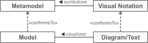
Figure 7.9: Visual notation: introducing symbols for modeling concepts.
In the following, we elaborate on different approaches for defining a visual notation for modeling languages and demonstrate how a GCS and TCS is developed for sWML.
7.4.1 GRAPHICAL CONCRETE SYNTAX (GCS)
Before we delve into details on how a GCS is defined for a metamodel, we first elaborate on the anatomy of a GCS.
Anatomy of graphical languages. A GCS has to define the following elements: (i) graphical symbols, e.g., lines, areas, complete figures such as SVG graphics, and labels for representing textual information, e.g., for visualizing the names of modeling elements; (ii) compositional rules which define how these graphical symbols are nested and combined. For instance, a label visualizing the name of a model element is centered within a rectangle representing the model element; (iii) mapping the graphical symbols to the elements of the abstract syntax for stating which graphical symbol should be used for which modeling concept, e.g., a specific model element type is visualized by a rectangle.
Current graphical modeling editors use a modeling canvas which allows the positioning of model elements in a two-dimensional raster. Each element has an assigned x,y coordinate which normally stands for the upper-left corner of the graphical symbol. The model elements are mostly arranged as a graph which is contained in the modeling canvas. This graph is called diagram and represents a graphical view on the model. Please note that not all model information is actually shown in the modeling canvas. Several property values are only shown and editable in an additional property view.This, on the one hand, allows accessing and editing every property of a model element, while, on the other hand, avoids overloading the diagram with too much information.
In Figure 7.10, we show a small excerpt of a generic metamodel for GCSs.First, the metamodel states that a diagram consists of different elements which are either a node, edge, compartment, or label. These element types are sufficient for most modeling languages. Nodes and edges are the important concepts to form graphs and are represented by shapes and lines, respectively. Compartments, mostly represented by shapes, are used to nest elements, i.e., diagrams are nested graph. Finally, labels are used to annotate nodes and edges with additional information, i.e., diagrams are also attributed graphs.
For stating the relationship between modeling concepts and symbols, we have a mapping between abstract syntax and concrete syntax elements. In general, an abstract syntax element, such as a class, attribute, and association, is mapped to a concrete syntax element.15 For the diagram itself, the root element of the containment hierarchy of the metamodel is usually selected which is able to contain directly or indirectly all other model elements. All other metamodel classes are normally mapped to nodes and associations either to compartments in case of containment associations or to edges in case of non-containment associations. Attributes are mapped to labels residing within a node or are located near a node or a edge. There are also cases where a class may be mapped to an edge. Assume we have a class in the metamodel representing generalization relationships. In this case, instances of this class are represented as edges where the references of the class are used to determine the source and the target nodes of the edges.
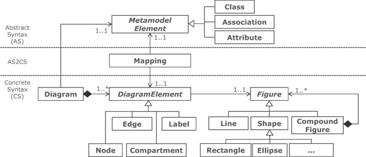
Figure 7.10: A generic GCS metamodel.
sWML Example. If we take another look at Figure 7.7 (p. 91) which shows the abstract syntax for the reference modeling example given in sWML’s concrete syntax, we may encounter the mapping between the modeling concepts and the symbols used in sWML. For example, we see immediately that Link objects are visualized as edges, while Page objects are visualized as nodes having specific icons attached based on their types.
Before we demonstrate how to develop a GCS for sWML, we first give an overview on different GCS development approaches.
Approaches to GCS development. To specify a GCS for a modeling language defined as an Ecore-based metamodel, the following three approaches are currently supported by different Eclipse projects.
Mapping-centric GCS. Protagonists from this category provide dedicated modeling languages for describing the GCS and the mapping from the concrete syntax to the abstract syntax. This approach is followed by the Graphical Modeling Framework16 (GMF).The language engineer has to define: (i) a .gmfgraph model which defines the graphical elements used to visualize model elements (cf. class Figure and DiagramElement in Figure 7.10); (ii) a .gmftool model which specifies the tool palette,17 in particular, which icons are used to produce which model elements; and finally, (iii) a .gmfmap model which actually defines the mapping between elements defined in the metamodel and the graphical elements defined in the .gmfgraph model (cf. class Mapping in Figure 7.10). A generator transforms these three models into code which represents the implementation of a fully-fledged graphical modeling editor. Please note that GMF may be also seen as a DSML with a code generator component. Thus, the development of graphical modeling editors is achieved by applying MDE techniques.
Also, the OMG Diagram Definition (DD) uses this approach, exploiting MOF and QVT.
Annotation-centric GCS. Approaches from this category directly annotate the metamodel with information about how the elements are visualized. This approach is supported by EuGENia18. The EuGENia framework allows to annotate an Ecore-based metamodel with GCS information by providing a high-level textual DSML. This annotated information is used by a dedicated transformation component to generate the afore mentioned GMF models. Therefore, EuGENia follows itself a model-driven approach to generate graphical editors by reusing GMF as the transformation target. EuGENia provides high-level annotations that hide the complexity of GMF and lowers the entrance barrier for creating initial versions of GMF-based editors. While EuGENia is very useful as a kick starter for developing graphical modeling editors, it doesn’t stop there and can be also used all the way to the final polished version of the graphical editor.
API-centric GCS. There are also approaches allowing the implementation of graphical modeling editors directly on the code level by providing a dedicated programming framework.
This approach is taken by Graphiti19. Graphiti provides a powerful programming framework for building graphical modeling editors. A language engineer has to extend the provided base classes of Graphiti to define the concrete syntax of a modeling language. In particular, the framework provides classes for developing a pictogram model describing the visualization and the hierarchy of concrete syntax elements (similar to the .gmfgraph model) and a link model for establishing the mapping between abstract and concrete syntax elements (cf. .gmfmap model of GMF).
Another protagonist is the Graphical Editing Framework20 (GEF), which provides low-level functionalities for graphical editors; thus, GEF is considered to be the infrastructure for other GCS approaches rather then a framework for directly implementing graphical modeling editors. Although this would be possible, much more effort is required.
Finally, GMF also provides a powerful API for programming modeling editors, but it is recommended to start with the GMF models and only refine the generated editors on the code level. Thus, GMF is classified as a mapping-centric approach, although it is possible to start programming a modeling editor from scratch.
Defining a GCS for sWML in EuGENia. To give the reader an idea how to define a GCS for a concrete example, we employ EuGENia for developing a GCS for sWML. We selected EuGENia, because it allows to introduce GCS approaches on an appropriate level of abstraction. In EuGENia there are several annotations available for specifying the GCS for a given Ecore-based metamodel. In the following, the main annotations are first enumerated and subsequently applied for sWML.
• Diagram: The root element of the abstract syntax representing the model, i.e., the element containing (directly or indirectly) all other elements, is a perfect match for representing the modeling canvas. EuGENia uses the Diagram annotation to mark this class in the metamodel.
• Node: Instances of metamodel classes are often visualized as nodes within the diagrams. Thus, EuGENia allows annotating classes with the Node annotation. This annotation has several features, such as selecting the attribute of the annotated class which should be used as the label for the node, layout information such as border styles, colors, and either an external figure (e.g., provided as a SVG graphic) or a predefined figure by EuGENia (e.g., rectangle or ellipse) may be used to render the node.
• Link: The Link annotation is applicable to classes as well as to non-containment references that should appear in the diagram as edges. This annotation provides attributes for setting the style of the link, e.g., if it is dashed, and the decoration of the link end, e.g., if the link end should be visualized as an arrow. For classes annotated with the Link annotation, additionally, the source and target references used as end points for the link have to be selected from the available references of the classes.
• Compartment: Containment references may be marked with this annotation. It defines that the containment reference will create a compartment where model elements that conform to the type of the reference can be placed within.
• Label: Attributes may be annotated with the Label annotation which implies that these attributes are shown in addition to the label used as name for the node or link.
We now discuss two excerpts of the GCS definition for sWML (cf. Figs. 7.11 and 7.12). Annotating the metamodel, as in the upper part of the figures, allows to render the models as schematically illustrated in the bottom of the figures.
The first excerpt (cf. Figure 7.11) comprises three annotations. The first one is used to select the element which is used to represent the diagram. Thus, the class WebModel (the root element of sWML) is annotated with Diagram. Furthermore, the diagram should allow placing a hypertext layer within the canvas. Thus, a Compartment annotation is necessary for the containment reference hypertext. This annotation states that it is possible to add a hypertext layer to the diagram. Finally, hypertext layers should be visualized as nodes represented as rectangles. Thus, we employ a Node annotation to the HypertextLayer class and set the figure attribute accordingly. If no label is specified, the default label for a modeling element is its type name.
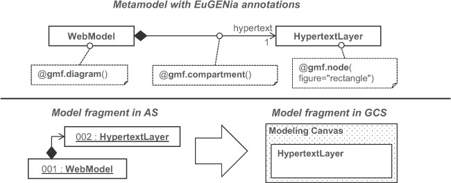
Figure 7.11: GCS excerpt 1: Diagram, Compartment, and Node annotations.
The second excerpt (cf. Figure 7.12) defines that instances of the Page class are visualized as rectangles21 where the name of the page is shown as the label of the rectangle. This is achieved by a similar Node annotation as before for the HypertextLayer class in Figure 7.11. Instances of the Link class should be visualized as edges between the nodes representing the pages. Thus, the class Link is annotated with a Link annotation. Several attributes have to be defined for the proper visualization such as which references are used as the target for the links (the source for a link is per default its container which is applicable for our case) and how the links should actually look like. In this example, the link end at the target side should be visualized as an arrow to indicate the navigation direction of the hyperlink. Please note that the GCS definitions defined for superclasses are applicable also for their subclasses in case no specific definitions have been defined (i.e., in Figure 7.12 also the graphical notation for contextual and non-contextual links is defined).
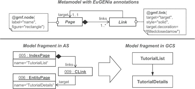
Figure 7.12: GCS excerpt 2: Node and Link annotations.
7.4.2 TEXTUAL CONCRETE SYNTAX (TCS)
In the early days of MDE, modeling languages have been considered to be solely graphical languages mainly influenced by precursors of UML. However, in the meantime, this view has changed fundamentally. First, the usefulness of having a TCS for a modeling language has been recognized in domains where users are familiar working with textual documents. Second, powerful frameworks emerged which allow for the user-friendly development of textual editors for modeling languages.
The fundamental assumption of textual specifications is that the comprised text consists of a sequence of characters. Of course, for defining meaningful specifications, not every arbitrary sequence of characters represents a valid specification. Thus, a grammar is needed that specifies all valid character sequences. As we shall see later, from a metamodel, only a generic grammar may be derived which allows the generic rendering of models textually as well as the parsing of text into models. However, syntactic sugar is highly appreciated when working with textual languages. In particular, language-specific keywords enhance the readability of textual specifications a lot. Thus, some additional concepts are needed for developing a TCS.
Anatomy of textual languages. As we have seen before, a graphical syntax consists of several different types of elements such as different kinds of geometrical figures. Also textual languages make use of different types of elements which are explained based on our running example sWML. Let us assume we have an excerpt of the conference model as illustrated in the left-hand side of Figure 7.13. In the hypertext layer we have the IndexPage TutorialList which visualizes all instances of the Class Tutorial defined in the content layer. A possible textual visualization of this example is shown in the right-hand side of Figure 7.13 which provides the same information as the graphical visualization, but using a TCS.
By taking a closer look at this example, the following kinds of TCS elements can be identified which are of paramount importance for every TCS, in general.
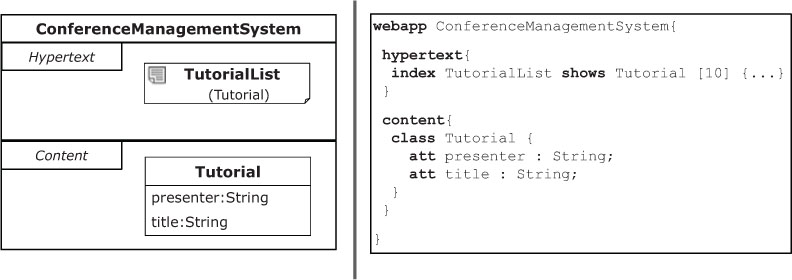
Figure 7.13: sWML model excerpt in GCS and TCS.
• Model information: Obliviously, a TCS for models has to support the model information stored in the abstract syntax. In our example, we have to define the name of the model elements and for attributes also the type. This is analogous to graphical languages where labels are normally used for stating such information.
• Keywords: A keyword is a word that has a particular meaning in the language, i.e., it stands for a particular language construct. In our example, keywords are used for introducing the different model elements. The terms used for representing keywords are reserved words and cannot be used as values for model elements. For example, a class called class would not be possible without using special markers which eliminate the keyword character of the term.
• Scope borders: In a GCS, a figure defines the borders of a model element. In a TCS no figures are used but instead special symbols, so-called scope borders. They are used to mark the beginning and the end of a certain section. In our example, curly brackets well known from programming languages are used as scope borders. After introducing an element by its keyword, an opening curly bracket and a closing curly bracket are used to define the compartments of the element. Thus, the scope borders are also of special importance for nesting elements in a TCS.
• Separation characters: In a textual artifact a list of elements may be specified at a certain position. In such cases, a special character is needed for separating the entries of the list. In our example, we are using the semi-colon to separate the different attributes introduced for a class.
• Links: In a GCS, edges are used to link different elements related by non-containment references. In a textual language, we only have one dimension to define elements. Thus, links which are not defined as containments cannot be explicitly visualized. To specify links, identifiers have to be defined for elements which may be used to reference an element from another element by stating the identifier value—similar to the foreign key concept in relational databases. In our example, the page has to be linked to a class of the content layer. Thus, the class has to provide an identifier. A natural identifier of the class is its name, as it is known from programming languages to use class names as types.
Approaches to TCS development. Besides the model information, metamodels do not provide information about the other kinds of TCS elements. For the definition of this TCS specific information, two approaches are currently available in MDE: (i) having either a generic TCS or (ii) a language-specific TCS.
Generic TCS. Such as for XML, a generic TCS may be also defined for models. This means, similar to using object diagrams to graphically visualize models in a generic way, a textual syntax generically applicable for all kinds of models may be applied. You can think of this textual syntax as a textual format for specifying object diagrams. The benefit is that the metamodel is sufficient to derive a TCS, i.e., no additional concrete syntax specification is needed. A drawback is that no tailored syntax can be developed dealing with the specifics of a given modeling language.
This approach has been used to define the XMI syntax for serializing models into XML documents as well as the Human Usable Textual Notation (HUTN), both standardized by the OMG. An implementation of the HUTN standard is provided for EMF by the Epsilon HUTN project22. How models are generically serialized into XML documents is presented in Chapter 10.
Language-specific TCS. To eliminate the drawbacks of having solely a generic TCS, approaches for defining specificTCSs for modeling languages have been proposed. With respect to the methodology of the language engineering process, two approaches can be distinguished.
Metamodel first. To develop the syntax of a modeling language, a metamodel first approach may be followed. This means, first the abstract syntax is defined by the means of a metamodel. In a second step, the textual syntax is defined based on the metamodel. Metamodel first approaches are based on the assumption that metamodels represent the central language artifacts (cf. Figure 7.1, p. 79), thus the concrete syntax should be defined on top of the abstract syntax. This approach is also taken by the aforementioned GCS approaches. For defining a TCS, for each metamodel class, a text production rule may be defined for rendering the model elements into a text representation. The production rules consist of a left-hand side (stating the name of the rule) and right-hand side (describing valid terminal and non-terminal symbol sequences) as we will see later in this section by going through a concrete example.
This approach is followed by the Textual Concrete Syntax (TCS) project23 which allows for the definition of a textual syntax based on text production rules similar to EBNF but with specific extensions for taking care of the specific nature of models such as their graph-based nature. TCS allows the parsing of text into models and to pretty-printing of model into text. EMFText24 is another protagonist of a metamodel first approach for EMF models.
Grammar first. This kind of approach follows the same goal as metamodel first approaches, but proposes a different methodology to reach this goal. Inspired by EBNF, these approaches start the language definition by developing the grammar defining the abstract and concrete syntax at once as a single specification. The languages to define the grammars are also based on text production rules as used for metamodel first approaches. In a subsequent step, the metamodel is automatically inferred from the grammar by dedicated metamodel derivation rules.
For instance, this approach is originally followed by Xtext25 for developing TCS-based languages for EMF26. Monticore27 also follows a grammar-first approach for developing textual DSLs within Eclipse, but this project is not based on EMF and uses its own model format.
At the end of the day, both language-specific TCS development methodologies result in the same artifacts: (i) having a metamodel for the abstract syntax and (ii) having a TCS for the models. Thus, it is mostly a matter of familiarity with which kind of approach you want to work. The generic TCS approach is not suitable for producing a specific TCS, but has the advantage of having a low cost textual serialization of models. However, working with large models shown in HUTN is too complicated in a practical context. But it may be considered as a bootstrapping technology for deriving a first version of a grammar from a metamodel which is subsequently manually extended. For instance, EMFText provides such capabilities to derive a HUTN/Java based TCS automatically from an Ecore metamodel. Xtext also allows to generate a default TCS from a metamodel to speed up the grammar development and to ease the synchronization between the metamodel and grammar.
Defining a TCS for sWML in Xtext. We selected Xtext for demonstrating the development of a TCS, because of its mature tool support within Eclipse. Xtext provides a grammar definition language similar to EBNF, but with additional features to achieve a similar expressivity as metamodeling languages such as Ecore. This is an important extension, because from the grammars, metamodels are automatically generated which should exploit all possibilities of metamodeling languages to produce high-quality metamodels. Having a metamodel, a grammar, model-to-text serializer, and text-to-model parser for a modeling language allows a smooth transition from text to models and vice versa. Thus, having a language defined with Xtext allows the use of all tool support available for EMF-based models such as model transformations, code-generation, etc.
Besides the interoperability between text-based and model-based representations, a text-based editor is automatically generated from the grammar definition. The generated editor supports syntax checking and highlighting, code completion and well-defined extension points to further enhance the editing functionality programmatically using Java. Context-sensitive constraints are described in an OCL-like language called Check which are formulated against the automatically generated metamodel.
Text production rules comprise the core of Xtext-based grammars. In particular, three kinds of production rules are distinguished.
• Type rules: Type rules are the counterpart of classes in metamodels and are used to define modeling concepts. Consequently, when generating a metamodel from an Xtext-based grammar, a corresponding class in metamodels is produced whereas the name of the rule corresponds to the name of the class. Type rules contain (i) terminals which represent the keywords, scope borders, and separation characters of the language and (ii) non-terminals. Non-terminals can be further distinguished into assignments which are mapped to attributes or containment references, and cross references which are mapped to non-containment references when a metamodel is generated from the grammar. So to speak, the non-terminals represent the features of a type rule. Thus, for each non-terminal, a feature is generated in the corresponding metamodel class. For defining assignments, several operators are available for setting the multiplicities of the features.
• Terminal rules: Such rules are similar to EBNF rules and are used to just return a value, i.e., a sequence of characters. In contrast to EBNF rules, terminal rules may have an assigned return type such as String or Integer.
• Enum rules: These rules are used for defining value enumerations. Thus, they are simply transformed to EEnums in the corresponding metamodels.
In the following, we demonstrate the use of type rules, terminal rules, and enum rules by defining an excerpt of the TCS definition for sWML (cf. Listing 7.1) which is sufficient for rendering the example model shown in Figure 7.13.
Listing 7.1: Xtext grammar excerpt of sWML
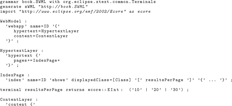
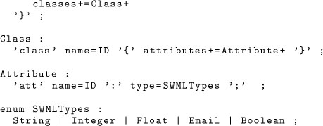
When we compare the resulting grammar with the sWML metamodel shown in Figure 7.5, we see that the assignments for defining the name attributes of the modeling concepts are defined as IDs and not as Strings. This is important for allowing cross references in the textual specifications. For instance, such a cross reference is needed for the type rule IndexPage which defines a cross reference to Class (cf. displayedClass=[Class]). This assignment defines that after the keyword “shows,” a value has to be defined which is equivalent to the name of a class. All other assignments representing references are defined as containment references, e.g., cf. (hypertext=Hypertext). Furthermore, also one terminal rule is defined for the values used for configuring the maximum number of results shown per page. This means, after the reference to the shown class, the number of instances visualized per page is given in square brackets. Please note that this feature may also be modeled as a normal Integer attribute in combination with an additional OCL constraint for restricting the values to fit either 10, 20, or 30. The assignments representing attributes and cross references are defined as single-valued assignments (no additional operator for multiplicity is used), whereas the assignments representing containment references are all defined to be multi-valued (+ operator is used in addition to the = operator).
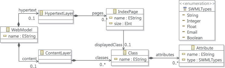
Figure 7.14: Automatically derived metamodel from the Xtext grammar.
In Figure 7.14, the automatically derived metamodel for the Xtext grammar of Listing 7.1 is shown. Please note that the lower multiplicities of all features are automatically set to zero. Further, in the automatic derivation process, the ID attributes of the Xtext grammar are translated to String attributes in the metamodel which corresponds to the manually developed sWML metamodel. Finally, the terminal rules are not explicitly represented in the derived metamodel.
1 In programming languages, EBNF-based grammars [30] are used for this purpose.
2 For instance, the English grammar defines all valid English sentences; the Java grammar defines all valid Java programs.
3 Please note that graphical languages often comprise textual elements, e.g., in UML state machines the names of the states are rendered as text. Furthermore, there are also hybrid approaches for rendering the abstract syntax using textual elements such as supported by MPS http://www.jetbrains.com/mps
6 http://www.eclipse.org/modeling/emft/?project=ecoretools
8 http://wiki.eclipse.org/Emfatic
9 http://www.eclipse.org/modeling/mdt/?project=ocl
10 http://wiki.eclipse.org/MDT/OCLinEcore
12 http://www.eclipse.org/epsilon/doc/evl/
13 http://www.eclipse.org/modeling/m2t/?project=xpand
15 Mappings may be conditional, meaning that the selection of the element used for visualization depends on some feature values of the model elements.
17 The tool palette is the area of a modeling tool offering icons for populating the modeling canvas by dropping elements into it.
18 http://www.eclipse.org/gmt/epsilon/doc/eugenia
19 http://www.eclipse.org/graphiti/
21 For the sake of simplicity, we do not discuss the complete GCS specification for pages such as icons, etc.
22 http://www.eclipse.org/epsilon/doc/hutn/
23 http://www.eclipse.org/gmt/tcs
25 http://www.eclipse.org/Xtext
26 Xtext has been extended to allow also for a metamodel first development approach by generating a default TCS from a metamodel.