10 IDENTIFY ARCHITECTURE STRATEGY
Key Points in This Chapter
• We should invest a minimal, yet sufficient, amount of time to consider our architectural strategy.
• We should keep architectural exploration as lightweight and minimal as possible.
• There are many ways to explore architecture opportunities such as modeling, mobbing, and spikes.
• There are various types of architectural models relevant to our context in the areas of technology, business, and user interface (UI).
• Look for opportunities to increase quality and accelerate delivery by leveraging proven architectural assets.
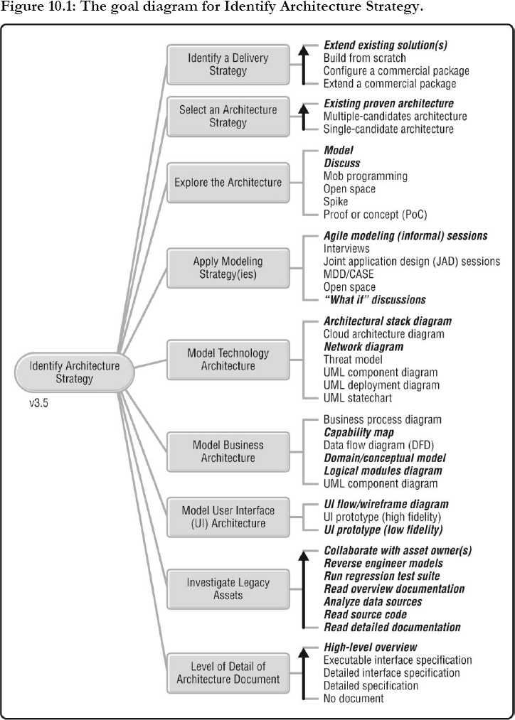
The Identify Architecture Strategy process goal, formerly known as Identify Initial Technical Strategy, is shown in Figure 10.1. This process goal provides options for how we will identify a potential architecture strategy, or sometimes strategies, for producing a solution for our stakeholders. There are several reasons why this is important:
1. It enables effective evolutionary architecture. We can avoid major problems later on in Construction by doing a bit of thinking up front to get going in the right direction while allowing the details to evolve later.
2. We want to identify, and hopefully eliminate, key architectural risks early. A little bit of up-front modeling goes a long way toward identifying critical technical risks early on. We can then mitigate them later through strategies such as proving the architecture with working code early in Construction or via spikes.
3. Avoid technical debt. By thinking through critical technical issues before we implement the solution, we have the opportunity to avoid a technical strategy that needs to be reworked at a future date. The most effective way to deal with technical debt is to avoid it in the first place.
4. Improved DevOps integration. Because DAD teams are enterprise aware, they understand the importance of the overall system life cycle, which includes both development and operations activities. During architecture envisioning, DAD teams will work closely with operations staff to ensure that their solution addresses their needs. This potentially includes mundane issues such as the backup and restore of data and version control of delivered assets, as well as more complex issues such as monitoring instrumentation, feature toggles, and support for A/B testing. DAD teams strive to address DevOps issues throughout the entire life cycle, starting with initial envisioning efforts.
5. Enables us to answer key stakeholder questions. Our teams are being governed, like it or not. It's very likely that at some point our stakeholders will want to know how we believe we will build the solution before they will fund the team. Furthermore, our architectural strategy is an important input into answering similar questions around how much money we need and how long we think this will take.
6. Enhance initial scoping and planning efforts. Our solution architecture will inform our scoping efforts, motivating questions about requirements as well as suggestions for better options. Similarly, architecture also affects our plan in that some architecture strategies take longer to implement than others, architectural activities such as proof-of-concept (PoC) efforts may need to be scheduled, and the cost of new architectural assets may need to be taken into account.
To successfully address this goal, we need to consider several important questions:
• What is our overall strategy for producing a solution? Will we buy, extend, or build new?
• How many architectural strategies should we consider?
• What level of detail do we need to go to?
• What will our approach to exploring the architecture be?
• What models, or views, should we produce (if any)?
• How will we go about understanding the legacy assets that we'll work with?
Identify a Delivery Strategy
Not all IT solutions require building everything new from scratch. In fact, the majority of teams extend existing solutions to provide improved value to their stakeholders. As you can see in the table below, we have several options to choose from.
| Options (Ordered) | Trade-Offs |
| Extend existing solution(s). If we have an existing solution, or existing legacy assets that can be integrated together, we may choose to extend or customize them. | • Typically requires very little architectural modeling.
• We may have a team in place that already understands the existing solution and can efficiently extend it.
• The existing technology may be stale and may have accrued technical debt. |
| Build from scratch. Some solutions are “bespoke,” built new to address the needs of stakeholders. | • Often requires significant investment in exploration of the architecture (via modeling, mob programming, etc.) due to the potential architectural risks involved.
• Allows maximum tailoring of the solution for the stakeholders.
• Due to the uncertainty of the technology and perceived needs, this may be our most risky option. |
| Configure a commercial package. Configure a new or existing package such as SAP or Oracle PeopleSoft to meet stakeholder needs. | • Potentially our least risky option since configuration does not require changing the software and potentially injecting defects.
• Packages often offer greater sophistication than we require and a greater range of functionality than we require, while missing some functionality and being inflexible in portions of their implementation.
• Suitable when we don't have in-house developers who can build or extend a package. |
| Extend a commercial package. Some customization of a commercial package may require extending or modifying the source code of the package. | • Enables us to take advantage of a sophisticated package while tailoring it to our needs.
• Often requires investment in spikes (see below) or a proof of concept (PoC) to explore how the package works in our environment.
• May be difficult to remain on the package's release path when extensive modifications have been made.
• May require redoing some changes when new versions are released.
• May be more cost effective than building from scratch, particularly when a small number of changes are required. |
Select an Architecture Strategy
Our overall architectural strategy is an important deciding factor in how much effort we need to put into initial architecture modeling. When we are extending an existing solution there is very likely little architecture exploration required—the architecture is already known. However, a new solution, particularly one in a complex space, is likely to require a bit of up-front thinking before we dive into Construction. As you can see in the following table, we have several options available to us.
| Options (Ordered) | Trade-Offs |
| Existing proven architecture. This is the most common approach, with roughly 80 % of agile teams being in this situation. | • Modeling will be required when there is the intent to make architecturally significant changes to the current approach.
• People unfamiliar with the existing architecture will need to be given help to learn about it (often a discussion led by our architecture owner). |
| Multiple candidate architectures. Several architectural strategies are identified and worked through, ideally leading to the selection of the most likely architectural strategy. This is a form of set-based design. | • Enables us to have several delivery teams work on the problem, often leading to a “bake-off” where the best strategy to move forward with is chosen.
• Provides us with a “plan B,” a “plan C,” and so on, that we can shift to when our architectural strategy is disproved early in Construction.
• Increases the cost and expense of initial architecture modeling, but potentially reduces long-term risk through considering a wide range of options. |
| Single candidate architecture. Although the team will discuss a range of options, they focus their efforts on a single approach that they feel is best. | • The most common option, particularly for teams that have a limited budget, when architectural modeling is required.
• Focusing on a single strategy is less expensive in the short term, but risks cutting options off early and requiring future rework.
• Can be hard to get agreement around a single vision, requiring leadership from the architecture owner to guide the team through difficult discussions. |
Explore the Architecture
There are several options available to us for how we may decide to explore our architectural strategy. This exploration effort will be led by our architecture owner. The architecture owner on our team should work closely with our organization's enterprise architects, if our organization has any, to understand the architectural direction of our organization so as to guide how we explore the architecture. In fact, our architecture owner might also be an enterprise architect. Several architecture exploration strategies are compared in the following table.
| Options (Not Ordered) | Trade-Offs |
| Model. One or more people discuss and capture an abstraction of what someone would like produced (requirements/needs) or how the team will produce it (architecture/design). A model, or portion thereof, may be captured as a sketch on a paper or a whiteboard, as a drawing in a digital tool, or as text on sticky notes, index cards, paper, or even a digital tool. | • Enables people to work through problem or solution domain issues, thereby reducing risk.
• Face-to-face discussion around a shared sketching environment is known to be the most effective way for people to communicate [Communication].
• Often perceived by developers as something we need sophisticated, digital tooling for (whereas most modeling is done on paper and whiteboards in practice).
• Potential for traditionalists to take modeling too far, to do too much of it too early, because that is what they are familiar with. |
| Discuss. Two or more people gather, either physically or virtually, to talk with one another about an issue. | • Enables people to work through problem or solution domain issues, thereby reducing risk.
• Face-to-face discussion is a very effective way for people to communicate.
• Discussions can go in circles. When this happens, consider shifting to modeling to help achieve focus.
• To persist the conversation we will need to record it, take notes, or model somehow. |
| Mob programming. The team gathers around a single workstation, with one team member coding while the others observe, discuss, and provide advice. The programmer is swapped out regularly and everyone codes at some point. The code is often projected onto a large screen [W]. | • Enables teams to work through a complex technical issue.
• Enables teams to develop an example of how to implement an important, and often reusable, technical strategy.
• Arguably, a face-to-face discussion around a shared sketching environment, where the “sketch” is the source code being projected on the screen.
• Often misunderstood by management and seen as wasteful, as it is perceived as a technique for “many people programming” instead of “many people thinking.” This is due in most part to the name of the technique. |
| Open space. An open space is a facilitated meeting or multiday conference where participants focus on a specific task or purpose (such as sharing experiences about applying agile strategies within an organization). Open spaces are participant driven, with the agenda being created at the time by the people attending the event. Also known as open space technology (OST) or an “unconference” [W]. | • Works well with a disparate group of people that need to hear each other.
• Often produces important insights that leadership may not have been aware of and innovative ideas.
• Requires some up-front planning, facilitation, and follow-through to share the results.
• Some people will not like what appears to be the “unplanned” nature of open space. |
| Spike. Code is written to explore a technology, or combination of technologies, that is new to the team. Spikes typically take a few hours or a day or two. In effect, an informal and small proof of concept (PoC) [ExtremeProgramming]. | • Enables teams to quickly and cheaply learn about how a technology works (or doesn't) in their environment.
• Reduces technical risk by (dis)proving parts of our architectural strategy.
• The code is often of low quality, on purpose, and thrown away afterward. |
| Proof of concept (PoC). A technical prototype that is developed over several days to several weeks to explore a technology. Formal success criteria for the PoC should be developed before it begins. | • Reduces risk by exploring how a major technical feature, often an expensive software package or platform, works in practice within our environment.
• PoCs can be large, expensive efforts that are sometimes run as a mini project.
• Success criteria is often politically motivated and sometimes even oriented toward a predetermined answer. |
Apply Modeling Strategy(ies)
Similar to the Explore Scope goal, we will want to decide how to explore the potential architectural approach(es) for our solution. There are several options available to us for approaching the modeling or exploration of our architecture strategy.
| Options (Not Ordered) | Trade-Offs |
| Agile modeling (informal) sessions. Modeling/planning performed face to face using inclusive tools such as whiteboards and paper [AgileModeling]. | • Works very well with groups of up to seven or eight people, but can be scaled to much larger groups with skilled facilitation.
• Potential for very collaborative and active modeling with stakeholders.
• Requires some facilitation to ensure that a range of issues are addressed.
• Can require significant lead time to schedule.
• Experienced architects, including enterprise architects who our team relies on, may not be comfortable with informal modeling. |
| Interviews. Someone interviews stakeholders individually or in small groups to identify their technical requirements and guidance. | • Expensive way to derive our strategies because it often requires a lot of going back and forth between the people involved.
• Risk missing someone in important discussions, or at least requires additional interviews with the appropriate people involved.
• An option when people are geographically distributed or when people are unwilling to collaborate with a wider group. |
| Joint application design (JAD) sessions. Formal modeling sessions, led by a skilled facilitator, with defined rules for how people will interact with one another [W]. | • Scales to dozens of people.
• Many people may get their opinions known during the session, enabling a wide range of people to be heard.
• Works well in regulatory environments.
• Works well in contentious situations where extra effort is required to keep the conversation civil or to avoid someone dominating the conversation.
• “Architecture by consensus” often results in a mediocre technical vision.
• Formal modeling sessions risk devolving into being specification-focused, instead of communication-focused, efforts. |
| Model-driven development (MDD)/computer-aided software engineering (CASE). Detailed requirements, architecture, and design are captured using complex, software-based modeling tools [W]. | • Works very well for complex solutions being developed in a narrow technical domain, in particular systems engineering.
• Requires significant skill and sophisticated tools on a long-term, ongoing basis to accomplish.
• Many of the modeling tools do not have a comprehensive testing solution available. |
| “What-if” discussions. Identify potential technical and business changes that could impact our architecture. | • Enables us to think through potential situations, and thereby steer our architecture in a better direction.
• Supports a lean “think before we act” approach.
• Potentially motivates teams, particularly those new to agile, to overbuild their solution. |
Model Technology Architecture
As you can see in the following table, there are many potential model types available to explore and capture the technology aspects of our architecture. Our strategy for the technology aspects of our architecture should reflect our organization's technology roadmap (see Align with Enterprise Direction in Chapter 8). We will likely want to do some minimal modeling of the technical architecture for new solutions when:
• Material changes to the architecture of an existing solution are needed.
• Significant integration is required between existing legacy assets.
• A package often requires significant integration with existing legacy assets.
| Options (Not Ordered) | Trade-Offs |
| Architectural stack diagram. Describe a high-level, layered view of the hardware or software (or both) of our solution [ObjectPrimer]. | • Explores fundamental issues around architecture.
• Best suited for layered architectures.
• Well understood by most IT and systems professionals.
• Not well suited to describe architectures based on a network of components or services. |
| Cloud architecture diagram. A style of deployment diagram used to explore how a solution is deployed across on-premises infrastructure and cloud-based infrastructure; typically a freeform diagram. | • Critical for any team where a portion of the “back end” for their solution is deployed to the cloud.
• Easier to understand than UML deployment diagrams.
• Should be combined with threat boundaries (see threat model below) so as to address security concerns.
• This is an emerging architectural view, so most of the advice around this technique is vendor focused at present.
• Can be overly simplistic, particularly when “the cloud” is treated as a nebulous black box. |
| Network diagram. Model the layout of major hardware elements and their interconnections (network topology) [W, ObjectPrimer]. | • Well understood by most IT and systems professionals.
• Can become very large and unwieldy. |
| Threat model. Consider security threats via a form of deployment/network diagram [W]. | • Straightforward way to explore security threats to our solution long before we build/buy it.
• Threat boundaries can be indicated on any type of diagram, although a specific diagram is often useful.
• Can mask a lack of security expertise within the team by making it appear that we've considered the issues. |
| UML component diagram. Describe software components or subsystems, and their interrelationships (software topology) [W, ObjectPrimer]. | • Can be used to explore either technical or business architecture issues.
• Can easily become overly complex. |
| UML deployment diagram. Explore how the major hardware components work together and map major software components to them (solution topology) [W, ObjectPrimer]. | • Well understood by most IT and systems professionals.
• Diagrams can become quite large in complex environments. |
| UML state chart. Explore the dynamic nature of our architecture. Also known as a state machine diagram [W, ObjectPrimer]. | • Particularly useful in real-time systems to explore or even simulate potential behaviors of interacting systems.
• Usually used at the detailed-design level for smaller components. |
Model Business Architecture
In Disciplined Agile, we remind people that we are delivering solutions, not just software. In many situations, the solution being delivered supports new or changed business processes. Our strategy for the business aspects of our architecture should reflect our organization's business roadmap (see Align with Enterprise Direction in Chapter 8). Our team's product owner will be a primary stakeholder of the business architecture and should be actively involved in its exploration. The following table provides a range of potential model types to explore and capture our business architecture.
| Options (Not Ordered) | Trade-Offs |
| Business process diagram. Identify business processes, data sources, and the data flow between them. Common notation options include Business Process Modeling Notation (BPMN) and UML activity diagrams [W]. | • Effective way to visually explore existing or potential processes supported by the solution.
• When sketched collaboratively, process diagrams can be an effective way to communicate with business stakeholders.
• Complex BPMN can motivate overmodeling. |
| Capability map. Depicts what a business does to reach its strategic objectives (its capabilities) rather than how it does it (its processes). Sometimes called a business capability map [CapabilityMap]. | • Captures a stable and long-lasting view of the enterprise that can be used to guide prioritization decisions.
• Easily understood by both business and technical people.
• Can be used to explore both future capabilities as well as existing capabilities.
• At the solution level, connects solution capabilities to implementation.
• At the enterprise level, connects business strategy to execution. |
| Data flow diagram (DFD). Explores the data flows between major processes, subsystems, and the people and organizations that interact with the solution [W, ObjectPrimer]. | • Effective way to explore the high-level processing that the solution is involved with.
• When the notation is kept simple, this tends to be a very intuitive technique to use with stakeholders. |
| Domain/conceptual model. Identifies major business entities and their relationships. Typically captured using data models, entity relationship diagrams (ERDs), or unified modeling language (UML) class diagrams [W, ObjectPrimer]. | • Promotes a common understanding of domain terminology, which helps us to simplify our other artifacts through consistent terminology.
• Provides a high-level start at our data schema and business class schema.
• Supports a domain-driven design (DDD) approach to development [DDD].
• Can motivate overmodeling by people with a traditional data background. |
| Logical modules diagram. Depicts the critical modules (systems, data sources, microservices, frameworks, etc.) or our architecture at a functional level. Sometimes called a logical architecture diagram [W, ObjectPrimer]. | • Promotes a common, high-level understanding of the architecture.
• Useful for thinking through important aspects of the architecture without making implementation decisions about it.
• Can often become too abstract to anyone beyond the people who created it. |
| UML component diagram. Describes software components or subsystems, and their interrelationships (software topology) [W, ObjectPrimer]. | • Can be used to explore either technical or business architecture issues.
• Can easily become overly complex. |
Model User Interface (UI) Architecture
The user interface (UI) is the system to most end users. The UI architecture drives the usability, and hence consumability, of our solution—so it behooves us to invest a bit of time thinking it through up front. The following table provides several common options for exploring and capturing the UI aspects of our architecture. Although these options are also applicable to the Explore Scope process goal described earlier, in this case, our focus is on the architectural applications of these techniques.
| Options (Not Ordered) | Trade-Offs |
| UI flow/wireframe diagram. Depicts the flow between major UI elements (such as pages/screens and reports) [W, ObjectPrimer]. | • Explores a high-level view of how major UI elements will fit together to support one or more usage scenarios, enabling us to explore potential consumability issues long before the UI is built.
• On its own, this technique can be too abstract for stakeholders, so it needs to be supported via prototyping. |
| UI prototype (high fidelity). A mockup of one or more major UI elements using software to explore the detailed screen design [W, ObjectPrimer]. | • Concrete way to quickly explore what people want our solution to do and thereby identify a more consumable solution early in the life cycle.
• When used to design a few key pages/screens, this is an effective way to explore UI design details with stakeholders.
• When used to design all or most of the pages/screens, this leads to a lengthy “big design up front” (BDUF) strategy that often produces a detailed design that proves to be brittle in practice.
• UI designers often fall into the trap of showing stakeholders a beautiful prototype that can't actually be built, thereby setting unreasonable expectations.
• Prototyping tools may not exist for our platform, requiring potentially slower coding.
• Some users believe that the system is “almost done” when they see high-fidelity screen prototypes. |
| UI prototype (low fidelity). A user-centered design technique where we use paper and sketches to mock out the requirements for, or design of, major UI elements. For example, requirements for a report could be identified by manipulating sticky notes on a whiteboard [W, ObjectPrimer]. | • A quick and easy approach that avoids the problems associated with high-fidelity prototypes.
• Can be too abstract for some stakeholders, so we often find we still need to develop high-fidelity prototypes of a few pages/screens to show stakeholders that we understand how they want the UI to be built. |
Investigate Legacy Assets
The majority of agile delivery teams work with one or more legacy assets, be they web services, legacy data sources, or legacy systems. Many times agile teams are responsible for extending and paying down the technical debt within those assets. Unfortunately, in some cases, our team is not familiar with the legacy assets and therefore must learn about them. The following table compares common strategies for investigating legacy assets.
| Options (Not Ordered) | Trade-Offs |
| Collaborate with asset owner(s). The team works with the people who know the legacy assets best to understand the implications of working with them. | • Very effective way to learn about how the asset is actually built and what challenges we're likely to run into working with it.
• Assets owners, or at least people knowledgeable about the asset, often aren't available. |
| Reverse engineer models. Modeling tools are used to visually explore the architecture and design of the asset based on the existing code and data schema. | • Can be a great way to learn about an asset and the dependencies it is involved with.
• These tools often aren't available for all of the technologies used to build the asset or if they are, they are often expensive.
• The models generated can often be overly detailed (a reflection of the architectural problem we face working with it). |
| Run regression test suite. The team works with the regression test suite for the asset to understand the impact of potential changes. | • Automated regression tests are effectively executable specifications that are in sync with the implementation, meaning we can trust them.
• Regression tests work well for people who can understand and work with code.
• Regression test suites rarely exist, or when they do, they're often not sufficient for legacy assets. |
| Read overview documentation. The team reads the available high-level documentation, or the overview portions of detailed documentation, to understand the asset. | • Overview documentation provides a high-level description, including key diagrams, that can be quickly read by team members.
• Likely to be reasonably accurate because of its high-level nature, so can be trusted.
• Enables team members to make reasonable guesses as to where to dive into the implementation to make changes.
• We still need some way to understand the details. |
| Analyze data sources. The team uses data visualization and query tools to explore what is actually stored in a data source. Also called data archaeology. | • Effective way to discover what data are actually being stored within a data source.
• Can be very time-consuming, particularly for a large data source. |
| Read source code. The team works with the source code for the legacy asset to understand how it is built, also called code archaeology. | • Some legacy source code can be difficult to work with, particularly code that has been worked on by many people over the years.
• There may be significant reluctance to change the source code due to high coupling within it and a lack of automated regression tests to identify potential problems when we do.
• We may not have the actual code used to build the currently running version of the asset. |
| Read detailed documentation. The team works with the detailed documentation associated with the asset to understand how it's built. | • Can be a good starting point to understand a legacy asset, in particular the high-level overview portions of the documentation.
• The detailed portions of it are likely out of sync with the implementation so shouldn't be trusted. |
Level of Detail of Architecture Document
Similar to other goals like Explore Scope, we will need to decide what level of detail is appropriate for describing our initial architecture strategy.
| Options (Ordered) | Trade-Offs |
| High-level overview. Capture our architecture strategy with a few key diagrams and concise supporting documentation [AgileModeling]. | • Increases the chance that the architecture model will be used and evolved over time.
• Enables team to coalesce around a technical vision.
• Enables flexibility, particularly when architectural options are left open.
• Detailed design decisions can be deferred to when they can be most appropriately made, consistent with the lean “defer commitment” practice.
• Requires team members to have greater design and architecture skills.
• Team members making deferred decisions must be aware of enterprise architectural direction and guidelines.
• Can motivate overbuilding our solution early in the life cycle, particularly when the team is new to agile.
• May not be sufficient in regulatory situations. |
| Executable interface specification. Capture the interface definitions of critical architectural components (such as microservices, services, or frameworks) using automated tests [APIFirst]. | • Enables teams to safely work on architectural components in parallel.
• Executable specifications are more likely to remain in sync with the application; and when run as part of our automated testing strategy, they reduce the feedback cycle when changes to the interface do occur.
• Requires time to develop and test the executable specifications and mocks/stubs for the architectural components.
• Potentially increases the chance that we will overbuild our solution, which increases both cost and delivery time.
• In regulatory situations, it requires auditors who understand this approach. |
| Detailed interface specification. Capture the interface definitions of critical architectural components using detailed documentation [APIFirst]. | • Enables teams to work on architectural components in parallel.
• Enables us to mock or stub out the interfaces to components early.
• The interface will still need to evolve throughout the project, although hopefully not much, requiring negotiation between the owning subteam and customers of the evolving component.
• Requires time to develop and write the documentation.
• Potentially increases the chance that we will overbuild our solution, which increases both cost and delivery time. |
| Detailed specification. Define, in detail, exactly how we intend to build the solution before we actually do so. This typically includes detailed interface specifications, internal designs, and specifications of cross-cutting concerns. Sometimes referred to as “big design up front” (BDUF). | • Enables teams to work on architectural components in parallel.
• Details can deceive people into believing that the architecture will actually work (when it still hasn't been proven), thereby increasing risk.
• Important decisions are made early in the life cycle based on information that is likely to evolve, thereby increasing risk.
• Decreases morale of developers by taking away the challenges associated around architectural work.
• Increases overhead to evolve the architecture when the requirements change or the chosen technologies evolve.
• Supports a documentation-based governance strategy, increasing organizational risk.
• Requires significant time (and cost) to perform.
• Potentially increases the chance that we will overbuild our solution, which increases cost, delivery time, and overall risk. |
| No document. Don't capture our up-front architectural thinking at all. | • Works well for very simple solutions produced by very small teams.
• Shortens the Inception effort.
• Team members don't have a common architectural vision to work toward, resulting in confusion and wasted effort.
• Too many decisions are deferred to Construction, increasing the chance of rework. |