
Photography by Jérôme Demers
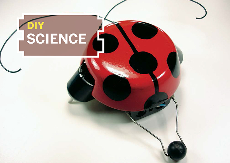
BEETLEBOT
Ultra-simple bugbot navigates obstacles with feelers and switches.

The Beetlebot is a very simple little robot that avoids obstacles on the floor without using any silicon chip — not even an op-amp, and certainly nothing programmable. Two motors propel the bugbot forward, and when one of its feelers hits an obstacle, the bot reverses its opposite motor to rotate around and avoid it. The project uses only 2 switches, 2 motors, and 1 battery holder, and it costs less than $10 in materials (or free, with some scrounging).
Beetlebot in 10 Easy Steps
1. Cut pieces of heat-shrink tubing and use a heat gun or other high-heat source to shrink them onto the motor shafts. Trim the tubing evenly, with a little bit running past the ends of the shafts. These will act as tires, improving traction (Figure B).
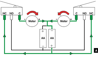
Fig. A: Diagram of Beetlebot running free, not bumped into anything; both motors draw current from the right battery only.
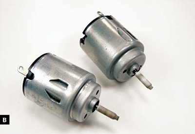
Fig. B: Heat-shrink tubing acts as tires, giving traction to the motor shafts.
2. Glue the SPDT switches to the back of the battery holder, at the end with the wires. The switches should angle out at the 2 corners with their levers angled in toward each other, as shown in Figure C. Also, the contacts farthest from the buttons on each (the normally closed contacts) should touch. This will be the front end of our bugbot.
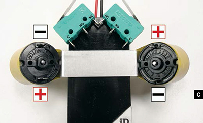
Fig. C: Switches and motor plate glued to the back of the battery holder.
3. Cut the metal strip, mark enough length at each end to hold a motor, and bend each end in at about a 45° angle. This is your motor plate.
4. Examine or test your motors to determine their polarity. Tape the motors onto opposite ends of the motor plate so that their shafts point down and angle out. Orient their positive and negative contacts so that they’ll spin in opposite directions.
MATERIALS
1.5V motors (2) You can often scavenge these from toys, dollar store fans, etc.
SPDT (single pole double throw) momentary switches with metal tabs (2) You can scrounge these from an old VCR or mouse, or buy new ones for $1–$4 apiece.
Electrical wire around 22 gauge
AA batteries (2) You can also use AAAs.
AA battery holder
Spherical bead plastic or wood
Heat-shrink tubing to shrink to the widths of the motor shafts and the antennae connectors
Black electrical tape
Terminal connectors, spade type, small (2)
1"×3" piece of scrap metal plate I used aluminum.
Paper clips (4)
Cyanoacrylate (Super/Krazy) glue or epoxy
Soldering iron and solder
Toggle switch (optional) for on/off switch
FOR THE SHELL (OPTIONAL)
Round plastic lid I used a lid from a container of hair gel, but you can also use a peanut butter jar lid or anything similar.
Auto body filler putty or epoxy glue
Black and red enamel paint and primer
Clear varnish
Small, thin magnets (2) to attach shell to body
5. Use cyanoacrylate glue or epoxy to glue the motor plate down onto the back of the battery holder, just behind the switches (Figure C). Orient the motors so that the left motor spins counterclockwise as you view it from below, and the right one spins clockwise. For aesthetics, I then covered the plate with black electrical tape.
6. Unbend a paper clip, slip it through the bead, and bend it symmetrically on either side to make a caster (Figure D). Attach each end of the clip to the corners of the battery holder at the back. I used hot glue — not very professional. You could also try bending the clip ends under and soldering them to the battery connection tabs, but if you apply too much heat to the tabs, you might melt the plastic and ruin your battery holder. Beware!
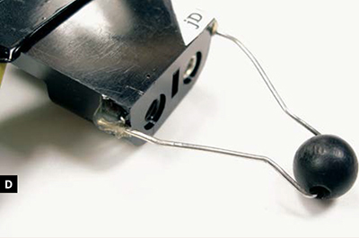
Fig. D: Bent paper clip threaded through a bead and glued to the rear end of the battery holder to make a rolling caster.
Next we’ll wire up the circuit, but first, an explanation: the key is that the 2 batteries work separately. Battery holders usually connect cells in series and combine their voltages, but with the Beetlebot, a wire soldered between the 2 puts them into separate subcircuits. The motors draw from only 1 battery at a time. Each switch’s common connection (C) runs to a motor. The switches’ normally open (NO) terminals connect together and run to the battery holder’s negative lead, while the switches’ normally closed (NC) legs run to the positive lead.
When the bot isn’t hitting anything, voltage from the positive-side battery splits and runs through both motors via the NC terminals, and the negative-side battery is not used at all. But when a switch button is activated, it closes the circuit with the negative-side battery, through the NO terminal. This reverses the motor direction on that side while the unactivated side continues running forward, which results in a quick turn away from the obstacle.
When both switches activate, both motors momentarily run backward, and the bot backs away. (The feelers cross in front, so a bump on one side activates the button on the opposite side.) That’s all there is to it. Now, back to the build.
7. Solder together the 2 switches’ NC terminals that are close or touching. Then solder together their NO terminals, the middle legs. I use pieces of paper clip for short joins like this, since it’s faster and stronger. Then connect the common leg of each switch to the front terminal of its nearest motor (Figure E, top).

Fig. E: Use pieces of paper clip and insulated wire to solder connections between the switches, motors, and battery holder.
8. Solder a wire between 2 motors’ rear terminals. Connect another wire from either one to any contact point on the battery holder that’s electrically in between the 2 batteries (Figure E, bottom). This is the Beetlebot’s all-important “third connection.”
9. Finish the wiring by soldering the battery holder’s positive lead to the switches’ NC terminals, and its negative lead to either of the switches’ NO terminals (Figure F).
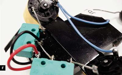
Fig. F: Complete wiring, with battery holder leads soldered to switch terminals.
10. Remove the insulation from the 2 spade connectors, and unbend 2 paper clips. Slip the connectors over the paper clips, then squeeze them down with pliers and solder in place. Dress up the connection with some wide heat-shrink tubing (Figure G). These are the Beetlebot’s feelers. The spade connectors clip onto the switch levers, which makes them easy to detach for packing, and prevents damage to the fragile SPDT switches. The long paper clips give sufficient leverage to activate the switches, even if they seem hard to trigger with your finger directly.
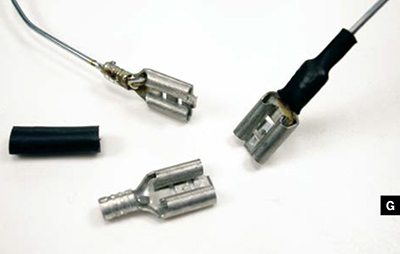
Fig. G: Removable antennae made from paper clips use spade connectors to slip onto switch levers.
Your robot is finished (Figure H)! Add 2 batteries, and it should come to life. If it spins in a tight circle or runs backward, you need to reverse one or both of the motor connections. To change the bot’s speed or to make it run straighter, bend the metal plate to adjust the motors’ angles.
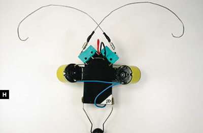
Fig. H: The bare-bones Beetlebot, finished and working, but without any switch or decorative shell.
For additional diagrams of how the circuit works, see makezine.com/projects/beetlebots.
Adding an On/Off Switch (Optional)
Every time you want to stop the robot, you need to remove the battery, which can get annoying. To solve this problem, splice a toggle switch onto the “third connection” wire between the motors and the batteries. Cut the wire, then solder in the switch and glue it to the edge of the battery holder. I neatened this connection up with more heat-shrink (Figure I).
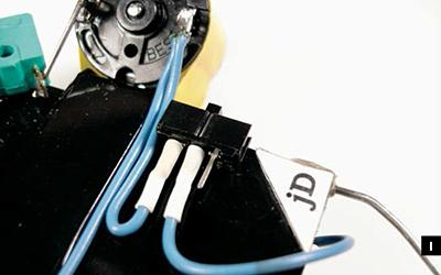
Fig. I: The Beetlebot’s on-off switch connects between the motors and batteries.
Making the Shell (Optional)
Now here’s the aesthetic part: adding the shell. I made mine out of the green plastic lid from a container of hair gel.
1. Fit the lid over the bot and cut holes in the sides to make room for the motors and the front switches/antennae (Figure J).
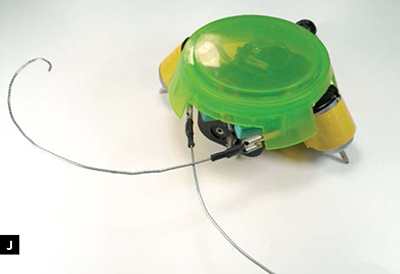
Fig. J: Plastic lid cut to accommodate motors and antennae.
2. To make the shell more round, cover it with auto body putty (watch out — it cures pretty fast!) or epoxy glue, and then use files to shape and smooth it (Figure K). For final touch-up, I filled in any holes with a softer putty.
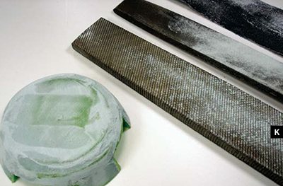
Fig. K: Building up and shaping the shell with auto body putty.
3. After sanding the lid smooth, give it a couple coats of primer, and then paint it. To make a ladybug beetle pattern, I started by painting the whole thing black (I also painted the antennae black). Then I used a dime as a template to cut round pieces of masking tape, which I applied to the lid along with a thin masking tape centerline (Figure L).
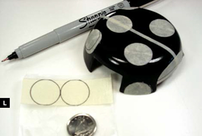
Fig. L: Dime-sized masking tape circles give Beetlebot its spots.
I painted glossy red over everything, and then removed the tape. For the final polish, I sanded the whole thing with very fine sandpaper and some water, which gives a glossier finish than sanding dry; this is a trick I learned from a friend who was restoring a guitar. I let everything dry and gave it 2 coats of clear varnish.
4. To connect the shell to your robot, you can glue it directly to the battery holder, or you can use magnets; glue one inside the lid and another in a matching position on the battery holder. This lets you remove the shell easily, to show your friends the insides of your biomech bug!
Jérôme Demers is a student in electronics engineering at the University of Sherbrooke in Québec. He is currently working on advanced sumo robots in both the 500g and 3kg categories.