Programs such as
addTwoNums call the SER_GetChar() and SER_PutChar() functions to output ASCII characters to a terminal. The Retarget.c file redefines the fgetc() and fputc() functions, which, in turn, call SER_GetChar() and SER_PutChar(). These low-level functions illustrate some important I/O models that we'll explore using a program that checks if a string entered is a palindrome (for example, radar, civic, and level are palindromes). We'll call this recipe palindrome_c3v0.
Follow the steps outlined to configure UART ports:
- Create a project named palindrome; use the RTE manager to configure the board as we did for
addTwoNums_c3v0folder, in the Performing arithemetic operations recipe. - Create a file named
palindrome.cand copy theSystemClock_Config(void)function and associated boilerplate from a previous recipe. Add the following#includestatements:#include "stm32F4xx_hal.h" #include <stdio.h> #include <string.h> #include "Serial.h" #include "cmsis_os.h"
- Add a function named
strRev ()to thepalindrome.cfile:/* * strRev - returns reversed a string *******/ char * strRev(char *str) { int i = strlen(str)-1,j=0; char ch; while(i > j) { ch = str[i]; str[i]= str[j]; str[j] = ch; i--; j++; } return str; } - Add a
main ()function to thepalindrome.cfile and add this file to the project:/* * main *******/ int main (void) { char a[100], b[100]; HAL_Init (); /* Init Hardware Abstraction Layer */ SystemClock_Config (); /* Config Clocks */ SER_Init(); for (;;) { printf("Enter the string to check for palindrome "); scanf("%s", a); strcpy(b,a); strRev(b); if (strcmp(a,b) == 0) printf("Entered string IS a palindrome. "); else printf("Entered string IS NOT a palindrome. "); } } - Remember to add
Retarget.c,Serial.candSerial.hto the project. - Open the project options dialog, click the Target tab, and check Use MicrLIB.
- Build, download, and run the program.
The a array stores the string that is entered. The string is copied to the b array and the strrev() function is called to reverse it. The strcmp() function (defined in the string.h library) is used to check whether the two strings match. The strrev() function copies and reverses the string character by character (remember that strings are terminated with a NULL character).
The SER_PutChar() function declared in Serial.c outputs characters by writing to the USART Data Register (DR), as follows:
/*--------------------------------------------------------------
 *       SER_PutChar:  Write a character to Serial Port
 *--------------------------------------------------------------*/
int32_t SER_PutChar (int32_t ch) {
#ifdef __DBG_ITM
  int i;
  ITM_SendChar (ch & 0xFF);
  for (i = 10000; i; i--);
#else
  while (!(UART4->SR & 0x0080));
  UART4->DR = (ch & 0xFF);
#endif

  return (ch);
}
The UART data register is referenced by a pointer:
UART4->DR;
Note
Please note that the STM32F4xx integrates both Universal Synchronous/Asynchronous Receiver Transmitter (USART) and Universal Asynchronous Receiver Transmitter (UART) hardware. USARTs can be configured to operate both synchronously and asynchronously. We configure a UART that is connected to the 9-pin D-type connector; hence, output is achieved by writing to UART4 rather than USARTx.
Once we have written to the data register, the digital value is output serially, one bit at a time, by the hardware. As this takes considerably longer than it takes to load data in parallel (the exact time taken will depend on the baud rate chosen), we must be careful not to load the DR with a new value until the previous one has been successfully transmitted. The previous line of code is as follows:
while ( !(UART4->SR & 0x0080) )
  /* empty statement */ ;
This line of code achieves this by checking bit 7 of the UART's Status Register (SR). Repeatedly reading the Status Register in a loop is called polling the Status Register (or spinning on the Status Register). A similar situation occurs in SER_GetChar (), but here we poll the Status Register to check whether a character has been received (that is, a bit-7 set), as follows:.
while ( !(UART4->SR & 0x0020) )
  ;
Polling or programmed I/O is the simplest I/O model that we can conceive and the corresponding empty while statements are known as busy-while loops. Programmed I/O operations are performed in the main thread of execution, so the busy-while loops prevent the CPU from doing any useful work. If the program is simple, then this is not too inconvenient, but in most cases, we must look to other more efficient I/O programming models, such as interrupt-driven I/O, and Direct Memory Access.
A flexible device driver really needs to support all three I/O models, that is, programmed I/O, interrupt-driven I/O, and DMA I/O. The USART device driver that is shipped with uVision 5 does exactly this. However, configuring this code is challenging, especially for novice programmers, so for the time being we'll develop our own simple drivers to gain some understanding of the mechanisms before migrating to ARM's library.
Embedded processors use serial ports to communicate with Data Terminal Equipment (DTE) and Data Communications Equipment (DCE) using the RS232 standard. Previous recipes, such as addTwoNums_c3v0, use RS232 to communicate with a PC running PuTTY to emulate a DTE. The RS232 signals are represented by voltage levels with respect to a system common (power / logic ground). The idle state (MARK) has the signal-level negative with respect to common, and the active state (SPACE) has the signal-level positive with respect to common. RS232 transmits data serially, as shown in the following figure:
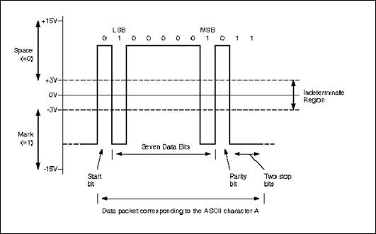
Serial data is transmitted and received in normal USART mode as frames comprising the following:
- An Idle Line prior to transmission or reception
- A start bit
- A data word (7, 8, or 9 bits), the least significant bit first
- 0.5, 1, 1.5, or 2 stop bits, indicating that the frame is complete
The STM400Fxxx USART that is described in STM's Reference manual RM00090 uses a fractional baud rate generator with a 12-bit mantissa and 4-bit fraction. The USART employs the following:
- A status register (USART_SR)
- Data Register (USART_DR)
- A baud rate register (USART_BRR)—12-bit mantissa and 4-bit fraction
- A Guardtime Register (USART_GTPR) in case of Smartcard mode
When data is transmitted asynchronously (without a shared common clock), the receiver and transmitter are synchronized by embedding timing information in the data signal by appending a "start" bit. The seven, eight, or nine data bits are appended after the start bit, a parity bit is added to detect errors, and the packet is terminated by one (or two) stop bits. The transmission rate (time allocated for each bit) is determined by the baud rate.
Configuring the USART involves writing appropriate values to the USART registers #ifdef and #else are preprocessor directives that facilitate conditional compilation):
/*--------------------------------------------------------------
 *       SER_Init:  Initialize Serial Interface
 *--------------------------------------------------------------*/
void SER_Init (void) {
#ifdef __DBG_ITM  ITM_RxBuffer = ITM_RXBUFFER_EMPTY;
#else
  RCC->APB1ENR  |= (1UL << 19);          /* Enable USART4 clock */
  RCC->APB2ENR  |= (1UL <<  0);            /* Enable AFIO clock */
  RCC->AHB1ENR  |= (1UL <<  2);           /* Enable GPIOC clock */

  GPIOC->MODER  &= 0xFF0FFFFF;
  GPIOC->MODER  |= 0x00A00000;
  GPIOC->AFR[1] |= 0x00008800;            /* PC10 UART4_Tx,
                                            PC11 UART4_Rx (AF8) */

  /* Configure UART4: 115200 baud @ 42MHz,
                      8 bits, 1 stop bit, no parity */
  UART4->BRR = (22 << 4) | 12;
  UART4->CR3 = 0x0000;
  UART4->CR2 = 0x0000;
  UART4->CR1 = 0x200C;
#endif
}
Writing to the UART4->BRR baud rate register sets the baud rate. STM's Reference manual RM00090 describes how to configure the Serial Ports. The baud rate is given by  .
.
Where f_clk is the clock frequency of the USART clock, and USART_DIV is a 16-bit unsigned fixed-point number with a 12-bit mantissa and 4-bit fraction. In our case, we need a baud of 115200 and the APB1 domain clock is 48 MHz. Hence, missing f_clk again defined as eqn. object. = 22.78610 = 0000000000010110.11002, so DIV_Mantissa = 2210, and DIV_Fraction = 12/16. Hence, referring to the description of the Baud Rate Register, we have the following:
UART4->BRR = (22 << 4) | 12;
|
31 |
30 |
29 |
28 |
27 |
26 |
25 |
24 |
23 |
22 |
21 |
20 |
19 |
18 |
17 |
16 |
|
Reserved | |||||||||||||||
|
15 |
14 |
13 |
12 |
11 |
10 |
9 |
8 |
7 |
6 |
5 |
4 |
3 |
2 |
1 |
0 |
|
DIV_Mantissa(11:0) |
DIV_Fraction(3:0) | ||||||||||||||
|
rw |
rw |
rw |
rw |
rw |
rw |
rw |
rw |
rw |
rw |
rw |
rw |
rw |
rw |
rw |
rw |
USART Control Register 1 provides some USART control functions:
|
31 |
30 |
29 |
28 |
27 |
26 |
25 |
24 |
23 |
22 |
21 |
20 |
19 |
18 |
17 |
16 |
|
RESERVED | |||||||||||||||
|
15 |
14 |
13 |
12 |
11 |
10 |
9 |
8 |
7 |
6 |
5 |
4 |
3 |
2 |
1 |
0 |
|
OVER8 |
RESER-VED |
UE |
M |
WAKE |
PCE |
PS |
PEIE |
TXEIE |
TCIE |
RXNEIE |
IDLEIE |
TE |
RE |
RWU |
SBK |
|
rw |
res |
rw |
rw |
rw |
rw |
rw |
rw |
rw |
rw |
rw |
rw |
rw |
rw |
rw |
rw |
Bits 2, 3, and 12 are set when 0x200C is written to Control Register 1 (CR1); this enables the USART (bit-12) and also enables the USART transmitter (bit-3) receiver (bit-2) functions. Bits 15, 12, and 9 are clear. This selects oversampling by 16 (bit-15), 8 data bits (bit-12), and even parity (bit-9). Bits 12:13 of CR2 are clear; hence, we have 1 stop-bit. Control register 3 functions are unused.
Other statements in
SER_Init() connect appropriate clocks that are sourced from the Real Time Clock Control (RCC) peripheral and configure the GPIO to provide input and output for the USART by means of the Alternate Function logic. Please note that pins are an expensive microcontroller commodity, so GPIO pins are programmed to connect to a range of peripherals. We discuss GPIO Alternate Function in more detail in Chapter 4, Programming I/O.