
One of the primary selling points of pfSense is that deploying pfSense routers on our network enhances the overall reliability of the network. A single network component, however – for example, a single router or a single web server – still represents a single point of failure. Even in the absence of hardware failure, a single network component may not be adequate in accommodating the level of traffic on our network. For that reason, we need to consider eliminating single points of failure from our network whenever possible. This process is two-pronged, and involves incorporating both redundancy and high availability:
- Redundancy is defined as the duplication of critical components. Redundancy can be both active and passive. With passive redundancy, we incorporate excess capacity into the network, so that when an individual component fails, resources are still available. An example of this would be having two or more redundant web servers. If one server fails, the website should still be available. Active redundancy involves monitoring components and doing an automatic reconfiguration if a component fails. This might involve, for example, having a spare, inactive web server on the network. When the primary web server goes down, the failure is detected and the spare becomes active. As you may have guessed, both forms of redundancy are implemented in pfSense.
- High availability is defined as ensuring a specified level of operational performance over a prolonged period of time. In practice, it means incorporating some of the same elements as redundancy. Single points of failure are eliminated when possible, and we seek to detect failures when they occur and provide for reliable switchover to the redundant components. Again, we can use pfSense to provide high availability.
pfSense incorporates redundancy and high availability through load-balancing and Common Address Redundancy Protocol (CARP). Both of these topics will be covered in this chapter. This chapter will cover the following:
- An example network
- Basic load balancing and CARP concepts
- Configuring load balancing
- CARP configuration
- An example load balancing and CARP configuration
- Troubleshooting
To illustrate load balancing and CARP, we will reintroduce our example network from Chapter 3, Working with VLANs, and Chapter 4, pfSense as a Firewall. As you might recall, our example network had multiple segments; one of these network segments was the DMZ (de-militarized zone), to which we added an FTP server. The FTP server is accessible on the Internet; therefore, we isolated in on a separate segment.
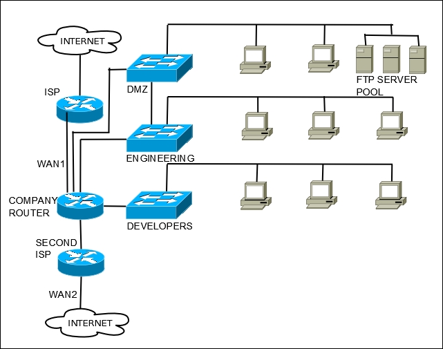
Our example network, with two WAN connections and an FTP server pool.
Let's also assume that we have added a second WAN connection to the example network, in order to ensure Internet availability when one of the ISPs goes down. There are three distinct issues we seek to address through the use of load balancing and CARP on our network:
- We recognize that the pfSense firewall/router that resides at the boundary between the Internet and our local network represents a single point of failure. Therefore, we want to introduce at least one redundant firewall, which will be invoked in the case of failure.
- We want to distribute outbound traffic evenly between our two WAN connections. This will require some form of load balancing.
- We also recognize that the FTP server represents a single point of failure. We want to have at least one additional FTP server, and create a server pool containing all the available physical servers.
We thus have a fairly clear idea of what needs to be done on our example network. As we take a closer look at load balancing and CARP, we will get a clearer idea as to how these elements might be implemented within our network.